

12-2018
Fachzeitschrift für Hochfrequenz- und Mikrowellentechnik
Fachzeitschrift für Hochfrequenz- und Mikrowellentechnik

Erfolgreiche ePaper selbst erstellen
Machen Sie aus Ihren PDF Publikationen ein blätterbares Flipbook mit unserer einzigartigen Google optimierten e-Paper Software.
RF & Wireless<br />
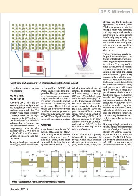
Figure 9: 8 x 16 patch antenna array (<strong>12</strong>8-element) with corporate feed (single-feed port)<br />
corrective action (such as applying<br />
braking).<br />
Multi-Beam/<br />
Multi-Range<br />
A typical ACC stop-and-go<br />
system requires multiple short<br />
and long-range radar sensors<br />
to detect nearby vehicles. The<br />
shorter range radar typically<br />
covers up to 60 m with an angle<br />
coverage up to ±45°, allowing<br />
the detection of the vehicle’s<br />
adjacent lanes that may cut<br />
into the current travel lane. The<br />
longer-range radar provides<br />
coverage up to 250 m and an<br />
angle of ±5° to ±10° to detect<br />
vehicles in the same lane, further<br />
ahead.<br />
To support multiple ranges and<br />
scan angles, module manufacturers<br />
such as Bosch, DENSO, and<br />
Delphi have developed and integrated<br />
multi-range, multi-detection<br />
functionality into increasingly<br />
capable and cost sensitive<br />
sensors using multi-channel<br />
transmitter (TX)/receiver (RX)<br />
architectures. These different<br />
ranges can be addressed with<br />
multi-beam/multi-range radar by<br />
employing radar technology such<br />
as FMCW and digital beamforming<br />
with antenna array design.<br />
Antenna<br />
A multi-modal radar for an ACC<br />
system [2] based on an FMCW<br />
radar driving multiple antenna<br />
arrays is shown in Figure 7.<br />
This multi-beam, multi-range<br />
radar with digital beam forming<br />
operates at both 24 and 77 GHz,<br />
utilizing two switching-array<br />
antennas to enable long range<br />
and narrow-angle coverage<br />
(150 m, ±10°) and short range<br />
and wide-angle coverage (60 m,<br />
±30°). This example illustrates<br />
the use of multiple antennaarray<br />
systems, including multiple<br />
(5 x <strong>12</strong> element) series-fed<br />
patch arrays (SFPAs) for long<br />
range, narrow-angle detection<br />
(77 GHz), a single SFPA (1 x <strong>12</strong><br />
elements designed for 24 GHz)<br />
for short, wide-angle detection,<br />
and four (1 x <strong>12</strong>) SFPAs for the<br />
receiver that were required for<br />
this type of system.<br />
Radar performance is greatly<br />
influenced by the antenna technology,<br />
which must consider<br />
electrical performance such as<br />
gain, beam width, range, and<br />
physical size for the particular<br />
application. The multiple, fixed<br />
TR/RX antenna arrays in the<br />
example radar were optimized<br />
for range, angle, and side-lobe<br />
suppression. A patch antenna<br />
is relatively easy to design and<br />
manufacture and will perform<br />
quite well when configured<br />
into an array, which results in<br />
an increase of overall gain and<br />
directivity.<br />
The performance of a rectangular<br />
patch antenna design is controlled<br />
by the length, width, dielectric<br />
height, and permittivity of<br />
the antenna. The length of the<br />
single patch controls the resonant<br />
frequency, whereas the width<br />
controls the input impedance<br />
and the radiation pattern. By<br />
increasing the width, the impedance<br />
can be reduced. However,<br />
to decrease the input impedance<br />
to 50 Ohms often requires a very<br />
wide patch antenna, which takes<br />
up a lot of valuable space. Larger<br />
widths can also increase the<br />
bandwidth, as does the height of<br />
the substrate. The permittivity of<br />
the substrate controls the fringing<br />
fields with lower values,<br />
resulting in wider fringes and<br />
therefore better radiation. Decreasing<br />
the permittivity also increases<br />
the antenna’s bandwidth.<br />
The efficiency is also increased<br />
with a lower value for the permittivity.<br />
Designing a single patch antenna<br />
or array is made possible through<br />
the use of design software that<br />
utilizes EM analysis to accurately<br />
simulate and optimize performance.<br />
The NI AWR Design<br />
Environment platform includes<br />
AXIEM 3D planar and Analyst<br />
3D finite element method (FEM)<br />
Figure 10: Series feed 1 x 8 patch array with parameterized modifiers<br />
hf-praxis <strong>12</strong>/<strong>2018</strong> 63


