

12-2018
Fachzeitschrift für Hochfrequenz- und Mikrowellentechnik
Fachzeitschrift für Hochfrequenz- und Mikrowellentechnik

Erfolgreiche ePaper selbst erstellen
Machen Sie aus Ihren PDF Publikationen ein blätterbares Flipbook mit unserer einzigartigen Google optimierten e-Paper Software.
RF & Wireless<br />
Testing High Power GaN Amplifiers for Radar<br />
Signals using Peak Power Meters<br />
GaN technology has<br />
become a staple for<br />
high power amplifiers<br />
(PAs) used in radar<br />
applications. Moreover,<br />
the high power and/or<br />
the radar application<br />
often require the signals<br />
to be pulsed.<br />
Measuring and characterizing<br />
pulsed RF signals used in radar<br />
applications present unique challenges.<br />
This article explains why<br />
the peak power meter is a must<br />
have test instrument for characterizing<br />
the behavior of pulsed RF<br />
PAs used in radar systems.<br />
Pulsed radar signals are “on” for<br />
a short time followed by a long<br />
“off” period. During “on” time,<br />
the system transmits anywhere<br />
from kilowatts to megawatts of<br />
power. The high-power pulsing<br />
can stress the power amplifier<br />
(PA) in a number of ways both<br />
during the “on/off” transitions<br />
and during prolonged “on”<br />
periods. As higher demands<br />
are being placed on these PAs<br />
in areas such as output power<br />
level, linearity, and efficiency,<br />
the behavior of the amplifier<br />
needs to be thoroughly tested<br />
and evaluated. The time domain<br />
nature of the pulsed RF signal<br />
necessitates time domain signal<br />
analysis. This article explains<br />
why a peak power meter is the<br />
ideal test instrument for characterizing<br />
the behavior of GaN<br />
power amplifiers used in radar<br />
systems.<br />
GaN Radar Power<br />
Amplifier Technology<br />
Overview<br />
For many years, radar systems<br />
employed vacuum electron<br />
devices (VEDs), commonly<br />
referred to as tubes, for high<br />
power applications. Most commonly<br />
used VED technologies<br />
in radar applications today are<br />
Traveling Wave Tubes (TWT),<br />
Klystrons, Magnetrons and<br />
Gyrotrons.<br />
TWT amplifiers (TWTAs) provide<br />
multi-octave bandwidths,<br />
multi-kilowatt peak power output,<br />
support of high frequencies,<br />
as well as ruggedness. However,<br />
TWTAs are relatively costly,<br />
large vacuum tube structures<br />
that require significant size and<br />
mass. VEDs and their associated<br />
high-voltage power supplies<br />
often suffer from short lifetimes,<br />
varying from as few as several<br />
hundred hours to ten thousand<br />
hours for relatively benign environments.<br />
To address these shortcomings,<br />
engineers have researched<br />
alternatives.<br />
About three decades ago semiconductor-based<br />
PA solutions<br />
called solid state power amplifiers<br />
(SSPA) started making<br />
modest inroads as an alternative<br />
technology for certain radar<br />
applications.<br />
Silicon-based laterally diffused<br />
metal oxide (LDMOS) offered<br />
a few hundred watts of output<br />
power, ruggedness and reliability.<br />
Its upper frequency limit of<br />
about 3 GHz (S-Band) at high<br />
output powers curbed its applicability<br />
in radar. Gallium arsenide<br />
(GaAs), a wide-bandgap<br />
semiconductor, overcame the<br />
high frequency deficiency of<br />
LDMOS, reaching above 100<br />
GHz, yet its lower operating voltage<br />
limits its output power capability.<br />
High power GaAs amplifiers<br />
often require paralleling of<br />
multiple devices to reach desired<br />
power levels at the expense of<br />
loss in efficiency. GaAs found<br />
common use in radar but still was<br />
Author:<br />
Walt Strickler,<br />
VP GM Boonton<br />
Application Note 0918/EN<br />
Wireless Telecom Group<br />
WTGinnovation<br />
www.boonton.com<br />
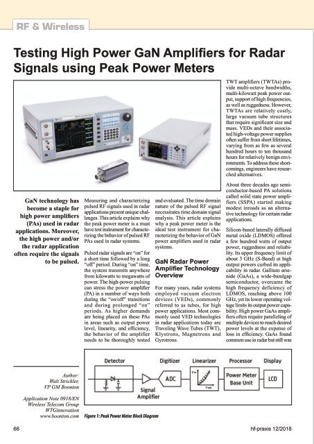
Figure 1: Peak Power Meter Block Diagram<br />
66 hf-praxis <strong>12</strong>/<strong>2018</strong>


