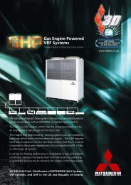
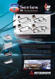
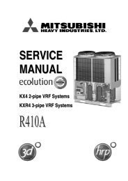
SERVICE MANUAL - Mitsubishi Heavy Industries Ltd.
SERVICE MANUAL - Mitsubishi Heavy Industries Ltd.
SERVICE MANUAL - Mitsubishi Heavy Industries Ltd.

You also want an ePaper? Increase the reach of your titles
YUMPU automatically turns print PDFs into web optimized ePapers that Google loves.
Model: FDUR series<br />
Drain motor<br />
L3<br />
L2<br />
CNJ2 CNR<br />
CNT CNV<br />
52X3<br />
Connector<br />
(CNT)<br />
52X5 52X4<br />
CNO<br />
52X2 52X1 52X6<br />
CNW1 CNM3<br />
Heat exchanger thermistor,<br />
Return air thermistor<br />
(Thl-R1, Thl-A)<br />
PCB power supply connector<br />
(Primary side)<br />
Heat exchanger thermistor<br />
(Thl-R2)<br />
Remote controller<br />
CNH CNN1 CNN2 CNF CNB CNQ<br />
SW2 SW10<br />
F1<br />
CNW0<br />
J1 (SW7-1)<br />
With<br />
None<br />
Input signal - Reverse invalid<br />
Input signal - Rus stop<br />
J2 (SW7-2)<br />
Heating thermostat OFF-Lo<br />
Heating thermostat OFF-Stop, Lo<br />
J3 (SW7-3)<br />
Normal operation operable<br />
Operation permission prohibited<br />
J4 (SW7-4)<br />
Normal<br />
Heating temp. +3<br />
J6 (SW8-2)<br />
Freeze prevention fan control activated<br />
Freeze prevention fan control deactivated<br />
(1)<br />
With<br />
None (1)<br />
With<br />
None (1)<br />
With<br />
None (1)<br />
With<br />
None (1)<br />
● Change by the jumper wire<br />
Name Function<br />
Note (1) “None” means that jumper wire is not provided on the PCB or the<br />
connection is cut<br />
(2) The replacement board is not equipped with jumpers J1 ~ J4, J6.<br />
Instead, SW7 and 8, with the same functions as jumpers J1~J4, J6, are<br />
used in the position where the jumpers were previously. Set SW7 and 8<br />
locally in accordance with the above table.<br />
L1<br />
CNE<br />
CNG<br />
Power supply<br />
CNW2<br />
- 11 -<br />
Address swith<br />
(SW2)<br />
LED2<br />
LED1<br />
DIP switch<br />
(SW5)<br />
J10~J11<br />
(SW10)<br />
L4<br />
SW8 SW9 CNZ CNI<br />
SW5 SW7<br />
CNK1<br />
CNK2<br />
PCB power supply connector<br />
(Secondary side)<br />
DIP switch<br />
(SW9)<br />
J1~J4<br />
(SW7)<br />
F2<br />
J6<br />
(SW8)<br />
F3<br />
CNO<br />
CNA<br />
Float switch<br />
● Control change switch (SW5, SW9, SW10)<br />
Function of DIP switch SW5 (Usually all turned OFF)<br />
Switch Function<br />
SW5-3<br />
ON<br />
OFF<br />
ON Setting time : 1000hrs. (Unit stop)<br />
SW5-4<br />
OFF Setting time : 1000hrs. (Display)<br />
ON Setting time : 600hrs. (Display)<br />
OFF Setting time : 180hrs. (when shipped from factory)<br />
Function of DIP switch SW9 (Usually all turned OFF)<br />
Switch Function<br />
SW9-3<br />
ON<br />
OFF<br />
Emergency operation<br />
Normal<br />
SW9-4<br />
ON<br />
OFF<br />
Fan control : High speed (High Ceiling)<br />
Fan control : Standard<br />
Function of DIP switch SW10 (Usually all turned OFF)<br />
SW10-2<br />
(J10)<br />
Switch Function<br />
OFF<br />
ON<br />
SW10-3<br />
(J11)<br />
OFF<br />
ON<br />
OFF<br />
ON<br />
Remote controller air flow –<br />
Remote controller air flow 1 speed<br />
Remote controller air flow 2 speed<br />
Remote controller air flow 3 speed