SERVICE MANUAL - Mitsubishi Heavy Industries Ltd.
SERVICE MANUAL - Mitsubishi Heavy Industries Ltd.
SERVICE MANUAL - Mitsubishi Heavy Industries Ltd.

You also want an ePaper? Increase the reach of your titles
YUMPU automatically turns print PDFs into web optimized ePapers that Google loves.
<strong>SERVICE</strong><br />
<strong>MANUAL</strong><br />
FDA Series Split Systems<br />
FDA Series Multi Systems
MITSUBISHI HEAVY INDUSTRIES - PAC <strong>SERVICE</strong> <strong>MANUAL</strong><br />
INDEX<br />
MAINTENANCE DATA 2<br />
ERROR CODES 4<br />
PCB INDOOR UNITS 8<br />
ERROR DISPLAY & REMEDY CHART 12<br />
PCB OUTDOOR UNITS 22<br />
ERROR DISPLAY – OUTDOOR UNIT 25<br />
OPERATIONAL DATA CHECK – WIRED CONTROLLER 35<br />
REMOTE CONTROL – WIRED 36<br />
- SETTING FUNCTIONS 37<br />
ERROR DISPLAY – WIRELESS CONTROL 43<br />
REMOTE CONTROL WIRELESS 44
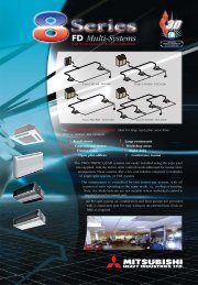
1. MAINTENANCE DATA<br />
1.1 Servicing<br />
(1) Evacuation<br />
The evacuation is a procedure to purge impurities, such as noncondensable gas, air, moisture from the refrigerant equipment by<br />
using a vacuum pump. Since the refrigerant R410A is very insoluble in water, even a small amount of moisture left in the refrigerant<br />
equipment will freeze, causing what is called ice clogging.<br />
Evacuation procedure<br />
Make sure that the both service valves of gas and liquid line are fully opened.<br />
(a) Check to ensure that there is no internal pressure<br />
in the unit. If there is an internal pressure,<br />
it should be relived through the service<br />
port.<br />
(b) Connect the charging hose of the gauge manifold<br />
to the service port of the gas piping.<br />
Close high pressure valve 2 of gange manifold.<br />
Outdoor unit<br />
(c) Connect the charging hose A to a vacuum<br />
pump.<br />
Repeat evacuation in the following sequence.<br />
Vacuuming begins<br />
Please run the<br />
vacuum pump for at<br />
least one hour after<br />
the vacuum gauge<br />
shows -101kPa or<br />
lower. (-755mmHg or<br />
lower)<br />
Vacuuming completed<br />
No increase in the<br />
reading of the<br />
vacuum gauge's<br />
needle pointer.<br />
Notes (1) Do not use the refrigerant pressure to expel air.<br />
Notes (2) Do not use the compressor for evacuation.<br />
Notes (3) Do not operate the compressor in a vacuum condition.<br />
Vacuum gauge check<br />
When the vacuum gauge's needle pointer creeps up,<br />
there is moisture left in the system or a leak. Pull air<br />
again after you have checked the system for a leak and<br />
rectified it. Use a reverse flow stop adapter to prevent<br />
the vacuum pump's lubricant oil from flowing into the<br />
refrigerant system.<br />
- 2 -<br />
Handle Lo<br />
Charge hose<br />
(for R410A only)<br />
Charge valve<br />
Vacuum adapter<br />
(for R410A only)<br />
Gus line<br />
Charge port<br />
Indoor unit<br />
Liquid line<br />
Gauge manifold<br />
(for R410A only)<br />
1 2<br />
Vacuum<br />
pump<br />
Handle Hi<br />
Charge hose A<br />
(for R410A only)<br />
3<br />
Refrigerant<br />
cylinder<br />
Notes (1) Refer to the exterior-view drawing for the position of the service valve.<br />
Notes (2) When connecting of ther service valve, flare connection for both the<br />
indoor and outdoor unit.
(2) Refrigerant charging<br />
(a) After the evacuation shown in the above, change the connection of the charge hose A to the refrigerant cylinder.<br />
(b) Purge air from the charge hose A .<br />
First loosen the connecting portion of the charge hose at the gauge manifold side and open valve 3 for a few seconds, and<br />
then immediately retighten it after observing that gas has blown out from loosened connecting portion.<br />
(c) Open valves 1 and 3 then gas refrigerant begins flowing from the cylinder into the unit.<br />
When refrigerant has been charged into the unit to some extent, refrigerant flow becomes stagnant. When that happens, start<br />
the compressor in cooling cycle until the system is filled with the specified amount of gas, then close valves 1 and 3 and<br />
remove the gauge manifold. Cover the service port with caps and tighten them securely.<br />
(d) Check for gas leakage by applying a gas leak detector around the piping connection.<br />
(e) Start the air conditioner and make sure of its operating condition.<br />
1.2 Trouble shooting for refrigerant circuit<br />
(1) Judgement of operating condition by operation pressure and temperature difference<br />
Making an accurate judgement requires a skill that is acquired only after years of experience, one trouble may lead to an another<br />
trouble from a single trouble source and several other troubles may exist at the same time which comes from a undetected different<br />
trouble source.<br />
Filtering out the trouble sources can be done easier by comparing with daily operating conditions. Some good guides are to judge<br />
the operating pressure and the temperature difference between suction air and delivery air.<br />
Following are some pointers,<br />
Pressure<br />
Indication<br />
low<br />
Circuit Too<br />
A little low<br />
- 3 -<br />
Trouble cause<br />
High side<br />
Low side<br />
¡<br />
¡<br />
1) Excessive overcharging of refrigerant<br />
2) Mixture of non condensable gas (air etc.)<br />
High side ¡ Ineffective compression<br />
Low side ¡ (defective compressor)<br />
High side ¡<br />
Low side ¡<br />
Normal<br />
A little<br />
high<br />
Too high<br />
High side ¡<br />
Low side ¡<br />
High side ¡<br />
Low side ¡<br />
1) Insufficient refrigerant in circuit<br />
2) Clogging of strainer<br />
3) Gas leakage<br />
4) Clogging of air filter (in cooling)<br />
5) Decrease in heat load (in cooling)<br />
6) Locking of indoor fan (in cooling)<br />
1) Locking of outdoor unit fan (in cooling)<br />
2) Dirty outdoor heat exchanger (in cooling)<br />
3) Mixture of non condensable gas (air etc.)<br />
1) Too high temperature of room
- 4 -<br />
(1) Selfdiagnosis function<br />
(a) Check Indicator Table<br />
Whether a failure exists or not on the indoor unit and outdoor unit can be know by the contents of remote controller eroor code, indoor/outdoor unit green LED (power pilot lamp<br />
and microcomputer normality pilot lamp) or red LED (check pilot lamp).<br />
1) Indoor unit side<br />
Remote<br />
controller<br />
error code<br />
No-indication<br />
LCD flashes<br />
continuously<br />
or is off.<br />
E1<br />
E5<br />
E6<br />
E7<br />
E8<br />
E9<br />
E10<br />
E16<br />
E28<br />
Indoor unit LED<br />
Green<br />
Red<br />
Keeps flashing<br />
Stays OFF<br />
Keeps flashing<br />
Keeps flashing<br />
Keeps flashing<br />
Keeps flashing<br />
Keeps flashing<br />
Keeps flashing<br />
Keeps flashing<br />
Keeps flashing<br />
Keeps flashing<br />
Keeps flashing<br />
Outdoor unit LED<br />
Green<br />
Red<br />
Keeps flashing Stays OFF<br />
Stays OFF Stays OFF Stays OFF Stays OFF Power OFF, L phase wiring is open, power source failure<br />
Keeps flashing<br />
Stays OFF Keeps flashing Stays OFF Indoor unit microcomputer failure<br />
Stay OFF or Lights<br />
continously<br />
*3 time flash<br />
Stays OFF<br />
Stay OFF<br />
Stay OFF<br />
2 time flash<br />
2 time flash<br />
2 time flash<br />
1 time flash<br />
1 time flash<br />
1 time flash<br />
Stays OFF<br />
Keeps flashing<br />
Keeps flashing<br />
Keeps flashing<br />
Keeps flashing<br />
Keeps flashing<br />
Stays OFF<br />
Keeps flashing<br />
Keeps flashing<br />
Keeps flashing<br />
Keeps flashing<br />
Keeps flashing<br />
Stays OFF<br />
Keeps flashing Stays OFF Keeps flashing 2 time flash<br />
Stays OFF<br />
Stays OFF<br />
Stays OFF<br />
2 time flash<br />
Stays OFF<br />
Stays OFF<br />
Stays OFF<br />
Stays OFF<br />
Keeps flashing 1 time flash Keeps flashing Stays OFF<br />
Stays OFF<br />
Stays OFF<br />
Keeps flashing Stays OFF Keeps flashing Stays OFF<br />
Keeps flashing<br />
Stays OFF Keeps flashing Stays OFF<br />
Note (1) The green LED in the outdoor unit is used in the FDCA301 ~ 601 models only.<br />
Normal<br />
Indoor unit PCB fault<br />
Indoor / outdoor transmission error.<br />
Outdoor unit control PCB is faulty when the power is turned on, or the inverter<br />
parts are faulty (FDCVA 151~251 type).<br />
Outdoor unit microcomputer failure<br />
Cause<br />
Remote controller wires X and Y are reversely connected. *For wire breaking at<br />
power ON, the LED is OFF. Remote controller wire is open. (X wire breaking : A<br />
beep is produced and no indication is made. Z wire breaking : No beep and no<br />
indication) The remote controller wires Y and Z are reversely connected.<br />
Poor connection or disconnection in wires connecting the indoor and outdoor<br />
units.<br />
When multiple remote controllers are used for control, the power supply to some<br />
indoor units is OFF.<br />
The remote controller wire Y is open. The remote controller wires X and Y are<br />
reversely connected. Noise is penetrating the remote control lines. The remote<br />
controller or indoor control PCB is faulty. (The communications circuit is faulty.)<br />
Indoor unit heat exchanger thermistor failure<br />
Indoor unit return air thermistor failure<br />
Heating overload (indoor heat exchanger temperature is abnormally high) and<br />
indoor heat exchanger thermistor is faulty.<br />
The float SW operates (with FS only). Drain up kit wiring fault.<br />
When multi-unit control by remote controller is performed, the number of units is<br />
over (more than 17 units). Two remote controller are provided for one controller is<br />
performed.<br />
Fan motor is faulty (FDTA 501, 601 type, FDKN type).<br />
Remote controller thermistor failure<br />
1.3 Diagnosing of microcomputer circuit
- 5 -<br />
Remote<br />
controller<br />
error code<br />
E32<br />
E33<br />
E34<br />
E35<br />
E36<br />
E37<br />
E38<br />
E39<br />
E40<br />
E42<br />
E47<br />
E48<br />
E52<br />
E56<br />
E57<br />
E59<br />
E60<br />
2) Outdoor unit side<br />
Indoor unit LED<br />
Outdoor unit LED<br />
Green<br />
Red Green<br />
Red<br />
Keeps flashing<br />
Stays OFF Keeps flashing 1 time flash<br />
Keeps flashing<br />
Keeps flashing<br />
Keeps flashing<br />
Keeps flashing<br />
Stays OFF<br />
Stays OFF<br />
Stays OFF<br />
Stays OFF<br />
Keeps flashing<br />
Keeps flashing<br />
1 time flash<br />
1 time flash<br />
1 time flash<br />
1 time flash<br />
Cause<br />
Wiring is open or reversal phase (FDCA 301~601 type)<br />
Abnormal current cut of compressor (FDCA 301~601 type)<br />
52C secondary side L3-phase wiring is open. (FDCA 301~601 type)<br />
Outdoor heat exchanger temperature is high or outdoor heat exchanger thermistor<br />
Keeps flashing Stays OFF Keeps flashing 1 time flash<br />
is faulty.<br />
Keeps flashing<br />
Stays OFF Keeps flashing 1 time flash Discharge temperature abnormality.<br />
Keeps flashing<br />
Stays OFF Keeps flashing 1 time flash<br />
Outdoor unit heat exchanger thermistor<br />
failure<br />
Keeps flashing<br />
Stays OFF Keeps flashing 1 time flash Outdoor air temperature thermistor failure<br />
Keeps flashing<br />
Stays OFF Keeps flashing 1 time flash Discharge pipe thermistor failure<br />
Keeps flashing<br />
Stays OFF Keeps flashing 1 time flash 63H1 operation (FDCA 301~601 type)<br />
Keeps flashing Stays OFF 1 time flash Current (Abnormalities in a compressor over current)<br />
Inverter Over-voltage Trouble. (FDCVA 151~251 type)<br />
DC fan motor abnormal. (FDCVA 151~251 type)<br />
Keeps flashing Stays OFF Keeps flashing Lights contiously 52C abnormal. (FDCA 301~601 type)<br />
Power transistor thermistor is faulty or disconnection or connector<br />
Keeps flashing<br />
Stays OFF 1 time flash<br />
connections are poor. (FDCVA 151~251 type)<br />
Keeps flashing Stays OFF Keeps flashing 1 time flash Insufficient refrigerant.<br />
1 time flash<br />
Keeps flashing Stays OFF 2 time flash Compressor startup error (FDCVA 151~251 type)<br />
3 time flash<br />
Inverter primary side current is abnormal. (FDCVA151~251 type)<br />
Keeps flashing Stays OFF 1 time flash Compressor loader position detection error. (FDCVA 151~251 type)<br />
Note (1) The green LED in the outdoor unit is used in the FDCA301 ~ 601 models only.
(b) Display sequence of error, inspection display lamp<br />
1) One kind error<br />
Display corresponding to the error is shown.<br />
2) More than one errors.<br />
Section Display section<br />
Error code of remote controller<br />
• Displays the error of higher priority (When plural errors are persisting)<br />
Inspection LED (red) of indoor unit PCB<br />
Inspection LED (red) of outdoor unit PCB<br />
3) Timing of error detection<br />
● Indoor unit side.<br />
Drain error (float switch motion)<br />
• Displays the present errors.<br />
(When a new error has occurred after the former error was reset.)<br />
Error detail Error code Timing of error detection<br />
Wrong connection between the indoor and<br />
outdoor units.<br />
Transmission error of remote controller<br />
indoor unit<br />
Transmission error between indoor/outdoor<br />
units<br />
The number of connected indoor units<br />
exceeds the connection limit (when<br />
multiple units are control by a single remote<br />
controller).<br />
Broken wire of indoor unit return air<br />
thermistor<br />
Broken wire of heat exchanger thermistor<br />
● Outdoor unit side.<br />
“ Wait ”<br />
···········<br />
Normally, 30 seconds after the power is turned ON.<br />
No communications even once with the outdoor unit.<br />
After 1 or more communications of the indoor unit with the remote controller<br />
following power on, transmission errors cause an interruption for 2 minutes.<br />
After communications with the outdoor unit 1 or more times, communications<br />
are abnormal continuously for 2 minutes.<br />
Normally after the power is turned ON (during communications).<br />
When an input temperature of –50°C or lower is measured by the return air<br />
thermistor is measured for 5 seconds or longer within 60 minutes after the<br />
first detection.<br />
When an input temperature of –50°C or lower is measured by the heat<br />
exchanger thermistor is measured for 5 seconds or longer within 60 minutes<br />
after the first detection.<br />
- 6 -<br />
···········<br />
Error detail Error code Timing of error detection<br />
Broken wire of outdoor air temperature<br />
thermistor<br />
Broken wire of heat exchanger thermister<br />
Broken wire of discharge pipe thermistor<br />
Broken wire of power transistor<br />
thermistor<br />
Notes (1) Values in ( ) show for the FDCA301~601 models.<br />
(2) The power transistor temperature sensor is used in the FDCVA151~251 models only.<br />
When a thermistor input temperature of –30°C or lower is measured for 5<br />
seconds or longer 3 times within 40 (60) minutes after the 1st detection<br />
between 2 minutes and 2 minutes 20 seconds after compressor operation<br />
starts.<br />
When a thermistor input temperature of –30°C or lower is measured for 5<br />
seconds or longer 3 times within 40 (60) minutes after the 1st detection<br />
between 2 minutes and 2 minutes 20 seconds after compressor operation<br />
starts.<br />
When a thermistor input temperature of –10°C or lower is measured for 5<br />
seconds or longer 3 times within 40 (60) minutes after the 1st detection<br />
between 10 minutes and 10 minutes 20 seconds (between 2 minutes and 2<br />
minutes 20 seconds) after compressor operation starts.<br />
When the under-dome thermistor input temperature of –10°C is measured for<br />
5 seconds or longer 3 times within 40 minutes after the 1st detection between<br />
10 minutes and 10 minutes 20 seconds after compressor operation starts.
4) Recording and reset of error<br />
Error display Memory Reset<br />
Error code of remote<br />
controller<br />
Indoor unit inspection lamp<br />
(red)<br />
Outdoor unit inspection lamp<br />
(red)<br />
Notes (1) Priority is in the order of E1 > ... > E10 > ... > E60.<br />
Indoor unit<br />
Outdoor unit<br />
(2) Procedures of trouble diagnosis<br />
• Saves in memory the mode (1) of higher<br />
priority<br />
• Cannot save in memory<br />
• Saves in memory the mode (1) of higher<br />
priority<br />
When any error occurs, inspect in following sequence. Detailed explanation on each step is given later in this text.<br />
Note (1) It means the operation to turn off the power and back on again more than 1 min. later in order to reset the malfunction of microcomputer due to the<br />
effect of power supply conditions or accidental noise.<br />
- 7 -<br />
• Stop the unit operation by pressing the ON/OFF switch of remote<br />
controller.<br />
• Operation can be started again if the error has been reset.<br />
: Press the ON/OFF button on the remote controller. Or disconnect and reconnect the power supply connector<br />
(CNW1 or CNW0) on the indoor unit control PCB or turn the main power supply OFF.<br />
: Turn the main power supply OFF.<br />
Error Power supply reset (1)<br />
Check of inspection display [In-<br />
Power supply check<br />
door/outdoor unit PCB, remote<br />
(indoor/outdoor unit)<br />
controller or Indication board]<br />
Replacement or repair of defective<br />
parts Test run/adjustment<br />
Check of unit<br />
controller<br />
Check of inspection display [Indoor/outdoor<br />
unit PCB, remote<br />
controller or Indication board]<br />
(3) Error diagnosis procedures at the indoor unit side<br />
To diagnose the error, measure the voltage (AC, DC), resistance, etc. at each connector around the circuit board of indoor unit<br />
based on the inspection display or the operation state of unit (no operation of compressor or blower, no switching of 4-way valve,<br />
etc.) If any defective parts are discoverd, replace with the assembly of parts as shown below.<br />
(a) Single-unit replacement parts for circuit board of indoor unit. (Peripheral electric parts for circuit board.)<br />
Indoor unit printed circuit board, thermistor (return, heat exchanger), operating switches, limit switches, transformers, fuses.<br />
Note (1) Use normal inspection methods to determine the condition of strong electrical circuits and frozen cycle parts.<br />
(b) Replacement procedure of indoor unit microcomputer printed circuit board<br />
Microcomputer printed circuit board can be replaced with following procedure.<br />
(i) Confirm the parts numbers. (Refer to the following parts layout drawing for the location of parts number.)<br />
Model<br />
FDTA 151~401<br />
FDTA 501, 601<br />
FDE<br />
Parts number<br />
PJA505A122ZD<br />
PJA505A122ZC<br />
PJA505A128ZF<br />
Model<br />
FDKA 151~251<br />
FDKA 301<br />
FDUR<br />
Parts number<br />
PHA505A018ZF<br />
PHA505A018ZG<br />
PJA505A131ZC
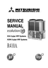
Parts layout on the indoor unit PCB<br />
Model: FDT series<br />
Fan motor<br />
(501, 601)<br />
Power supply PCB<br />
(CNW8)<br />
To power supply PCB<br />
(501, 601) (CNW9)<br />
Connector<br />
(CNT)<br />
Address switch<br />
(SW2)<br />
CNT<br />
CNM2<br />
CNW8<br />
Heat exchanger thermistor,<br />
Return air thermistor<br />
(Thi-R1, Thi-A)<br />
IC9<br />
IC2<br />
CNW9<br />
C2<br />
PC3<br />
X1<br />
CNM3<br />
IC12<br />
CNG<br />
J8<br />
J10<br />
J11<br />
J12<br />
CNR<br />
52X6 52X1 52X2 52X3<br />
C12<br />
C13<br />
PC5<br />
C1<br />
52X4<br />
L1<br />
C58<br />
C3<br />
CNY CNI<br />
IC3<br />
C4<br />
SW2<br />
Heat exchanger<br />
thermistor<br />
(Thi-R2)<br />
CNH CNN1<br />
J9~J11<br />
(SW10)<br />
J1 (SW7-1)<br />
With<br />
None<br />
Input signal - Reverse invalid<br />
Input signal - Rus stop<br />
J2 (SW7-2)<br />
Heating thermostat OFF-Lo<br />
Heating thermostat OFF-Stop, Lo<br />
J3 (SW7-3)<br />
Normal operation operable<br />
Operation permission prohibited<br />
J4 (SW7-4)<br />
Normal<br />
Heating temp. +3<br />
J5 (SW8-1)<br />
Louver free stop control - Invalid<br />
Louver free stop control - Effective<br />
J6 (SW8-2)<br />
Freeze prevention fan control activated.<br />
Freeze prevention fan control deactivated.<br />
(1)<br />
With<br />
None (1)<br />
With<br />
None (1)<br />
With<br />
None (1)<br />
With<br />
None (1)<br />
With<br />
None (1)<br />
● Change by the jumper wire<br />
Name Function<br />
Note (1) “None” means that jumper wire is not provided on the PCB or the<br />
connection is cut<br />
(2) The replacement board is not equipped with jumpers J1 ~ J6. Instead,<br />
SW7 and 8, with the same functions as jumpers J1~J6, are used in the<br />
position where the jumpers were previously. Set SW7 and 8 locally in<br />
accordance with the above table.<br />
Fan motor<br />
(151~401)<br />
C5<br />
- 8 -<br />
52X8-2<br />
CNE<br />
LED2 LED1<br />
ON<br />
1 2 3 4<br />
SW8 SW9<br />
SW10 SW5<br />
J5<br />
J6<br />
J7<br />
J8<br />
ON<br />
1 2 3 4<br />
SW7<br />
C41<br />
J1<br />
J2<br />
J3<br />
J4<br />
SW5-3<br />
KN1<br />
TVS1<br />
CNV<br />
IC8<br />
IC11<br />
J5~J6<br />
(SW8)<br />
DIP switch<br />
(SW5)<br />
F1<br />
F2<br />
52X7<br />
Z2D<br />
Z3D<br />
Z4D<br />
Z5D<br />
J1~J4<br />
(SW7)<br />
DIP switch<br />
(SW9)<br />
CNB<br />
C11<br />
CNW7<br />
L2<br />
C23<br />
TM1<br />
52X8-1<br />
R17<br />
PC2 PC1<br />
Note (1) It is normally ON only in the case of SW9-4.<br />
D2<br />
IC7<br />
To power supply<br />
(CNW7)<br />
R16<br />
ZD1<br />
CNJ<br />
Remote<br />
controller<br />
● Control change switch (SW5, SW9, SW10)<br />
Function of DIP switch SW5 (Usually all turned OFF)<br />
SW9-3<br />
SW9-4<br />
SW10-1 (J9)<br />
Louver motor<br />
Switch Function<br />
ON<br />
OFF<br />
ON Setting time : 1000hrs. (Unit stop)<br />
SW5-4<br />
OFF Setting time : 1000hrs. (Display)<br />
ON Setting time : 600hrs. (Display)<br />
OFF Setting time : 180hrs. (when shipped from factory)<br />
Function of DIP switch SW9 (Usually all turned OFF)<br />
SW10-2<br />
(J10)<br />
Switch Function<br />
OFF<br />
ON<br />
SW10-3<br />
(J11)<br />
ON<br />
OFF<br />
ON<br />
OFF<br />
OFF<br />
ON<br />
OFF<br />
ON<br />
OFF<br />
ON<br />
Emergency operation<br />
Normal<br />
Fan control : Powerful mode<br />
Fan control : Mild mode<br />
Function of DIP switch SW10 (Usually all turned OFF)<br />
Switch Function<br />
Auto swing fanction - None<br />
Auto swing function - With<br />
Remote controller air flow –<br />
Remote controller air flow 1 speed<br />
Remote controller air flow 2 speed<br />
Remote controller air flow 3 speed
Model: FDEN series<br />
Fan motor<br />
CNJ2<br />
CNM3<br />
CNR<br />
CNV<br />
L2<br />
KN1<br />
C57<br />
52X5<br />
52X3<br />
52X2<br />
52X2<br />
52X6<br />
52X4<br />
52X8-2<br />
52X8-1<br />
52X7<br />
PCB power supply connector<br />
(Primary side)<br />
Power supply<br />
CNW1<br />
L3<br />
L1<br />
F1<br />
Connector<br />
(CNT)<br />
CNW0 CNM1<br />
ZNR<br />
CNQ CNT CNH CNN1<br />
Heat exchanger thermistor,<br />
Return air thermistor<br />
(Thl-R1, Thl-A)<br />
J1 (SW7-1)<br />
With<br />
None<br />
Input signal - Reverse invalid<br />
Input signal - Rus stop<br />
J2 (SW7-2)<br />
Heating thermostat OFF-Lo<br />
Heating thermostat OFF-Stop, Lo<br />
J3 (SW7-3)<br />
Normal operation operable<br />
Operation permission prohibited<br />
J4 (SW7-4)<br />
Normal<br />
Heating temp. +3<br />
J5 (SW8-1)<br />
Louver free stop control - Invalid<br />
Louver free stop control - Effective<br />
J6 (SW8-2)<br />
Freeze prevention fan control activated.<br />
Freeze prevention fan control deactivated.<br />
(1)<br />
With<br />
None (1)<br />
With<br />
None (1)<br />
With<br />
None (1)<br />
With<br />
None (1)<br />
With<br />
None (1)<br />
● Change by the jumper wire<br />
Name Function<br />
Note (1) “None” means that jumper wire is not provided on the PCB or the<br />
connection is cut<br />
(2) The replacement board is not equipped with jumpers J1 ~ J6. Instead,<br />
SW7 and 8, with the same functions as jumpers J1~J6, are used in the<br />
position where the jumpers were previously. Set SW7 and 8 locally in<br />
accordance with the above table.<br />
- 9 -<br />
CNE<br />
LED1<br />
LED2<br />
IC7<br />
SW2 SW5<br />
SW10<br />
Address switch<br />
(SW2)<br />
SW9<br />
IC8<br />
SW8<br />
SW7<br />
Heat exchanger thermistor<br />
(Thl-R2)<br />
CNB CNW2<br />
J9~J11<br />
(SW10)<br />
PCB power supply<br />
connector<br />
(Secondary side)<br />
Remote controller<br />
DIP switch<br />
(SW5)<br />
J5, J6<br />
(SW8)<br />
J1~J4<br />
(SW7)<br />
DIP switch<br />
(SW9)<br />
● Control change switch (SW5, SW9, SW10)<br />
Function of DIP switch SW5 (Usually all turned OFF)<br />
Switch Function<br />
SW5-3<br />
ON<br />
OFF<br />
ON Setting time : 1000hrs. (Unit stop)<br />
SW5-4<br />
OFF Setting time : 1000hrs. (Display)<br />
ON Setting time : 600hrs. (Display)<br />
OFF Setting time : 180hrs. (when shipped from factory)<br />
Function of DIP switch SW9 (Usually all turned OFF)<br />
SW9-3<br />
SW9-4<br />
SW10-1 (J9)<br />
Switch Function<br />
OFF<br />
ON<br />
ON<br />
OFF<br />
ON<br />
OFF<br />
OFF<br />
ON<br />
OFF<br />
ON<br />
OFF<br />
ON<br />
Emergency operation<br />
Normal<br />
Fan control : Powerful mode<br />
Fan control : Mild mode<br />
Note (1) It is normally ON only in the case of SW9-4.<br />
Function of DIP switch SW10 (Usually all turned OFF)<br />
SW10-2<br />
(J10)<br />
Switch Function<br />
SW10-3<br />
(J11)<br />
Auto swing fanction - None<br />
Auto swing function - With<br />
Remote controller air flow –<br />
Remote controller air flow 1 speed<br />
Remote controller air flow 2 speed<br />
Remote controller air flow 3 speed
Model: FDKN series<br />
This diagram shows the PCB for the 151~251. The component layout on the 301 PCB is different, but the functions are the<br />
same.<br />
Dip switch<br />
(SW5)<br />
J9~J11<br />
(SW10)<br />
Dip switch<br />
(SW9)<br />
J5~J8<br />
(SW8)<br />
J1~J4(SW7)<br />
Adress switch<br />
(SW2)<br />
CNZ<br />
SW10 SW5<br />
J11<br />
J10<br />
J9<br />
SW8<br />
J8<br />
J7<br />
J6<br />
J5<br />
SW2<br />
SW9<br />
J4<br />
J3<br />
J2<br />
J1<br />
CNE<br />
SW7<br />
IC9 IC10<br />
LED1<br />
CNL<br />
C92<br />
J31<br />
CNG<br />
CNY CNJ<br />
Heat exchanger thermistor<br />
(Thl-R2)<br />
IC8<br />
J31<br />
CNT<br />
Louver motor<br />
J1 (SW7-1)<br />
With<br />
None<br />
Input signal - Reverse invalid<br />
Input signal - Rus stop<br />
J2 (SW7-2)<br />
Heating thermostat OFF-Lo<br />
Heating thermostat OFF-Stop, Lo<br />
J3 (SW7-3)<br />
Normal operation operable<br />
Operation permission prohibited<br />
J4 (SW7-4)<br />
Normal<br />
Heating temp. +3<br />
J5 (SW8-1)<br />
Louver free stop control - Invalid<br />
Louver free stop control - Effective<br />
J6 (SW8-2)<br />
Freeze prevention fan control activated.<br />
Freeze prevention fan control deactivated.<br />
J8 (SW8-4)<br />
Model 151~251<br />
Model 301<br />
(1)<br />
With<br />
None (1)<br />
With<br />
None (1)<br />
With<br />
None (1)<br />
With<br />
None (1)<br />
With<br />
None (1)<br />
With<br />
None (1)<br />
● Change by the jumper wire<br />
Name Function<br />
Note (1) “None” means that jumper wire is not provided on the PCB or the<br />
connection is cut<br />
(2) The replacement board is not equipped with jumpers J1 ~ J8. Instead,<br />
SW7 and 8, with the same functions as jumpers J1~J8, are used in the<br />
position where the jumpers were previously. Set SW7 and 8 locally in<br />
accordance with the above table.<br />
CNN1<br />
L4<br />
- 10 -<br />
CNB<br />
CNH<br />
R62<br />
C2<br />
BZ<br />
IC11<br />
Connector<br />
(CNT)<br />
Heat exchanger thermistor,<br />
Return air thermistor<br />
(Thl-R1, Thl-A)<br />
L1 L2<br />
CNM<br />
R17<br />
CNW1<br />
R16<br />
R151<br />
C104<br />
Fan motor<br />
Remote controller<br />
PCB power supply<br />
connector<br />
(Primary side)<br />
PCB power supply<br />
connector<br />
(Secondary side)<br />
● Control change switch (SW5, SW9, SW10)<br />
Function of DIP switch SW5 (Usually all turned OFF)<br />
Switch Function<br />
SW5-3<br />
ON<br />
OFF<br />
ON Setting time : 1000hrs. (Unit stop)<br />
SW5-4<br />
OFF Setting time : 1000hrs. (Display)<br />
ON Setting time : 600hrs. (Display)<br />
OFF Setting time : 180hrs. (when shipped from factory)<br />
Function of DIP switch SW9 (Usually all turned OFF)<br />
SW9-1<br />
SW9-2<br />
SW9-3<br />
SW9-4<br />
SW10-1 (J9)<br />
Switch Function<br />
OFF<br />
ON<br />
OFF<br />
ON<br />
ON<br />
OFF<br />
ON<br />
OFF<br />
Custom code - Change<br />
Custom code - Normal<br />
Power failure security - Effective<br />
Power failure security - Invalid<br />
Emergency operation<br />
Normal<br />
Fan control : Powerful mode<br />
Fan control : Mild mode<br />
Note (1) It is normally ON only in the case of SW9-4.<br />
Function of DIP switch SW10 (Usually all turned OFF)<br />
SW10-2<br />
(J10)<br />
Switch Function<br />
OFF<br />
ON<br />
SW10-3<br />
(J11)<br />
OFF<br />
ON<br />
OFF<br />
ON<br />
OFF<br />
ON<br />
TB,3<br />
TB,2<br />
TB,1<br />
Auto swing fanction - None<br />
Auto swing function - With<br />
Remote controller air flow –<br />
Remote controller air flow 1 speed<br />
Remote controller air flow 2 speed<br />
Remote controller air flow 3 speed<br />
G
Model: FDUR series<br />
Drain motor<br />
L3<br />
L2<br />
CNJ2 CNR<br />
CNT CNV<br />
52X3<br />
Connector<br />
(CNT)<br />
52X5 52X4<br />
CNO<br />
52X2 52X1 52X6<br />
CNW1 CNM3<br />
Heat exchanger thermistor,<br />
Return air thermistor<br />
(Thl-R1, Thl-A)<br />
PCB power supply connector<br />
(Primary side)<br />
Heat exchanger thermistor<br />
(Thl-R2)<br />
Remote controller<br />
CNH CNN1 CNN2 CNF CNB CNQ<br />
SW2 SW10<br />
F1<br />
CNW0<br />
J1 (SW7-1)<br />
With<br />
None<br />
Input signal - Reverse invalid<br />
Input signal - Rus stop<br />
J2 (SW7-2)<br />
Heating thermostat OFF-Lo<br />
Heating thermostat OFF-Stop, Lo<br />
J3 (SW7-3)<br />
Normal operation operable<br />
Operation permission prohibited<br />
J4 (SW7-4)<br />
Normal<br />
Heating temp. +3<br />
J6 (SW8-2)<br />
Freeze prevention fan control activated<br />
Freeze prevention fan control deactivated<br />
(1)<br />
With<br />
None (1)<br />
With<br />
None (1)<br />
With<br />
None (1)<br />
With<br />
None (1)<br />
● Change by the jumper wire<br />
Name Function<br />
Note (1) “None” means that jumper wire is not provided on the PCB or the<br />
connection is cut<br />
(2) The replacement board is not equipped with jumpers J1 ~ J4, J6.<br />
Instead, SW7 and 8, with the same functions as jumpers J1~J4, J6, are<br />
used in the position where the jumpers were previously. Set SW7 and 8<br />
locally in accordance with the above table.<br />
L1<br />
CNE<br />
CNG<br />
Power supply<br />
CNW2<br />
- 11 -<br />
Address swith<br />
(SW2)<br />
LED2<br />
LED1<br />
DIP switch<br />
(SW5)<br />
J10~J11<br />
(SW10)<br />
L4<br />
SW8 SW9 CNZ CNI<br />
SW5 SW7<br />
CNK1<br />
CNK2<br />
PCB power supply connector<br />
(Secondary side)<br />
DIP switch<br />
(SW9)<br />
J1~J4<br />
(SW7)<br />
F2<br />
J6<br />
(SW8)<br />
F3<br />
CNO<br />
CNA<br />
Float switch<br />
● Control change switch (SW5, SW9, SW10)<br />
Function of DIP switch SW5 (Usually all turned OFF)<br />
Switch Function<br />
SW5-3<br />
ON<br />
OFF<br />
ON Setting time : 1000hrs. (Unit stop)<br />
SW5-4<br />
OFF Setting time : 1000hrs. (Display)<br />
ON Setting time : 600hrs. (Display)<br />
OFF Setting time : 180hrs. (when shipped from factory)<br />
Function of DIP switch SW9 (Usually all turned OFF)<br />
Switch Function<br />
SW9-3<br />
ON<br />
OFF<br />
Emergency operation<br />
Normal<br />
SW9-4<br />
ON<br />
OFF<br />
Fan control : High speed (High Ceiling)<br />
Fan control : Standard<br />
Function of DIP switch SW10 (Usually all turned OFF)<br />
SW10-2<br />
(J10)<br />
Switch Function<br />
OFF<br />
ON<br />
SW10-3<br />
(J11)<br />
OFF<br />
ON<br />
OFF<br />
ON<br />
Remote controller air flow –<br />
Remote controller air flow 1 speed<br />
Remote controller air flow 2 speed<br />
Remote controller air flow 3 speed
(c) Check method when the error code is display<br />
Remote controller or Indication board: Inspection LED, error code<br />
Indoor unit PCB: Red LED (inspection display), Green LED (CPU. normal display)<br />
Outdoor unit PCB: ARed LED (inspection display), Green LED (CPU. normal display)<br />
1 Error display : No display<br />
LCD display : No display<br />
Red LED<br />
Indoor unit<br />
Stays OFF<br />
Green LED Stays OFF<br />
Start<br />
Is the voltage<br />
between 1 and 2/N of the indoor<br />
unit’s terminal block<br />
AC220/240V?<br />
Fuse<br />
OK?<br />
YES<br />
YES<br />
Is the voltage at<br />
CNW3 or 10 (1) (red – red) on the<br />
transformer’s secondary side<br />
14 V or higher?<br />
YES<br />
(1)(2)<br />
Is the voltage NO<br />
between CNW5 2 and 3<br />
DC 12V?<br />
YES<br />
(1)(2)<br />
Is the voltage NO<br />
between CNW8 2 and 3<br />
DC 12V?<br />
YES<br />
NO<br />
[Power supply line error]<br />
Red LED<br />
Outdoor unit<br />
Stays OFF<br />
Green LED Stays OFF<br />
Note (1) The green LED in the outdoor unit is used in the FDCA301 ~ 601 models only.<br />
Does it return<br />
to normal when the power<br />
supply is reset?<br />
Replacement indoor unit<br />
control PCB<br />
NO Voltage between YES<br />
1 and 2/N of the outdoor unit’s<br />
terminal block is<br />
AC220/240V.<br />
NO<br />
NO Disconnect the transformer’s primary side<br />
(CNW1) and measure the resistance on<br />
both ends of CNW1 (using a tester, etc.).<br />
Several 10K Ω or higher.<br />
NO<br />
Notes (1) In models other than FDT, replace the fuse.<br />
(2) FDT only<br />
NO<br />
Note (1) In models other than FDT, it is CNW2.<br />
YES<br />
Outdoor unit check<br />
Transformer exchange<br />
Replacement indoor unit<br />
power supply PCB<br />
Harness disconnection<br />
Note (1) 3 is GND<br />
Unit is normal.<br />
(Malfunction was due to noise, etc.)<br />
- 12 -<br />
Control lines connected<br />
wrong or disconnected.<br />
YES<br />
Fuse exchange<br />
Replacement indoor unit<br />
power supply PCB
Red LED<br />
Indoor unit<br />
3 time flash<br />
Green LED Keeps flashing<br />
Remote<br />
controller wiring<br />
connect check (Red·<br />
White·Black)<br />
OK<br />
Remote controller wire<br />
is removed<br />
Red LED<br />
Outdoor unit<br />
Stays OFF<br />
Green LED Keeps flashing<br />
Note (1) The green LED in the outdoor unit is used in the FDCA301 ~ 601 models only.<br />
(1)<br />
Approximately<br />
10 ~ 11 V between<br />
X and Z.<br />
NO<br />
YES<br />
Remeasure<br />
between X~Z.<br />
10~11V.<br />
NO<br />
NO<br />
YES<br />
Note (1) Z is GND.<br />
(2)<br />
Is the voltage<br />
between CNW8 1-3<br />
12V?<br />
YES<br />
Replacement indoor<br />
unit control PCB<br />
YES<br />
NO<br />
Note (2) 3 is GND.<br />
Correction<br />
Power supply reset<br />
Remote controller wire short circuit?<br />
Remote controller defective<br />
Check the<br />
CNW5-8 harness.<br />
NG<br />
Harness exchange<br />
- 13 -<br />
OK<br />
Normal?<br />
YES<br />
Maltifunction by<br />
accidental noise<br />
NO<br />
Replacement indoor unit power<br />
supply PCB<br />
Remote controller wire<br />
disconnection?<br />
Remote controller defective<br />
Only case of FDT
2 Error display “ WAIT ” Indoor – outdoor communications trouble<br />
(Initial (when the power is turned on)<br />
Indoor unit<br />
Outdoor unit<br />
Red LED<br />
Green LED<br />
Stays OFF<br />
Keeps flashing<br />
Red LED<br />
Green LED<br />
- 14 -<br />
2 time flash<br />
Keeps flashing<br />
Notes (1) If trouble occurs during communications, the error code E5 is displayed (Outdoor, Red LED flashes 2 times). The check procedure is as shown below. (However, excluding<br />
connection related problems) Also, if the power supply is reset after E5 occurs, if the trouble is intermittent, it will be displayed in the LCD(“ WAIT ”).<br />
(2) The green LED in the outdoor unit is used in the FDCA301 ~ 601 models only.<br />
● 151~251 ● 301~601<br />
The remote controller’s LCD(“ WAIT ”)<br />
display remains unchanged after waiting 2<br />
minutes after the power is turned on.<br />
YES<br />
Is the outdoor unit controller's<br />
power fuse F5 (20A) blown?<br />
YES<br />
(1)<br />
Is the voltage at the secondary side<br />
of the noise filter AC220/240V?<br />
YES<br />
(1)<br />
Are the wires connecting to the<br />
noise filter board OK?<br />
YES<br />
Is the indoor unit’s green LED<br />
flashing?<br />
YES<br />
Is the outdoor unit’s control red<br />
LED flashing 2 times?<br />
YES<br />
Are the wires connecting the indoor<br />
and outdoor units connected<br />
according to specifications?<br />
YES<br />
Measure the voltage between 2/N and<br />
3 of the outdoor unit’s terminal block.<br />
DC 20V<br />
Measure the voltage between 2/N and<br />
3 of the indoor unit’s terminal block.<br />
DC 20V<br />
Indoor unit control<br />
PCB defect<br />
YES<br />
YES<br />
YES<br />
NO<br />
NO<br />
NO<br />
NO<br />
NO<br />
NO<br />
Approx.<br />
0V DC<br />
Approx.<br />
0V DC<br />
Inverter check before replacing the power supply fuse.<br />
Is the noise filter out of<br />
phase or short circuited?<br />
Are there any cracks or burnouts in<br />
the power module or diode stack?<br />
Is the reactor abnormal?<br />
Power supply<br />
fuse exchange<br />
NO<br />
NO<br />
NO<br />
Note (1) 1 phase is removed.<br />
Nois filter<br />
exchange<br />
Replacement outdoor<br />
unit control PCB<br />
Reactor<br />
exchange<br />
*<br />
Power supply<br />
fuse exchange<br />
Noise filter<br />
exchange<br />
Connects<br />
corrently<br />
Indoor unit control<br />
PCB defect<br />
Indoor/outdoor unit control PCB<br />
defect Remote controller defect<br />
Remote controller wire<br />
disconnection (Y)<br />
Repair the wires<br />
connecting the indoor<br />
and outdoor units.<br />
Outdoor unit<br />
control PCB defect<br />
Connection wires are<br />
faulty (disconnection)<br />
Noise<br />
The remote controller’s LCD (“ WAIT ”)<br />
display remains unchanged after waiting 2<br />
minutes after the power is turned on.<br />
YES<br />
YES<br />
YES<br />
YES<br />
Is the outdoor green LED<br />
flashing?<br />
YES<br />
Is the indoor green LED<br />
flashing?<br />
Is the outdoor red LED<br />
flashing 2 times?<br />
Are the wires connecting the indoor<br />
and outdoor units connected according<br />
to specifications?<br />
YES<br />
YES YES<br />
YES<br />
Are the wires connecting the indoor<br />
and outdoor units connected according<br />
to specifications?<br />
YES<br />
Measure the voltage between 2/N and<br />
3 of the outdoor unit’s terminal block.<br />
DC 20V<br />
Measure the voltage between 2/N and<br />
3 of the indoor unit’s terminal block.<br />
Approx.<br />
20V DC<br />
Indoor unit control<br />
PCB defect<br />
Remote controller does not display<br />
after the power is turned on.<br />
Is the indoor green LED<br />
flashing?<br />
Is the outdoor red LED<br />
flashing 2 times?<br />
Approx.<br />
0V DC<br />
Approx.<br />
0V DC<br />
NO<br />
NO<br />
NO<br />
NO<br />
NO<br />
NO<br />
NO<br />
Approx.<br />
Measure the voltage between 2/N 0V DC<br />
and 3 of the outdoor unit’s<br />
terminal block.<br />
Approx. 20V DC<br />
Indoor unit control<br />
PCB defect<br />
Indoor unit control PCB<br />
defect<br />
Remote controller defect<br />
Remote controller wire<br />
disconnection (Y)<br />
Repair the wires<br />
connecting the indoor<br />
and outdoor units.<br />
Connection wires are<br />
faulty (disconnection)<br />
Noise<br />
Measure the voltage between 2/N Approx. 0V DC<br />
and 3 of the indoor unit’s<br />
terminal block.<br />
Approx. 20V DC<br />
Indoor unit<br />
control PCB<br />
defect<br />
Outdoor unit<br />
control PCB<br />
defect<br />
Repair the<br />
connection<br />
lines.<br />
The indoor/outdoor<br />
control board is faulty.<br />
The remote controller<br />
is faulty.<br />
The X or Z lines in the<br />
remote controller are<br />
disconnected.<br />
Outdoor unit control<br />
PCB defect<br />
Connection wires are<br />
faulty (disconnection)<br />
Noise<br />
Is the fuse (10A) OK?<br />
(1)<br />
Is the voltage on the outdoor unit’s<br />
transformer secondary side (red –<br />
red) 14 V?<br />
YES<br />
Is the voltage on the outdoor<br />
unit’s transformer secondary<br />
side (red – red) AC15V?<br />
YES<br />
YES<br />
YES<br />
Outdoor unit<br />
control PCB<br />
defect<br />
Is the fuse on the indoor unit<br />
control PCB OK?<br />
Is the voltage between the red and<br />
black wires in the remote<br />
controller DC10~11V when the<br />
remote controller is disconnected?<br />
Remote<br />
controller<br />
defect<br />
NO<br />
NO<br />
NO<br />
NO<br />
NO<br />
Fuse<br />
exchange<br />
Transformer<br />
defect<br />
Fuse<br />
exchange<br />
Transformer<br />
defect<br />
The remote<br />
controller<br />
wires are<br />
short<br />
circuited.
3 Error display : e1 [Communication error between remote controller~Indoor unit]<br />
Red LED<br />
Green LED<br />
Indoor unit<br />
Stays OFF<br />
Keeps flashing<br />
Voltage<br />
between X and Z<br />
approximately<br />
10~11 V?<br />
NO<br />
Voltage<br />
fluctuates between<br />
5~11 V between<br />
Y and Z.<br />
YES<br />
Voltage<br />
fluctuates between<br />
5~10 V between<br />
Y and Z<br />
indoors.<br />
YES<br />
Voltage<br />
fluctuates between<br />
5~10 V between<br />
CNB Y and Z.<br />
YES<br />
Indoor unit<br />
resets every ❇<br />
4 minutes.<br />
YES<br />
YES<br />
NO<br />
NO<br />
NO<br />
NO<br />
Red LED<br />
Green LED<br />
Note (1) The green LED in the outdoor unit is used in the FDCA301 ~ 601 models only.<br />
Red LED<br />
Green LED<br />
Power supply reset<br />
Normal?<br />
NO<br />
Replacement indoor<br />
unit control PCB<br />
Indoor unit<br />
Stays OFF<br />
Stays OFF or Lights<br />
continuously<br />
Replacement remote<br />
controller<br />
Remote controller<br />
wire disconnection<br />
Terminal block CNB<br />
harness is defective.<br />
Outdoor unit<br />
Stays OFF<br />
Keeps flashing<br />
❇ After the green LED lights up once,<br />
it begins flashing again continuously.<br />
The louver moves once in the<br />
close direction.<br />
YES<br />
Power supply reset<br />
Red LED<br />
Noise<br />
Green LED<br />
Power supply OFF<br />
Outdoor unit<br />
Note (1) The green LED in the outdoor unit is used in the FDCA301 ~ 601 models only.<br />
● Only case of FDT<br />
Stays OFF<br />
Is the voltage<br />
between CNW8<br />
2-3 12V?<br />
Lighting YES<br />
Power supply reset<br />
Normal<br />
YES<br />
NO<br />
NO<br />
The unit is normal.<br />
(The malfunction is due to noise, etc.)<br />
Check the CNW5-<br />
CNW8 harness.<br />
Replacement indoor<br />
unit control PCB<br />
- 15 -<br />
Stays OFF<br />
YES<br />
Keeps flashing<br />
Power supply<br />
reset<br />
Normal?<br />
Is the<br />
resistance between<br />
Y~Z on the remote controller<br />
approximately<br />
10kΩ?<br />
NO<br />
Replacement remote<br />
controller<br />
● Cases of other than FDT<br />
Remote controller<br />
wire is removed<br />
Resistance is<br />
approximately 10kΩ<br />
between indoor<br />
Y~Z.<br />
YES<br />
Remote controller<br />
wire short circuit<br />
YES<br />
NO<br />
NO<br />
Disconnection ?<br />
Noise?<br />
NO<br />
Is the<br />
voltage at the transfomer's<br />
secondary side (red-red) 15V<br />
or higher?<br />
YES<br />
Replacement indoor unit<br />
power supply PCB<br />
Is it normalized?<br />
NO<br />
Defective indoor unit control PCB<br />
Replace. (Defective CPU)<br />
YES<br />
Replacement<br />
remote controller<br />
Replacement indoor<br />
unit control PCB<br />
YES<br />
NO<br />
Harness<br />
exchange<br />
Transformer<br />
exchange<br />
Unit is normal.<br />
(Runaway of indoor<br />
unit CPU due to<br />
noise, etc.<br />
Transient trouble)
4 Error display : e6 [Defective indoor unit heat exchanger thermistor]<br />
Indoor unit<br />
Outdoor unit<br />
Red LED<br />
1 time flash Red LED<br />
Stays OFF<br />
Green LED Keeps flashing Green LED Keeps flashing<br />
Note (1) The green LED in the outdoor unit is used in the FDCA301 ~ 601 models only.<br />
Is the indoor<br />
unit heat exchanger<br />
thermistor connector<br />
connection OK?<br />
NO<br />
Correction<br />
YES<br />
Defective indoor unit control PCB<br />
Replace-ment (Defective indoor unit<br />
heat exchanger thermistor input circuit)<br />
YES<br />
Are characteristics<br />
of indoor unit heat<br />
exchanger thermistor OK<br />
or is there any<br />
broken wire?<br />
5 Error display : e7 [Detective return air thermistor]<br />
Indoor unit<br />
Outdoor unit<br />
Red LED<br />
1 time flash Red LED<br />
Stays OFF<br />
Green LED Keeps flashing Green LED Keeps flashing<br />
Note (1) The green LED in the outdoor unit is used in the FDCA301 ~ 601 models only.<br />
Is the return air<br />
thermistor connector<br />
connection OK?<br />
NO<br />
Correction<br />
NO<br />
Defective indoor unit heat exchanger<br />
thermistor Replacement<br />
- 16 -<br />
Resistance (kΩ)<br />
YES<br />
Is the return air<br />
thermistor characteristics<br />
OK or is there a<br />
broken wire?<br />
YES<br />
NO<br />
Defective return air<br />
thermistor Replacement<br />
15<br />
10<br />
5<br />
Return air thermistor (ThI-A)<br />
Indoor unit heat exchanger thermistor<br />
(ThI-R1, R2)<br />
Resistance temperature characteristics<br />
5kΩ at 25˚C<br />
0 10 20 30 40 50<br />
Temperature (˚C)<br />
Note (1) 22.5 kΩ at -6˚C<br />
● Display condition<br />
If a temperature of –50ºC or lower is detected continuously for 5 seconds or longer by the thermistor, the compressor<br />
stops. After a 3 minute delay, the compressor restarts. If this state is detected again within 60 minutes after the<br />
first detection.<br />
Defective indoor unit control PCB<br />
Replacement (Defective return air<br />
thermistor input circuit)<br />
Note (1) Characteristics as per the above<br />
graph.<br />
● Display condition<br />
If a temperature of –50ºC or lower is detected continuously for 5 seconds or longer by the thermistor, the compressor<br />
stops. After a 3 minute delay, the compressor restarts. If this state is detected again within 60 minutes after the<br />
first detection.
6 Error display : e8 [Heating overload]<br />
Indoor unit<br />
Outdoor unit<br />
Red LED<br />
1 time flash Red LED<br />
Stays OFF<br />
Green LED Keeps flashing Green LED Keeps flashing<br />
Note (1) The green LED in the outdoor unit is used in the FDCA301 ~ 601 models only.<br />
Is the air filter clogged?<br />
NO<br />
Are the connections to<br />
the indoor heat exchanger thermistor<br />
OK?<br />
Repair<br />
NO<br />
7 Error display : e9 [Drain trouble]<br />
Indoor unit<br />
Outdoor unit<br />
Red LED<br />
1 time flash Red LED<br />
Stays OFF<br />
Green LED Keeps flashing Green LED Keeps flashing<br />
Note (1) The green LED in the outdoor unit is used in the FDCA301 ~ 601 models only.<br />
Abnormal data check<br />
in remote controller<br />
Is there any<br />
overflow?<br />
YES<br />
Drain motor ON from<br />
remote controller.<br />
DM<br />
operation<br />
YES<br />
Is drain<br />
piping unclogged?<br />
Is the slop OK?<br />
YES<br />
DM check<br />
YES<br />
YES<br />
● Abnormal Temperature Detection<br />
Abnormal stop<br />
Heating is<br />
possible.<br />
56 63<br />
Indoor unit heat exchanger temp. (˚C)<br />
NO<br />
Are the characteristics of<br />
the indoor heat exchanger thermistor<br />
OK?<br />
NO<br />
NO<br />
Clean it.<br />
NO<br />
Defective indoor unit heat<br />
exchanger thermistor<br />
Replacement<br />
DC 12 V<br />
at both terminals<br />
of CNI?<br />
YES<br />
Float switch check<br />
Correction<br />
- 17 -<br />
NO<br />
Notes (1) Check if the overload state exists or not using the following check points.<br />
Is there a short circuit?<br />
Is the indoor heat exchanger dirty or clogged?<br />
Is the outdoor unit’s fan control normal?<br />
Is the indoor or outdoor air temperature too high?<br />
(2) See the figure page 142 for indoor heat exchanger thermistor characteristics.<br />
YES<br />
((<br />
Check the remote controller for abnormal data.<br />
Does the heating<br />
overload state exist?<br />
Replacement indoor<br />
unit PCB<br />
AC 220/240 V<br />
at both terminals<br />
of CNR?<br />
YES<br />
DM check of<br />
motor wiring<br />
NO<br />
Check the cooling system.<br />
NO<br />
YES<br />
Replacement indoor<br />
unit control PCB<br />
Adjust<br />
● Display condition<br />
An abnormal stop occurs if this state is detected 5 times within 60 minutes of the<br />
first detection, or if the overload state is detected continuously for 6 minutes.
8 Error display : e10 [Control of 1 remote controller VS multiple units<br />
Excessive number of units (more than 17 units) ]<br />
Indoor unit<br />
Outdoor unit<br />
Red LED<br />
Stays OFF Red LED<br />
Stays OFF<br />
Green LED Keeps flashing Green LED Keeps flashing<br />
Note (1) The green LED in the outdoor unit is used in the FDCA301 ~ 601 models only.<br />
9 Error display : e16<br />
Are more<br />
than 17 units connected<br />
to a remote<br />
controller?<br />
NO<br />
YES<br />
Defective indoor unit control PCB<br />
Replacement<br />
White is GND.<br />
CNM1<br />
NO<br />
1 and 3 (Red – White)<br />
DC280V?<br />
CNW9<br />
1 and 3<br />
DC15V?<br />
YES YES<br />
YES<br />
(1)<br />
DC 15V<br />
between CNW9- 3 and<br />
CNM2 4 ?<br />
YES<br />
Does the<br />
fan motor turn<br />
smoothly by<br />
hand?<br />
YES<br />
NO<br />
NO<br />
NO<br />
NO<br />
(2)<br />
Is the voltage YES<br />
at CNM2 3 DC 1V<br />
or higher?<br />
Note (2) CNW9- 3 is GND.<br />
Reduce to 16 units<br />
or less<br />
Indoor unit<br />
Outdoor unit<br />
Red LED<br />
Stays OFF Red LED<br />
Stays OFF<br />
Green LED Keeps flashing Green LED Keeps flashing<br />
Note (1) The green LED in the outdoor unit is used in the FDCA301 ~ 601 models only.<br />
S Only case of FDTA501, 601 types<br />
Replacement indoor<br />
unit control PCB<br />
[Fan motor abnormalities]<br />
3 is GND.<br />
Note (1) CNW9- 3 is GND.<br />
Replacement indoor<br />
unit power supply PCB<br />
Secondary<br />
side of transformer<br />
(red-red) 15V<br />
or more<br />
NO<br />
Replacement transformer<br />
Replacement indoor<br />
unit control PCB<br />
Detective fan motor<br />
- 18 -<br />
NO<br />
NO<br />
Abnormal data check<br />
with remote controller<br />
After check reset,<br />
fan runs on weak.<br />
Fan ON?<br />
YES<br />
Was it reproduced?<br />
YES<br />
When the<br />
motor is turning, does<br />
the voltage at CNM2 2<br />
fluctuate between<br />
0 ~ 15 V?<br />
YES<br />
Replacement indoor<br />
unit control PCB<br />
NO<br />
Check the<br />
circumstances.<br />
● Display conditions<br />
If an indoor unit fan motor’s speed is detected to be less than<br />
200 rpm continuously for 30 seconds, the fan motor stops for 2<br />
seconds. After 2 seconds, it starts again, but this occurs 4 times<br />
within a period of 1 hour.
S Only case of FDKN<br />
Only case of 151~251 types<br />
CNM<br />
1 and 3 (Red – Black)<br />
DC280V?<br />
CNM<br />
4 and 3 (White-Black)<br />
DC15V?<br />
YES<br />
Does the<br />
fan motor turn<br />
smoothly by<br />
hand?<br />
YES<br />
NO<br />
NO<br />
YES YES<br />
NO<br />
NO<br />
Replacement indoor<br />
unit control PCB<br />
Secondary<br />
side of transformer<br />
(red-red) 14V<br />
or more<br />
(2)<br />
Is the voltage<br />
at CNM 5 (Yellow) DC 1V<br />
YES<br />
or higher?<br />
Note (2) CNM 3 (Black) is GND.<br />
Replacement indoor<br />
unit control PCB<br />
Only case of 301 type<br />
CNM<br />
1 and 4 (Red-Blue)<br />
DC 0~60V ?<br />
NO<br />
Turn the power off and wait<br />
a short time (30 min. ~ 1 hr.)<br />
YES<br />
When tried again,<br />
the fan goes ON.<br />
YES<br />
Replacement indoor<br />
unit control PCB<br />
3 (Black) is GND.<br />
3 (Black) is GND.<br />
3 (black) is GND.<br />
YES<br />
YES<br />
NO<br />
Replacement transformer<br />
Detective fan motor<br />
Replacement fan<br />
motor<br />
Check the<br />
circumstances.<br />
- 19 -<br />
NO<br />
NO<br />
Abnormal data check<br />
with remote controller<br />
After check reset,<br />
fan runs on Me.<br />
Fan ON?<br />
YES<br />
Was it reproduced?<br />
YES<br />
YES<br />
NO<br />
Check the<br />
circumstances.<br />
When the (1)<br />
motor is turning, does<br />
the voltage at CNM 6 (Blue)<br />
fluctuate between<br />
DC 0 ~ 15 V?<br />
Note (1) CNM 3 (Black) is GND.<br />
Replacement indoor<br />
unit control PCB<br />
● Display conditions<br />
If an indoor unit fan motor’s speed is detected to be less than<br />
200 rpm continuously for 30 seconds, the fan motor stops for 2<br />
seconds. After 2 seconds, it starts again, but this occurs 4 times<br />
within a period of 1 hour.<br />
NO<br />
NO<br />
After check reset,<br />
fan runs on Me.<br />
Fan ON ?<br />
YES<br />
Was it reproduced?<br />
YES<br />
When (1)<br />
the motor is turning,<br />
does the voltage at CNM 5<br />
(White) fluctuate between<br />
DC 0 ~ 15 V?<br />
YES<br />
Replacement indoor<br />
unit control PCB<br />
NO<br />
NO<br />
Check the<br />
circumstances.<br />
Replacement fan<br />
motor<br />
Note (1) CNM 4 (Blue) is GND.<br />
● Display conditions<br />
If an indoor unit fan motor’s speed is detected to be less than<br />
200 rpm continuously for 30 seconds, the fan motor stops for 2<br />
seconds. After 2 seconds, it starts again, but this occurs 4 times<br />
within a period of 1 hour.
10<br />
Error display : e28 [Directive remote controller thermistor.]<br />
Indoor unit<br />
Outdoor unit<br />
Red LED<br />
Stays OFF Red LED<br />
Stays OFF<br />
Green LED Keeps flashing Green LED Keeps flashing<br />
Note (1) The green LED in the outdoor unit is used in the FDCA301 ~ 601 models only.<br />
Is the remote controller<br />
thermistor connector connection<br />
OK?<br />
NO<br />
Correction<br />
YES<br />
Are characteristics of<br />
remote controller therm-<br />
istor OK or is there any<br />
broken wire?<br />
- 20 -<br />
NO<br />
Detective remote controller<br />
thermistor Replacement<br />
YES<br />
Detectivie remote controller PCB<br />
Replacement (Detective remote<br />
thermistor input circuit)<br />
Resistance-temperature characteristic of remote controller thermister<br />
Temperrature(°C) Resistance value (kΩ) Temperrature(°C) Resistance value (kΩ) Temperrature(°C) Resistance value (kΩ) Temperrature(°C) Resistance value (kΩ)<br />
0<br />
65<br />
14<br />
33<br />
30<br />
16<br />
46<br />
8.5<br />
1<br />
62<br />
16<br />
30<br />
32<br />
15<br />
48<br />
7.8<br />
2<br />
59<br />
18<br />
27<br />
34<br />
14<br />
50<br />
7.3<br />
4<br />
53<br />
20<br />
25<br />
36<br />
13<br />
52<br />
6.7<br />
6<br />
48<br />
22<br />
23<br />
38<br />
12<br />
54<br />
6.3<br />
8<br />
44<br />
24<br />
21<br />
40<br />
11<br />
56<br />
5.8<br />
10<br />
40<br />
26<br />
19<br />
42<br />
9.9<br />
58<br />
5.4<br />
12<br />
36<br />
28<br />
18<br />
44<br />
9.2<br />
60<br />
5.0
(4) Error diagnosis procedures at the outdoor units side<br />
At the error diagnosis related to the outdoor unit, check at first the error code of remote controller and the illumination patterns of<br />
norma1 and inspection display lamps in the same manner as the case of indoor unit.<br />
Then estimate the outline, the cause and the location of error based on the pattern and proceed to the inspcetion and repair.<br />
Since the self diagnosis function by means of the microcomputers of indoor/outdoor units provide the judgement of error of<br />
microcomputers them selves irregularity power supply line, overload, etc. caused by the installation space, inadequate volume of<br />
refrigerant etc., the location and cause of trouble will be discovered without difficulty.<br />
In addition, the display lamps error code of indoor/outdoor unit is kept flashing, (except when the power supply is iterrupted) after<br />
the irregularity is automatically recovered to give irregularity information to the service presonnel. If any mode of higher priority<br />
than the error retained in memory occurs after the reset of error, it is switched to that mode and saved in the memory.<br />
(a) Replacement parts assembly related to the outdoor unit controller<br />
Outdoor unit PCB, power transistor module, capacitor, noise filter, thermistor, (heat exchanger, discharge pipe, outdoor<br />
temperature, power transistor), fuse, transformer, etc.<br />
(b) Replacement procedure of outdoor unit microcomputer printed circuit board.<br />
Microcomputer printed circuit board can replaced with following procedure.<br />
1) Confirm the parts numbers. (Refer to the following parts layout drawing for the location of parts number.)<br />
Parts No.<br />
PCA505A080Z<br />
PCA505A065ZN<br />
PCA505A065ZS<br />
Applicable Model<br />
FDCVA151HEN, 201HEN, 251HEN<br />
FDCA301HEN, 401HEN<br />
FDCA301HES, 401HES, 501HES, 601HES<br />
2) Set the model using the model setting switch (SW6). (In the case of the 151~251 only).<br />
Switch Setting Table (All switches are set in the OFF position when shipped from the factory.)<br />
Model 151 201 251<br />
Switch Setting Table<br />
Set the switches ON or<br />
OFF for each switch<br />
No.<br />
( ON, OFF)<br />
Model<br />
Setting Value (A)<br />
Switch Setting Table<br />
Set the switches ON or<br />
OFF for each switch<br />
No.<br />
( ON, OFF)<br />
ON<br />
ON<br />
1 2 3 4<br />
17 10 27<br />
1 2 3 4 5 6<br />
ON<br />
ON<br />
1 2 3 4<br />
301HEN 301HES 401HEN 401HES 501HES 601HES<br />
1 2 3 4 5 6<br />
ON<br />
ON<br />
1 2 3 4<br />
3) Set the overcurrent value using the overcurrent setting switch for CM (SW3). (In the case of the 301~601 only)<br />
Switch Setting Table (All switches are set in the OFF position when shipped from the factory.)<br />
1 2 3 4 5 6<br />
ON<br />
11 12 14<br />
1 2 3 4 5 6<br />
ON<br />
4) Set the control select switch to match the previously set settings on the previous board.<br />
If the previously set settings were set with jumper wires, the control select switch should be set in the ON position if there<br />
was a jumper wire and in the OFF position if there wasn’t a jumper wire.<br />
5) Connect the faston terminals and connectors to the control board.<br />
When connecting the wires to the faston terminals, connect each wire to the terminal printed with the same color on the<br />
board.<br />
Note (1) When connecting the faston terminals to the control board, connect them so that there is no deformation of the far end of the circuit board.<br />
- 21 -<br />
1 2 3 4 5 6<br />
ON<br />
1 2 3 4 5 6
Parts layout on the outdoor unit PCB<br />
S FDCVA151~251 type<br />
CN<br />
F2<br />
W<br />
V<br />
U<br />
T8<br />
CNI<br />
T7<br />
T6<br />
T5<br />
T2 F1<br />
T4<br />
Power transistor thermistor<br />
(Tho-IPM)<br />
● Change by the jumper wire<br />
Model 151 201 251<br />
JA1 (SW7-1) None None None<br />
JA5 (SW6-1) None None None<br />
JA6 (SW6-2) None With None<br />
JA7 (SW6-3) None None With<br />
JA8 (SW6-4) With With With<br />
Sub PCB<br />
(Noise filter)<br />
● Function of DIP switches (SW5) (Usually all turned OFF)<br />
Switch Function<br />
SW5-1<br />
ON Defrost Setting Select For cold regions.<br />
OFF Normal<br />
SW5-2<br />
ON<br />
OFF<br />
Snow-guard fan control-Effective<br />
Snow-guard fan control-Invalid<br />
SW5-3<br />
ON Low refrigerant protection control-Effective<br />
OFF Low refrigerant protection control-Invalid<br />
SW5-4<br />
ON Test run operation-Heating<br />
OFF Test run operation-Cooling<br />
External PCB<br />
SW5<br />
1 2 3 4<br />
SW5 SW9<br />
Test run operation switch<br />
SW9<br />
CNQ1<br />
T1<br />
Reactor<br />
- 22 -<br />
F3<br />
DIP switch<br />
(SW6)<br />
CNQ<br />
Fan motor<br />
Stepping motor<br />
CNM<br />
SW7<br />
SW6<br />
CNV1<br />
CNE<br />
CNI3<br />
CNI2<br />
CNW<br />
DIP switch<br />
(SW7)<br />
CNL CNTR<br />
Outdoor air temp. thermistor,<br />
Outdoor heat exchanger themistor,<br />
Discharge pipe thermistor<br />
(Tho-A, Tho-R, Tho-D)<br />
Notes (1) “None” means that jumper wire is not provided on the PCB or the connection is cut<br />
Notes (2) The replacement PCB is not equipped with jumper wires JA1 and JA5~JA8. Instead, SW6 and 7<br />
are mounted in the same position and have the same functions as jumper wires JA1 and JA5~JA8.<br />
Carry out the local settings in accordance with the table using SW6 and 7.<br />
● Change by the JA3<br />
Switch Function<br />
JA3<br />
(SW7-3)<br />
with<br />
None<br />
Model selection-Energy saving<br />
Model selection-Standerd<br />
Note (1) “None” means that jumper wire is not provided on the<br />
PCB or the connection is cut.
S FDCA301~601 type<br />
Outdoor air thermistor,<br />
Outdoor heat exchanger<br />
thermistor,<br />
Discharge pipe thermistor<br />
(Tho-A, Tho-D, Tho-R1, 2)<br />
SW3<br />
SW6<br />
SW5<br />
SW4<br />
SW2<br />
(Test run operation switch)<br />
SW5<br />
L11<br />
CNL<br />
SW6<br />
CT1<br />
L12<br />
C6<br />
L6<br />
C7<br />
L7<br />
C6<br />
C8<br />
L8<br />
C9<br />
L10<br />
C10<br />
J4<br />
J3<br />
J2<br />
J1<br />
CT2<br />
C13<br />
J16<br />
J15<br />
J14<br />
J13<br />
J12<br />
J11<br />
J8<br />
J7<br />
J6<br />
J5<br />
1 2 3 4<br />
Stepping motor<br />
SW3<br />
SW4<br />
L5<br />
IC12<br />
C11<br />
C12<br />
C5<br />
SW2<br />
KN1<br />
Fan motor<br />
C4<br />
LED-R<br />
LED-G<br />
CNM1<br />
CNM2<br />
Notes (1) “None” means that jumper wire is not provided on the<br />
PCB or the connection is cut<br />
Notes (2) The replacement board is not equipped with jumper<br />
wires JA1~JA8. Instead, SW4 and 6 are mounted in<br />
the same position and have the same functions as<br />
jumper wires JA1~JA8. Carry out the local settings in<br />
accordance with the above table using SW4 and 6.<br />
CNQ<br />
CNE<br />
HT1<br />
C2<br />
X04 X03 X02<br />
CNM3<br />
CNM4<br />
CNV1<br />
- 23 -<br />
CNA2<br />
C1<br />
C3<br />
X07 X05 X01 X06<br />
PCB power supply connector<br />
(Secondary side)<br />
KN2<br />
CNA1<br />
CNS CNO<br />
Capacitor for FMo<br />
CNW<br />
CNP2<br />
CNP1<br />
CNP3<br />
CNR<br />
Outdoor unit power supplly<br />
PCB power supply connector<br />
(Primary side)<br />
High pressure switch<br />
(63H1)<br />
Crankcase heater<br />
Magnetic contactor<br />
(52C)<br />
4 way valve<br />
J1 with 1 Phase<br />
(SW4-1) None 3 Phase<br />
Cooling<br />
Heating<br />
Defrost recovery temperature 14ºC<br />
Defrost recovery temperature (See page 88)<br />
Defrost prohibited temperature 45 min.<br />
Defrost prohibited temperature 37 min.<br />
(1)<br />
J2 with<br />
(SW4-2) None (1)<br />
J6 with<br />
(SW6-2) None (1)<br />
J7 with<br />
(SW6-3) None<br />
J8<br />
(SW6-4)<br />
(1)<br />
None (1)<br />
● Change by the jumper wire ● Function of DIP switches (SW5) (Usually all turned OFF)<br />
Switch Function<br />
-<br />
Switch Function<br />
ON Defrost Setting Select For cold regions.<br />
SW5-1<br />
OFF Normal<br />
ON Snow-guard fan control-Effective<br />
SW5-2<br />
OFF Snow-guard fan control-Invalid<br />
ON Low refrigerant protection control-Effective<br />
SW5-3<br />
OFF Low refrigerant protection control-Invalid<br />
ON Test run operation-Heating<br />
SW5-4<br />
OFF Test run operation-Cooling<br />
Model 301HEN 301HES 401HEN 401HES 501HES 601HES<br />
Setting Value (A) 17 10 27 11 12 14<br />
With<br />
None (1)<br />
None (1)<br />
With<br />
None (1)<br />
None (1)<br />
With<br />
None (1)<br />
J11 (SW3-1)<br />
With With<br />
J12 (SW3-2)<br />
With With<br />
J13 (SW3-3)<br />
With<br />
None With<br />
(1)<br />
With<br />
None (1)<br />
● Overcurrent Setting<br />
With<br />
Notes (1) “None” means that jumper wire is not provided on the PCB or the<br />
connection is cut<br />
Notes (2) The replacement board is not equipped with jumper wires J11~J13.<br />
Instead, SW3 is mounted in the same position and has the same functions<br />
as jumper wires J11~J13. Carry out the local settings in accordance<br />
with the above table using SW3.<br />
(3) The overcurrent setting value becomes the above setting value (A)<br />
automatically in accordance with the settings on J11(SW3-1) ~<br />
J13(SW3-3) and J1(SW4-1).
- 24 -<br />
Outdoor Unit controller failure diagnosis circuit diagram<br />
FDCVA151~251 type<br />
● Outdoor unit check points<br />
Check items with the *mark when the power is ON.<br />
❇<br />
Power Supply Check<br />
Measure the power supply at L.N.<br />
(It is normal if it is AC 220/240V.)<br />
L<br />
N<br />
E<br />
TB Red<br />
TB<br />
White<br />
Y/NG<br />
F5 (20A)<br />
Fuse Check: There should be<br />
continuity.<br />
Noise Filter Check:<br />
There should be continuity.<br />
There should be no shorts between phases.<br />
T21<br />
T24<br />
T22<br />
T25<br />
Sub PCB<br />
(Noise filter) T26<br />
T30<br />
CNI1 T28 T27<br />
CNI2 CNI3 T2 T4<br />
1 2 3 4 6<br />
FM0<br />
Orange<br />
DC280V<br />
Gray To indoor unit<br />
Brown<br />
F3 (250V 1A)<br />
Orange<br />
DC Reactor Continuity<br />
Check: 50 mΩ or higher,<br />
less than 100 mΩ.<br />
Yellow<br />
T1 T5<br />
Control PCB<br />
When the outdoor<br />
unit fan motor is<br />
abnormal:<br />
(Refer to page 157)<br />
Red<br />
Power transistor module<br />
check: Is there a short circuit,<br />
open circuit or damage?<br />
(See 160 page for the<br />
check procedure.)<br />
LED1<br />
Red<br />
CM<br />
White<br />
Black<br />
U V W<br />
T6 T7 T8<br />
Power transistor module<br />
F2 (250V 20A)<br />
LED1 (Red) Check<br />
Light continuously : Normal<br />
Keeps flashing : EEV<br />
1~3 time flash : Refer to 131 page<br />
Thermistor resistance (kΩ) [T> =80˚C]<br />
CnTR<br />
Power transistor thermistor temperature and<br />
resistance characteristics check<br />
100<br />
50<br />
T< 80˚C<br />
T >80˚C<br />
0<br />
0 20 50 80 100 120<br />
Temperature [ T ] (˚C)<br />
Fuse Check: There should be continuity.<br />
If faulty, replace the control PCB.<br />
10<br />
5<br />
0 Thermistor resistance (kΩ) [T<<br />
=80˚C]
1 Error display : e5 [Communications error during operation]<br />
Indoor unit<br />
Outdoor unit<br />
Red LED<br />
2 time flash Red LED<br />
2 time flash<br />
Green LED Keeps flashing Green LED Keeps flashing<br />
Note (1) The green LED in the outdoor unit is used in the FDCA301 ~ 601 models only.<br />
Is the connection<br />
of the signal wires at the<br />
outdoor unit poor?<br />
YES<br />
(1) (2)<br />
NO<br />
Is the connection<br />
of the signal wires at the<br />
indoor unit poor?<br />
Repair Repair<br />
NO Reset power<br />
Did the remote “ WAIT ” “ WAIT ”<br />
controller’s LCD return<br />
supply.<br />
to normal?<br />
Go to display diagnosis (page 140).<br />
YES YES<br />
The unit is normal.<br />
Malfunction was due to<br />
transient noise, etc.<br />
Notes (1) Check for poor connections (disconnection, looseness) on the outdoor unit’s terminal block.<br />
(2) Check for poor connections or disconnection of the signal lines between the indoor and outdoor units.<br />
Red LED<br />
Green LED<br />
Indoor unit<br />
2 time flash<br />
Keeps flashing<br />
Red LED<br />
Outdoor unit<br />
Stays OFF<br />
Green LED Keeps flashing<br />
Note (1) The green LED in the outdoor unit is used in the FDCA301 ~ 601 models only.<br />
Reset power supply. Did it return to normal?<br />
NO<br />
Outdoor unit’s control PCB is<br />
faulty. (Network communications<br />
circuit is faulty.) Replace<br />
- 25 -<br />
YES<br />
Malfunction is due to noise, etc.<br />
(The outdoor unit’s CPU went<br />
out of control due to noise during<br />
power on.)<br />
2 Error display : e32 [Power supply phases reversed] [Only case of 301~601 type]<br />
Red LED<br />
Green LED<br />
Indoor unit<br />
Stays OFF<br />
Keeps flashing<br />
Are the power supply<br />
phases reversed?<br />
NO<br />
Are the connections<br />
to the reverse phase detection<br />
circuit lines correct?<br />
YES<br />
YES<br />
NO<br />
Outdoor unit’s control PCB is faulty.<br />
Replace<br />
(Reverse phase detection circuit is faulty.)<br />
Red LED<br />
Outdoor unit<br />
1 time flash<br />
Green LED Keeps flashing<br />
Repair<br />
Repair
3 Error display : e33 [Inverter primary current abnormal] [Only case of 151~251 type]<br />
Red LED<br />
Green LED<br />
Indoor unit<br />
Stays OFF<br />
Keeps flashing<br />
Is the power supply normal?<br />
YES<br />
Is the voltage within<br />
the specified range?<br />
YES<br />
NO<br />
NO<br />
Is there any foreign matter NO<br />
such as dust or dirt on the control<br />
PCB soldered surfaces?<br />
YES<br />
Replace the control PCB.<br />
Red LED<br />
Restore it to the<br />
normal state.<br />
Restore it to the<br />
normal state.<br />
Remove any foreign matter<br />
such as dust or dirt.<br />
Outdoor unit<br />
1 time flash<br />
[Compressor overcurrent trouble] [Only case of 301~601 type]<br />
Red LED<br />
Green LED<br />
Is the voltage<br />
AC220/240V between the<br />
L1 and L3 phases and between the L2<br />
and L3 phases on the 52C<br />
secondary side?<br />
YES<br />
Is there overcurrent<br />
at the compressor?<br />
NO<br />
Indoor unit<br />
Stays OFF<br />
Keeps flashing<br />
(1)<br />
Outdoor unit control PCB is<br />
faulty. Replace<br />
(The CT input circuit is faulty.)<br />
NO<br />
YES<br />
Red LED<br />
Outdoor unit<br />
1 time flash<br />
Green LED Keeps flashing<br />
Out of phase between the<br />
L1 and L2 phases.<br />
• Is the power supply voltage proper? (Isn’t it too low?)<br />
• Are the power lines proper? (Aren’t they too thin?)<br />
• Is the overcurrent setting correct? (SW3 setting)<br />
• Is the compressor running with an overload?<br />
• Is the compressor locked?<br />
● Display Conditions<br />
If the inverter’s primary current exceeds the set value for 3 seconds,<br />
the compressor stops. After a 3 minute delay, it restarts, but<br />
when this occurs 5 times within 60 minutes.<br />
- 26 -<br />
• 52C is faulty.<br />
• There is a disconnection between<br />
52C and CM or in the L1 and L2<br />
phases between TB1 and 52C.<br />
Check the unit side.<br />
• During cooling: Is FMo turning?<br />
• During heating: Is FMI turning?<br />
Is the service valve (gas side) fully open?<br />
Is the filter clogged?<br />
• Is there an overcharge?<br />
• Is the installation space for the indoor and<br />
outdoor units proper?<br />
• Is there a short circuit in the indoor or outdoor units?<br />
• Compressor is faulty. Replace<br />
Notes (1) Measure the overcurrent value to make sure.<br />
Also make sure the overcurrent setting set with SW3 and SW4-1 on the outdoor unit control PCB<br />
is not incorrect.
4<br />
5<br />
Error display : e34<br />
Red LED<br />
Green LED<br />
Indoor unit<br />
Stays OFF<br />
Keeps flashing<br />
52C<br />
secondary side L3 phase<br />
open?<br />
NO<br />
(1)<br />
[Open phase at L3 phase of 52C secondary side] (Only case of 301~601 type)<br />
YES<br />
The outdoor unit control PCB is faulty.<br />
(The CT circuit is faulty) Replace<br />
Error display : e35<br />
Red LED<br />
Outdoor unit<br />
1 time flash<br />
Green LED Keeps flashing<br />
(2)<br />
Repair<br />
[Cooling overload operation]<br />
Indoor unit<br />
Outdoor unit<br />
Red LED<br />
Stays OFF Red LED<br />
1 time flash<br />
Green LED Keeps flashing Green LED Keeps flashing<br />
Note (1) The green LED in the outdoor unit is used in the FDCA301 ~ 601 models only.<br />
Are the<br />
characteristics of the<br />
outdoor heat exchanger thermistor<br />
normal?<br />
NO<br />
Replace the outdoor heat<br />
exchanger thermistor.<br />
Is the unit normal?<br />
NO<br />
Abnormal Temperature Detection<br />
Error stop<br />
Return<br />
48 65<br />
Outdoor air temp. (ºC)<br />
(1)<br />
Note (1) In the case of the 151 ~<br />
251, the abnormal stop<br />
temperature differs<br />
depending on the<br />
compressor’s speed.<br />
YES<br />
Is there cooling overload<br />
operation?<br />
Is high pressure control<br />
normal?<br />
Abnormal temperature detection<br />
Is it (the actual measurement) correct?<br />
NO<br />
The outdoor control PCB<br />
is faulty. Replace<br />
Compressor speed<br />
(rps)<br />
less than 88<br />
88 to less than 108<br />
108 or higher<br />
Indoor heat exchanger<br />
temprature (˚C)<br />
65 or more<br />
60 or more<br />
55 or more<br />
- 27 -<br />
AAAAAAAAAAAAAAAAAAAAAAAA<br />
AAA<br />
Notes (1) Also check if there is voltage at the L3 phase on the 52C primary<br />
side, but no voltage on the secondary side (coil wire disconnection<br />
or faulty contacts).<br />
(2) If there is voltage at the L3 phase on the 52C primary side and it<br />
is not abnormal, the outdoor unit control PCB is faulty.<br />
If the unit is operated with the service valve closed, 49C (internal thermostat)<br />
operates. E34 may also be displayed. Check the service valve.<br />
AAAAAAAAAAAAAAAAAAAAAAAA<br />
Check the unit side.<br />
• Is there a short circuit in the outdoor unit?<br />
• Is the installation space proper?<br />
• Is the refrigerant level too high?<br />
• Is the heat exchanger dirty or clogged?<br />
(1) The compressor’s speed drops when all the following conditions are met<br />
(151~251). In the case of the 301~601, expansion valve control is performed.<br />
1Outdoor heat exchanger temperature: A˚C or higher<br />
2Outdoor air temperature: 41ºC or higher<br />
3The outdoor unit’s fan runs at 7 speed (UHi)<br />
A B<br />
58.5 53.5<br />
53.5 48.5<br />
48.5 43.5<br />
58 53<br />
(1) continuously for<br />
30 seconds or longer.<br />
(2) Control is cancelled when the temperature drops to BºC or lower.<br />
Model<br />
Item<br />
Compressor less than 88<br />
151~251 type speed 88 to less than 108<br />
(rps)<br />
108 or higher<br />
301~601 type<br />
Note (1) Values in ( ) show for the case of the 301~601 models.<br />
● Display Conditions<br />
If the outdoor heat<br />
exchanger temperature<br />
becomes 65ºC 5 times<br />
within 60 minutes,<br />
including while the<br />
compressor is stopped,<br />
or if it continues at that<br />
temperature for 10<br />
minutes or longer.<br />
Resistance(kΩ)<br />
15<br />
10<br />
5<br />
Outdoor unit heat exchanger<br />
themistor (Tho-R)<br />
Resistancetemperature characteristics<br />
5kΩ at 25°C<br />
0 10 20 30 40 50<br />
Temperature (°C)<br />
AAA
6<br />
7<br />
Error display : e36<br />
Is the<br />
discharge pipe thermistror<br />
characteristics<br />
normal?<br />
NO<br />
Discharge pipe thermistor<br />
replacement<br />
Is the unit<br />
normalized<br />
NO<br />
Error display : e37<br />
[Defective outdoor unit heat exchanger thermistor]<br />
Indoor unit<br />
Outdoor unit<br />
Red LED<br />
Stays OFF Red LED<br />
1 time flash<br />
Green LED Keeps flashing Green LED Keeps flashing<br />
Note (1) The green LED in the outdoor unit is used in the FDCA301 ~ 601 models only.<br />
Is the outdoor<br />
unit heat exchanger<br />
thermistor connector<br />
OK?<br />
Repair<br />
NO<br />
YES<br />
Abnormal Temperature Detection<br />
151~251 type 301~601 type<br />
Operoble Operoble<br />
YES<br />
[Discharge temperature error]<br />
Indoor unit<br />
Outdoor unit<br />
Red LED<br />
Stays OFF Red LED<br />
1 time flash<br />
Green LED Keeps flashing Green LED Keeps flashing<br />
Note (1) The green LED in the outdoor unit is used in the FDCA301 ~ 601 models only.<br />
Discharge<br />
temperature error?<br />
(At cooling/heating<br />
operation)<br />
Is discharge temperature<br />
control normal?<br />
Abnormal temperature sensed<br />
Is the (actual measurement) normal?<br />
NO<br />
Defective outdoor unit PCB<br />
Replacement<br />
Error stop Error stop<br />
80 105<br />
80 121<br />
Discharge pipe temp. (°C) Discharge pipe temp. (°C)<br />
Are the outdoor unit<br />
heat exchanger thermistor<br />
characteristics OK, is there<br />
any broken wire?<br />
Check the unit side.<br />
Insufficient refrigerant<br />
Charge the refrigerant (measure)<br />
Is it the oveload operation?<br />
● Display conditions<br />
If the discharge temperature is as shown at left 2 (5) times within 60<br />
minutes, or continuously for 60 minutes, including when the compressor<br />
is stopped.<br />
Note (1) Values in ( ) show for the case of the 301~601 models.<br />
NO<br />
Defective outdoor unit<br />
heat exchanger<br />
thermistor Replacement<br />
● Display conditions<br />
If the temperature sensed by the thermistor is –30ºC or lower continuously<br />
for 5 seconds between 2 minutes and 2 minutes 20 seconds<br />
after the compressor goes ON, the compressor stops. After a 3 minute<br />
delay, the compressor restarts. If this state is detected 3 times in 40<br />
(60) minutes.<br />
Note (1) Values in ( ) show for the case of the 301~601 models.<br />
Thermistor resistance<br />
- 28 -<br />
YES<br />
Defective outdoor unit control<br />
PCB Replacement (Defective<br />
outdoor unit heat exchanger<br />
thermistor input circuit)<br />
Outdoor unit heat exchanger<br />
thermistor (ThO-R)<br />
Resistance temperature characteristics<br />
Resistance(kΩ)<br />
Check the unit side.<br />
During cooling: Is FM0 operating?<br />
During heating: Is FM1 operating?<br />
Are service valves (both liquid,<br />
gas) fully opened during both<br />
cooling and heating.<br />
Is the installation space of indoor/<br />
outdoor unit adequate?<br />
Is there any short circuit air flow<br />
for indoor/outdoor units?<br />
If the discharge pipe temperature exceeds the set value,<br />
the compressor’s speed (151~251) or the expansion<br />
valve’s opening angle (301~601) is controlled to prevent<br />
the discharge pipe temperature from rising.<br />
Compressor control The compressor’s capacity<br />
is lowered (Each minute the<br />
speed is reduced (151~251).<br />
Hold<br />
Expansion valve control<br />
(301~601)<br />
Release<br />
151~251 type 80 90<br />
301~601 type 90 100<br />
Discharge pipe temperature (°C)<br />
● 151~251 type ● 301~601 type<br />
Temperature-resistance characteristics<br />
of discharge pipe thermistor (Tho-D)<br />
100<br />
50<br />
0<br />
0<br />
Thermistor resistance (kΩ)[T < 80°C]<br />
Temperature-resistance characteristics<br />
of discharge pipe thermistor (Tho-D)<br />
100<br />
10<br />
0<br />
20 40 60 80 100 120 140 0 50 80 100<br />
Temperature [T] (°C) Temperature [T] (°C)<br />
15<br />
10<br />
50<br />
5<br />
T80˚C<br />
5kΩ at 25°C<br />
0 10 20 30 40 50<br />
Temperature (°C)<br />
5<br />
0<br />
Thermistor resistance (kΩ)[T > 80°C]
8<br />
9<br />
Error display : e38<br />
Is the outdoor<br />
air temperature thermistor<br />
connector connection<br />
OK?<br />
NO<br />
Repair<br />
YES<br />
Is the outdoor<br />
air temperature thermistor<br />
characteristics OK, is there<br />
no broken wire?<br />
YES<br />
NO<br />
Defective outdoor air<br />
temperature thermistor<br />
Replacement<br />
● Display conditions<br />
If the temperature sensed by the thermistor is –30ºC or lower continuously<br />
for 5 seconds between 2 minutes and 2 minutes 20 seconds after<br />
the compressor goes ON, the compressor stops. After a 3 minute delay,<br />
the compressor restarts. If this state is detected 3 times in 40 (60) minutes.<br />
Note (1) Values in ( ) show for the case of the 301~601 models.<br />
Error display : e39<br />
[Defective discharge pipe thermistor]<br />
Indoor unit<br />
Outdoor unit<br />
Red LED<br />
Stays OFF Red LED 1 time flash<br />
Green LED Keeps flashing Green LED Keeps flashing<br />
Note (1) The green LED in the outdoor unit is used in the FDCA301 ~ 601 models only.<br />
Is the discharge<br />
pipe thermistor<br />
connector connection<br />
OK?<br />
NO<br />
Repair<br />
[Defective outdoor air temperature thermistor]<br />
Indoor unit<br />
Outdoor unit<br />
Red LED<br />
Stays OFF Red LED<br />
1 time flash<br />
Green LED Keeps flashing Green LED Keeps flashing<br />
Note (1) The green LED in the outdoor unit is used in the FDCA301 ~ 601 models only.<br />
YES<br />
Are the discharge<br />
pipe thermistor characteristics<br />
OK, is there no<br />
broken wire?<br />
Defective discharge pipe<br />
thermistor Replacement<br />
● Display conditions<br />
If the temperature sensed by the thermistor is –10ºC or lower continuously<br />
for 5 seconds between 10 minutes and 10 minutes 20<br />
seconds (2minutes and 2minutes 20seconds) after the compressor<br />
goes ON, the compressor stops. After a 3 minute delay, the compressor<br />
restarts. If this state is detected 3 times in 40 (60) minutes.<br />
Note (1) Values in ( ) show for the case of the 301~601 models.<br />
NO<br />
- 29 -<br />
YES<br />
Thermistor resistance (kΩ)[T 0°C<br />
0<br />
---50 0 50<br />
Temperature [T](°C)<br />
Defective outdoor unit control<br />
PCB Replacement (Defective<br />
discharge pipe thermistor<br />
input circuit)<br />
50<br />
Temperature-resistance<br />
characteristics of discharge<br />
pipe thermistor (ThO-D)<br />
T< 80°C<br />
T> 80°C<br />
0<br />
0 20 50 80 100 120<br />
Temperature [T] (°C)<br />
40<br />
30<br />
20<br />
10<br />
0<br />
10<br />
5<br />
0<br />
Thermistor resistance (kΩ)[T>0°C]<br />
Thermistor resistance (kΩ)[T > 80°C]
10<br />
11<br />
Error display : e40<br />
Red LED<br />
Green LED<br />
Red LED<br />
Green LED<br />
Is the power<br />
supply voltage<br />
proper?<br />
NO<br />
Check the power supply.<br />
Indoor unit<br />
Stays OFF<br />
Keeps flashing<br />
[63H1 operation] (Only case of 301~601 type)<br />
Is the 63H1 operating?<br />
NO<br />
The outdoor unit control PCB<br />
is faulty. (The 63H1 input circuit<br />
is faulty.) Replace<br />
Indoor unit<br />
Stays OFF<br />
Keeps flashing<br />
Red LED<br />
Outdoor unit<br />
1 time flash<br />
Green LED Keeps flashing<br />
YES YES<br />
Is the high<br />
Check the<br />
Is the service<br />
YES YES<br />
pressure during operation<br />
compressor's insulation<br />
valve fully open?<br />
proper?<br />
resistance and winding<br />
resistance.<br />
NO<br />
Open it fully.<br />
Check the<br />
power transistor module<br />
(See page 160)<br />
OK<br />
YES<br />
[Open phase at L3-phase of 52C primary side]<br />
52C (1)<br />
YES<br />
primary side L3 phase<br />
open?<br />
NO (2)<br />
The outdoor unit control PCB<br />
is faulty. Replace<br />
Error display : e42<br />
Red LED<br />
Green LED<br />
Indoor unit<br />
Stays OFF<br />
Keeps flashing<br />
● Display conditions<br />
If the inverter’s output current exceeds<br />
the set value, the compressor<br />
stops. After a 3-minute delay, it<br />
restarts, but if this occurs 3 times<br />
within 20 minutes.<br />
• Is the installation space for the indoor and outdoor<br />
units proper?<br />
• Is there a short circuit in the indoor or outdoor<br />
units?<br />
• During cooling: Is FMo operating?<br />
Is the service valve fully open?<br />
• During heating: Is FMI operating?<br />
Is the service valve fully open?<br />
Is the filter clogged?<br />
• Is liquid flowing back to the compressor?<br />
• Is the compressor making abnormal noises?<br />
While the 63H1 is operating<br />
Red LED<br />
Outdoor unit<br />
1 time flash<br />
Green LED Keeps flashing<br />
Repair<br />
[Current cut] (Only case of 151~251 type)<br />
Outdoor unit<br />
Red LED 1 time flash<br />
1. During Cooling<br />
• Is the outdoor unit fan motor running?<br />
• Is there a short circuit in the outdoor unit?<br />
• Is there enough space for inlet and outlet?<br />
2. During Heating<br />
• Is the indoor unit heat exchanger thermistor separated<br />
from the sensing case?<br />
• Is the filter clogged?<br />
3. During Cooling and Heating<br />
• Is the refrigerant overcharge?<br />
• Is the service valve fully open?<br />
Notes (1) Also check if there is voltage at the L3 phase on the 52C primary<br />
side, but no voltage on the secondary side (coil wire disconnection<br />
or faulty contacts).<br />
(2) If there is voltage at the L3 phase on the 52C primary side and it is<br />
not abnormal, the outdoor unit control PCB is faulty.<br />
- 30 -<br />
NO<br />
Check the refrigerant level<br />
and refrigerant circuit.<br />
NG Replace the outdoor<br />
unit control PCB.<br />
YES<br />
Does it return to<br />
normal if the power<br />
supply is reset<br />
(2 of 3 times)?<br />
YES<br />
NO<br />
NO<br />
Replace the compressor.<br />
Replace the outdoor<br />
unit control PCB.<br />
It may be malfunction due to transient noise. If<br />
there is a noise source nearby, take measures to<br />
eliminate it.
12 Error display : e47 [Inverter over-voltage trouble] (Only case of 151~251 type)<br />
13<br />
Red LED<br />
Green LED<br />
Indoor unit<br />
Stays OFF<br />
Keeps flashing<br />
Is there foreign matter YES<br />
such as dust or dirt on the soldered<br />
surfaces of the control PCB?<br />
NO<br />
Is the fuse (F1: 250V, 20A)<br />
blown?<br />
NO<br />
The outdoor unit control<br />
PCB is faulty. Replace<br />
Error display : e48<br />
Red LED<br />
Green LED<br />
Is any foreign<br />
object wedged into the<br />
rotating parts of the<br />
fan motor?<br />
NO<br />
Remove the foreign object.<br />
YES<br />
YES<br />
Indoor unit<br />
Stays OFF<br />
Keeps flashing<br />
Turn the<br />
fan by hand several<br />
revolutions. Does itturn<br />
smoothly?<br />
NO<br />
Replace the fan motor.<br />
Red LED<br />
Outdoor unit<br />
1 time flash<br />
Remove the foreign matter<br />
such as dust and dirt.<br />
YES<br />
Replace<br />
[DC Fan motor abnormal] (Only case of 151~251 type)<br />
Outdoor unit<br />
Red LED 1 time flash<br />
Is there<br />
foreign matter<br />
such as dust or dirt on<br />
the soldered surfaces<br />
of the control<br />
PCB?<br />
NO<br />
Remove the foreign mater<br />
such as dust or dirt.<br />
- 31 -<br />
● Display Conditions<br />
If the inverter voltage exceeds 340V, (3 times in 20 minutes),<br />
this error is displayed. After 3 minutes passes, it<br />
can be reset using the remote controller.<br />
YES<br />
Is fuse F3<br />
(250V, 1A)<br />
blown?<br />
NO<br />
Replace the fuse.<br />
● Display conditions<br />
When the DC fan motor’s output is ON, if the fan motor’s speed drops to 75 rpm or lower continuously<br />
for 30 seconds or longer, the compressor stops. After a 3-minute delay, the compressor is restarted, but<br />
if this state is detected 5 times within 60 minutes.<br />
14<br />
Error display : e52<br />
Red LED<br />
Green LED<br />
Indoor unit<br />
Stays OFF<br />
Keeps flashing<br />
Is E52<br />
Cooling operation<br />
E52 Heating operation<br />
displayed in the remote<br />
controller’s<br />
screen?<br />
[52C Abnormal] (Only case of 301~601 type)<br />
YES<br />
Red LED<br />
Outdoor unit<br />
Lights contiously<br />
Green LED Keeps flashing<br />
The 52C is abnormal.<br />
YES<br />
Replace the outdoor<br />
unit control PCB.
15<br />
16<br />
Error display : e56<br />
Red LED<br />
Green LED<br />
Is the<br />
power transistor thermistor<br />
connector connection<br />
OK?<br />
NO<br />
Repair<br />
Indoor unit<br />
Stays OFF<br />
Keeps flashing<br />
[Power transistor thermistor faulty.] (Only case of 151~251 type)<br />
YES<br />
Outdoor unit<br />
Red LED 1 time flash<br />
Are the<br />
power transistor<br />
thermistor characteristics<br />
OK, is there no<br />
broken wire?<br />
NO<br />
Defective power transistor<br />
thermistor Replacement<br />
● Display conditions<br />
If the temperature sensed by the thermistor is –10ºC or lower continuously<br />
for 5 seconds between 10 minutes and 10 minutes 20<br />
seconds after the compressor goes ON, the compressor stops. After<br />
a 3 minute delay, the compressor restarts. If this state is detected<br />
3 times in 40 minutes.<br />
Error display : e57<br />
Red LED<br />
Green LED<br />
Indoor unit<br />
Stays OFF<br />
Keeps flashing<br />
[Insufficient refrigerant volume.]<br />
- 32 -<br />
YES<br />
Red LED<br />
Outdoor unit<br />
1 time flash<br />
Green LED Keeps flashing<br />
Note (1) The green LED in the outdoor unit is used in the FDCA301 ~ 601 models only.<br />
Is the service valve<br />
opened fully?<br />
YES<br />
Are the<br />
connections of the connectors<br />
to the indoor heat exchanger and return<br />
air thermistor OK?<br />
YES<br />
Are the<br />
characteristics of the indoor<br />
heat exchanger and return air<br />
thermistor OK?<br />
YES<br />
Is the low pressure during<br />
operation normal?<br />
YES<br />
Indoor control PCB faulty<br />
Replace<br />
(The indoor heat exchanger<br />
and return air thermistor input<br />
circuits are faulty.)<br />
NO<br />
NO<br />
NO<br />
NO<br />
Fully opened.<br />
Normal<br />
Indoor heat exchanger and<br />
return air thermistor faulty<br />
Replace<br />
Charge with refrigerant.<br />
Thermistor resistance (kΩ)[T < 80°C]<br />
Defective outdoor unit control<br />
PCB Replacement (Defective<br />
power transistor thermistor input<br />
circuit)<br />
100<br />
50<br />
Temperature-resistance<br />
characteristics of power<br />
transistor thermistor (ThO-D)<br />
T< 80°C<br />
T> 80°C<br />
0<br />
0 20 50 80 100 120<br />
Temperature [T] (°C)<br />
● Display conditions<br />
If insufficient refrigerant protection (See page 92) is implemented<br />
3 times within 30 minutes.<br />
Resistance(kΩ)<br />
15<br />
10<br />
5<br />
10<br />
0 10 20 30 40 50<br />
Temperature (°C)<br />
5<br />
0<br />
5kΩ at 25°C<br />
Thermistor resistance (kΩ)[T > 80°C]<br />
Return air thermistor (ThI-A)<br />
Indoor unit heat exchanger thermistor<br />
(ThI-R1, R2)<br />
Resistance temperature characterisics
17<br />
18<br />
Error display : e59<br />
Red LED<br />
Green LED<br />
Is the power<br />
supply voltage<br />
correct proper?<br />
Check of power supply<br />
Indoor unit<br />
Stays OFF<br />
Keeps flashing<br />
YES<br />
NO NO<br />
Red LED<br />
Is the balance<br />
pressure appropriate<br />
during starting?<br />
Check the refrigerant level<br />
and refrigerant circuit.<br />
YES<br />
Note (1) If the test operation is repeated 2 or 3 times, the liquid refrigerant<br />
inside the compressor may be expelled from the<br />
compressor may recover from its starting abnormality.<br />
Error display : e60<br />
Red LED<br />
Indoor unit<br />
Stays OFF Red LED<br />
Green LED Keeps flashing<br />
Note (1) Check if the power supply system is normal.<br />
Again<br />
Operation<br />
Does the compressor<br />
start?<br />
YES<br />
[Abnormalities in compressor starting] (Only case of 151~251 type)<br />
Does E42 occur?<br />
It<br />
doesn’t.<br />
Outdoor unit<br />
1 time, 2 time, 3 time flash<br />
Check<br />
the compressor’s<br />
insulation resistance<br />
and winding<br />
resistance.<br />
- 33 -<br />
NG<br />
Replacement<br />
compressor<br />
NO (E59) It does. It does.<br />
E59 diagnosis E42 diagnosis Compressor check<br />
OK<br />
Check of<br />
power transistor<br />
module<br />
(Reference to 160)<br />
Inverter<br />
OK<br />
NO<br />
Replacement<br />
compressor<br />
(1)<br />
Carry out test operation<br />
(starting) another 2 or 3 times.<br />
Did it improve?<br />
Inverter<br />
NG<br />
Replacement<br />
control PCB<br />
● Display conditions<br />
(1) If it won’t start 2 times out of 7 attempted starts.<br />
(2) Remote controller reset is possible after 3 minutes have passed.<br />
[Compressor loader position detection error] (Only case of 151~251 type)<br />
Outdoor unit<br />
1 time flash<br />
Does the<br />
compressor make<br />
any abnormal<br />
noise?<br />
It<br />
doesn’t.<br />
Does it<br />
return to normal<br />
when the power<br />
is reset?<br />
E60 recurs.<br />
Replacement<br />
control PCB<br />
It doesn’t<br />
recur.<br />
It is possible that<br />
transient noise<br />
could be causing<br />
malfunction. If<br />
there is a noise<br />
source, take countermeasures<br />
to<br />
prevent it.<br />
● Display conditions<br />
(1) If a rotor position detection operation is conducted, then the rotor position cannot be detected again after that (4 times in 15<br />
minutes), an abnormal state is displayed.<br />
(2) After 3 minutes passes, it is reset with the remote controller is possible.
Power transistor module (including drive circuit) check method<br />
Is the power<br />
transistor module<br />
cracked or burnt?<br />
YES<br />
Is there a<br />
short circuit between the<br />
power transistor module<br />
terminals? ❇1<br />
YES<br />
Compressor operation<br />
Normal<br />
NO<br />
NO<br />
Is the balance<br />
between the compressor<br />
NO<br />
current phases good? If there is a 10% or greater difference<br />
in the current in different phases.<br />
(except during acceleration or deceleration)<br />
YES<br />
❇1 Power transistor module terminal short circuit check procedure<br />
Disconnect the compressor wiring, then conduct a short circuit check.<br />
P-U, P-V, P-W<br />
N-U, N-V, N-W<br />
Check between the P-N terminals.<br />
Bring the tester probes in contact with the following places on each terminal.<br />
P: Power transistor P terminal, U: End of red harness to compressor<br />
N: Power transistor N terminal, V: End of white harness to compressor<br />
W: End of black harness to compressor<br />
- 34 -<br />
Replacement<br />
control PCB
(4) Check abnormal operation data with the remote controller<br />
Operation data are recorded when there is an abnormal state and these data can be displayed in the remote controller by<br />
operating the remote controller buttons.<br />
(1) Press the CHECK button.<br />
The display will change from “ FUNCTION” → “ SET ” → “OPERATION DATA ”<br />
(2) Press the button once. The display will change to “ERROR DATA ”.<br />
(3) Press the SET button to enter the abnormal operation data display mode.<br />
(4) If there are abnormalities from the past, they will be displayed by an error code and unit No.<br />
(Example) “E8” (Lighted up)<br />
“I/U No. 00 ” (Flashing)<br />
(5) Using the or button, select the indoor unit No. you want to display the error data for.<br />
(6)<br />
If only one indoor unit is connected, the indoor unit No. does not change.<br />
Fix the selection using the SET button. (The displayed indoor unit No. will change from flashing to light up continuously.)<br />
(Example) “E8”<br />
“DATA LOADING” (This message flashes while data are being read.)<br />
↓<br />
“E8”<br />
“ERROR DATA ”<br />
(7)<br />
The data are then displayed beginning with item No. 01.<br />
Displayed items are as shown below.<br />
Display the other data for when the error occurred in order from the currently displayed operation data No. 01 using<br />
the or button.<br />
(8)<br />
❇ Depending on the model, items for which corresponding data do not exist are not displayed.<br />
To change the indoor unit, press the AIR CON No. button and return to the indoor unit selection display.<br />
(9) Press the ON/OFF button to end the abnormal operation data check.<br />
If you press the RESET button during the settings, the display returns to the previous setting screen.<br />
No. Data item<br />
01 Operation mode (Example: )<br />
02 SET TEMP. 27°C<br />
03 RETURN AIR 28°C<br />
04 I/U HEAT EXCH1 6°C<br />
05 I/U HEAT EXCH2 5°C<br />
07 I/U FAN Hi<br />
11 TOTAL I/U RUN 10500H<br />
21 OUTDOOR 35°C<br />
22 O/U HEAT EXCH1 55°C<br />
23 O/U HEAT EXCH2 55°C<br />
24 COMP HERTZ 85.0Hz<br />
26 Lo PRESSURE 0.40MPa<br />
27 DISCHARGE 98°C<br />
28 DOME BOTTOM 56°C<br />
29 CT 26A<br />
31 O/U FAN Hi<br />
32 SILENT MODE ON<br />
34 63H1 ON/OFF<br />
35 DEFROST OFF<br />
36 TOTAL COMP RUN 8500H<br />
37 EEV1 480PULS<br />
38 EEV2 480PULS<br />
- 35 -
2 OUTLINE OF OPERATION CONTROL BY MICROCOMPUTER<br />
(1) Remote controller<br />
(a) Wired remote controller<br />
The figure below shows the remote controller with the cover opened. Note that all the items that may be displayed in the<br />
liquid crystal display area are shown in the figure for the sake of explanation.<br />
Characters displayed with dots in the liquid crystal display area are abbreviated.<br />
Pull the cover downward to open it.<br />
Central control display<br />
Displayed when the air conditioning<br />
system is controlled by the option controller.<br />
Timer operation display<br />
Displays the settings related to<br />
timer operation.<br />
Temperature setting switches<br />
These switches are used to set<br />
the temperature of the room.<br />
TIMER switch<br />
This switch is used to select<br />
a timer mode.<br />
Timer setting switches<br />
These switches are used to set<br />
the timer mode and time.<br />
GRILL switch<br />
This switch has no function.<br />
When this switch is pressed,<br />
(Invalid Operation)<br />
is displayed, but it does not mean a failure.<br />
AIR CON No. (Air conditioning system No.) switch<br />
Displays the number of the connected<br />
air conditioning system.<br />
CHECK switch<br />
This switch is used at servicing.<br />
TEST switch<br />
This switch is used during test operation.<br />
27˚C<br />
*If you oress any of the switches above and " " is display, the switch has no function.<br />
But it does not mean a failure.<br />
- 36 -<br />
Vent Indicator<br />
Indicates operation in the<br />
Ventilation mode.<br />
Weekly timer display<br />
Displays the settings of<br />
the weekly timer.<br />
Operation setting display area<br />
Displays setting temperature,<br />
airflow volume, operation mode and<br />
operation message.<br />
Operation/Check indicator light<br />
During operation: Lit in green<br />
In case of error: Flashing in red<br />
Operation/Stop switch<br />
This switch is used to operate and<br />
stop the air conditioning system.<br />
Press the switch once to operate<br />
the system and press it once again to<br />
stop the system.<br />
MODE switch<br />
This switch is used to switch between<br />
operation modes.<br />
FAN SPEED switch<br />
This switch is used to set the<br />
airflow volume.<br />
VENT switch<br />
Switch that operates the<br />
connected ventilator.<br />
LOUVER switch<br />
This switch is used to operate/stop<br />
the swing louver.<br />
SET switch<br />
This switch is used to apply the timer<br />
operation setting.<br />
This switch is also used to make silent<br />
mode operation settings.<br />
RESET switch<br />
Press this switch while making settings<br />
to go back to the previous operation.<br />
This switch is also used to reset the<br />
“FILTER CLEANING” message display.<br />
(Press this switch after cleaning the air filter.)
(2) Setting functions using the remote controller<br />
(a) The factory settings of this unit's functions are as follows: If you want to charge a setting, follow the<br />
procedure found in the installation manual and set to your desired setting.<br />
For the method of setting, please refer to the installation manual of a remote control unit.<br />
1 Remote controller unit functions ( FUNCTION ) 2 Indoor unit functions (I/U FUNCTION )<br />
Function<br />
number A<br />
Function description B Setting C<br />
Factory<br />
setting<br />
01<br />
Grille lift<br />
GRILLE SET ( panel setting)<br />
INVALID<br />
50Hz AREA ONLY<br />
60Hz AREA ONLY<br />
02 AUTO RUN SET<br />
AUTO RUN ON<br />
AUTO RUN OFF *<br />
03<br />
TEMP S/W<br />
VALID<br />
INVALID<br />
04<br />
MODE S/W<br />
VALID<br />
INVALID<br />
05 ON/OFF ON/OFF S/W<br />
ON/OFF VALID<br />
ON/OFF INVALID<br />
06<br />
FANSPEED S/W<br />
VALID<br />
INVALID<br />
07<br />
LOUVER S/W<br />
VALID<br />
INVALID *<br />
08<br />
TIMER S/W<br />
VALID<br />
INVALID<br />
09<br />
Remote control INSENSOR OFF (Invalid)<br />
SENSOR S/W(<br />
sensor setting ) SENSOR ON (Valid)<br />
10<br />
POWER FAILURE<br />
COMPENSATION SET<br />
INVALID<br />
VALID<br />
NO VENTI<br />
*<br />
11 VENTI SET<br />
VENTI LINK SET<br />
NO VENTI LINK<br />
12 TEMP RANGE SET<br />
DISP CHARGE<br />
NO DISP CHARGE<br />
13<br />
Indoor unit<br />
I/U FA SPEED ( fan speed setting)<br />
3 FAN SPEED<br />
2 FAN SPEED<br />
1 FAN SPEED<br />
*<br />
14 MODEL TYPE<br />
HEAT PUMP<br />
COOLING ONLY *<br />
15 EXTERNAL CONTROL SET<br />
INDIVIDUAL OPERATION<br />
SAME OPERATION FOR ALL UNITS<br />
16 ERROR DISP SET<br />
ERROR DISP<br />
NO ERROR DISP<br />
17<br />
Louver<br />
POSITION(<br />
control setting)<br />
FIX (1 OF 4) (4 position stop)<br />
IN MOTION (Free stop)<br />
18 °C/°F SET<br />
°C<br />
°F<br />
Notes(1) Setting marked with [�] are the default setting.<br />
(2) Setting marked with [ * ] are those that are set automatically<br />
according to an indoor unit or an outdoor unit connected.<br />
Please check default settings with the indoor unit's installation<br />
manual.<br />
(3) When Item 17 : “ POSITION” is changed, please also<br />
change Item 04 “ POSITION” setting found in<br />
“Indoor unit functions”.<br />
- 37 -<br />
Function<br />
number A<br />
01<br />
03<br />
04<br />
05<br />
06<br />
07<br />
08<br />
09<br />
10<br />
Function description B Setting C<br />
STANDARD (Mild mode)<br />
Hi CEILING SET<br />
Hi CEILING 1 (Powerful mode)<br />
NO DISPLAY<br />
AFTER 180H<br />
FILTER SIGN SET<br />
AFTER 600H<br />
AFTER 1000H<br />
1000H→STOP<br />
Louver control FIX (1 OF 4) (4 positiion stop)<br />
POSITION(<br />
setting ) IN MOTION (Free stop)<br />
LEVEL INPUT<br />
EXTERNAL INPUT SET<br />
PULSE INPUT<br />
OPERATION PERMISSION NORMAL OPERATION<br />
PROHIBITED<br />
VALID<br />
ROOM TEMP OFF SET<br />
(Heating room temperature off set)<br />
NORMAL OPERATION<br />
TEMP SHIFT +3˚C<br />
Heating<br />
FAN CONTROL ( fan control)<br />
LOW FAN<br />
STOP→LOW FAN (Intermittent operation)<br />
TEMP Hi<br />
FREEZE PREVENT TEMP<br />
TEMP Lo<br />
FAN CONTROL ON<br />
FREEZE PREVENT CONTROL<br />
FAN CONTROL OFF<br />
Factory<br />
setting<br />
Notes(1) Setting marked with [�] are the default setting.<br />
(2) Setting marked with [ * ] are those that are set automatically<br />
according to an indoor unit or an outdoor unit connected.<br />
Please check default settings with the indoor unit's installation<br />
manual.<br />
*<br />
*<br />
*
(b) Function setting method<br />
1) Stop the air conditioner<br />
2) Press the SET and MODE buttons simultaneously<br />
for 3 seconds or longer.<br />
The screen display will be switched as follows:<br />
“ SELECT ITEM”<br />
“ SET"<br />
“FUNCTION SET ”<br />
FUNCTION SET<br />
3) Press the SET button.<br />
The unit will enter the function setting mode. The<br />
screen display will charge to “<br />
”.<br />
FUNCTION<br />
Indoor unit selector button<br />
Previous screen button<br />
4) Check which category your desired setting belongs to, “ FUNCTION (Remote controller unit function)” or “I/U<br />
FUNCTION " (Indoor unit function).<br />
5) Press either or button.<br />
Select either “ FUNCTION ” or “I/U FUNCTION ”.<br />
FUNCTION I/U FUNCTION<br />
6) Press the SET button.<br />
When “ FUNCTION ” is selected.<br />
1 “DATA LOADING” (blinking) “ FUNCTION”<br />
“GRILLE SET” (Function number: A, Function description: B)<br />
The screen display will be switched like this.<br />
2 Press either or button.<br />
“Function number: A, Function description: B “from the list of remote controller unit functions will be displayed one<br />
by one. Select a desired function.<br />
3 Press the SET button.<br />
The screen display will be switched as follows:<br />
“ SETTING” “Setting: C” (ex. “AUTO RUN ON”)<br />
4 Press either or button.<br />
A list of “Settings: C” will be displayed one by one. Select your desired setting.<br />
5 Press the SET button.<br />
The selected setting is displayed<br />
for 2 seconds, then followed by<br />
* When “ AUTO RUN SET ” is selected.<br />
“SET COMPLETE” and the<br />
Function number: A<br />
function setting process is completed.<br />
AUTO RUN SET<br />
Function description: B<br />
Then the screen display will be<br />
swiched to “Function number:<br />
A, Function description: B,” so<br />
AUTO RUN ON<br />
Setting: C<br />
if you want to comtinue to set<br />
another function, repeat the steps<br />
as explained above.<br />
To finish the function setting process,<br />
please proceed to Step (c).<br />
AUTO RUN ON AUTO RUN OFF<br />
- 38 -<br />
Selector button<br />
Operating guide message<br />
Function description: B , Settting: C Function number: A<br />
AUTO RUN SET<br />
Confirm Button<br />
ON/OFF Button<br />
Start Button<br />
SET COMPLETE
When “I/U FUNCTION ” is selected.<br />
1 The screen display will be switched as follows:<br />
“ I/U SELECT” “ SET” “I/U No.00” (blinking)<br />
I/U No.00<br />
2 Press either or button.<br />
Select the indoor unit number that you want to change settings. If only one indoor unit is connected, the indoor unit<br />
number will not charge, so please proceed to Step 3.<br />
If “ALL I/U ” is selected while indoor group control is in effect, you can set all units to the same settings.<br />
3 Press the SET button.<br />
Indoor unit number indication will change from blinking to lit continuously, The screen display will be switched as<br />
follows:<br />
"DATA LOADING" (blinking for about 2 to 23 seconds) “ FUNCTION” “Hi CEILING SET”<br />
(Function number: A, Function description: B)<br />
* When “ Hi CEILING SET” is selected.<br />
Hi CEILING SET<br />
4 Press either or button.<br />
“Function number: A, Function description: B” from the list of indoor unit functions will be displayed one by one.<br />
Select a desired function.<br />
5 Press the SET button.<br />
The screen display will be switched as follows: “ SETTING” “Setting: C” (ex. “STANDARD”)<br />
STANDARD<br />
Function number: A<br />
Function description: B<br />
Settings: C<br />
6 Press either or button.<br />
(c)<br />
A list “Setting: C” will be displayed one by one. Select your desired setting.<br />
7 Press the SET button.<br />
The selected setting is displayed for 2 seconds, then followed by “SET COMPLETE” and the function setting process is<br />
completed.<br />
Then the screen display will be switched to “Function number: A, Function description: B” so if you want to continue to set<br />
another function, repeat the stepa as explained above. To finish the function setting process, please proceed to Step 8.<br />
8 Press AIR CON No. button.<br />
The screen display will go back to the indoor unit selection screen (ex. “ I/U No.00”).<br />
If you want to continue to set another indoor unit, please follow the steps explained above.<br />
Press the ON/OFF button.<br />
This ends a function setting process. Even if a function setting process is not completed, this ends the process.<br />
Please note that any setting that is not complated will become void.<br />
● Pressing the RESET button during a function setting process will allow you to go back the previous<br />
step. Please note that any setting that is not completed will become void.<br />
● Method of checking the current setting<br />
While following the above mentioned step, the setting that appears when the SET button is pressed for each “Function<br />
number: A, Function description: B” is the current setting “Stting: C”. (When "ALL I/U " is selected, the setting of<br />
the indoor unit with the lowest number is displayed)<br />
● Settings are stored in the controller and not lost even a power outage occurs.<br />
- 39 -
(d) Changing the remote controller’s temperature setting range<br />
1) The temperature setting range of the remote controller can be changed.<br />
Through remote controller button operations, the upper limit and lower limit set temperature values can be changed<br />
individually.<br />
During heating operation, the changed upper limit value becomes valid and at times other than during heating operation,<br />
(during cooling, dehumidification, auto and fan operation), the changed lower limit value becomes valid.<br />
Range of Possible Changes<br />
Upper Limit Value: 22~30ºC (valid during heating) Lower Limit Value: 18 ~ 26ºC (valid at times other than during<br />
heating)<br />
2) Operation<br />
a) With the remote controller in the stopped state, press the SET and MOFDE buttons simultaneously for 3 seconds or<br />
longer. The display will changed from “ SELECT ITEM” “ SET” “FUNCTION SET ”<br />
b) Press the button once. The display will change to TEMP RANGE .<br />
c) Press the SET button to enter the temperature range setting mode.<br />
d) Using the or button, select “Hi LIMIT SET ” or “Lo LIMIT SET ,” the press the SET button.<br />
e) If “Hi LIMIT SET” is selected,<br />
1 The display changes from “ SET UP” “Hi LIMIT 22ºC ” (flashing).<br />
2 Using the “ ” button, select the upper limit value. Display example: “Hi LIMIT 22ºC ” (flashing)<br />
f)<br />
3 Press the SET button to fix the setting. Display example: “Hi LIMIT 22ºC” (lighted up)<br />
If “Lo LIMIT SET” is selected,<br />
1 The display changes from “ SET UP” “Lo LIMIT 26ºC ” (flashing).<br />
2 Using the button, select the upper limit value. Display example: “Lo LIMIT 26ºC ” (flashing)<br />
•<br />
3 Press the SET button to fix the setting. Display example: “Lo LIMIT 26ºC” (lighted up)<br />
g) Press the ON/OFF button to end the setting procedure.<br />
(The procedure also ends if the ON/OFF button is pressed during the setting operation. However, settings which have<br />
not been fixed become invalid, so exercise caution.)<br />
If the RESET button is pressed during a setting operation, the display returns to the previously displayed setting screen.<br />
However, settings which have not been fixed become invalid, so exercise caution.<br />
* If “NO DISP CHANGE” is selected in No. 12, “TEMP RANGE SET” of the remote controller’s functions, No. 1 of<br />
the function setting modes, the remote controller’s display does not change even if the temperature range has been<br />
changed.<br />
(Example) If the upper limit is set at 28˚C<br />
Function No. A<br />
12<br />
Function Contents B Setting Contents C<br />
TEMP RANGE SET<br />
- 40 -<br />
DISP CHANGE<br />
NO DISP CHANGE<br />
Control Contents<br />
The remote controller’s display and sent<br />
data upper limit changes to 28°C.<br />
The remote controller’s display upper<br />
limit remains at 30ºC and only the upper<br />
limit of the sent data is changed to 28°C.
(3) Cooling Test Operation Procedure<br />
Carry out the following test operation procedure using the remote controller.<br />
(a) Starting the Cooling Test Operation<br />
1 Press the ON/OFF button to start operation.<br />
2 Press the MODE button and select “COOL.”<br />
3 Press the TEST button continuously for 3 seconds or longer.<br />
The display changes from “ SELECT ITEM” “ SET" “ TEST RUN .”<br />
4 When “ TEST RUN ” is displayed, press the SET button to begin the cooling test operation. The display shows “<br />
(b)<br />
TEST RUN.”<br />
Canceling the Cooling Test Operation<br />
Pressing the ON/OFF button or the button ends the cooling test operation.<br />
The “ TEST RUN” display is cleared.<br />
(4) Checking Operation Data<br />
Operation data can be checked using the remote controller.<br />
1 Press the CHECK button.<br />
The display will change from “ SELECT ITEM” “ SET"<br />
“OPERATION DATA .”<br />
Number DATA ITEM<br />
2 When “OPERATION DATA ” is displayed, pres the SET button.<br />
01 Operation mode<br />
3 The display changes to “I/U No. 00 ” (flashing).<br />
Using the or button, select the number of the indoor unit you want to<br />
02<br />
03<br />
04<br />
Temperature setting<br />
Intake temperature<br />
Indoor heat exchanger temperature 1<br />
display.<br />
05 Indoor heat exchanger temperature 2<br />
(When there is only one indoor unit connected, the indoor unit No. does not 07 Indoor fan speed<br />
change.)<br />
11 Indoor unit operation hours<br />
4 Fix the No. by pressing the SET button.<br />
21 Outside air temperature<br />
(The indoor unit No. changes from flashing to lighted up continuously.)<br />
The message “DATA LOADING” is displayed flashing while data are being<br />
22<br />
23<br />
24<br />
Outdoor heat exchanger temperature 1<br />
Outdoor heat exchanger temperature 2<br />
Operation Hz<br />
read.<br />
26 Low pressure<br />
27 Discharge pipe temperature<br />
“OPERATION DATA ” and data No. 01 are displayed.<br />
28 Temperature beneath the dome<br />
5 Display the other data in order from the currently displayed operation data No.<br />
29 CT current<br />
01 by using the or button.<br />
The items displayed are as shown at right.<br />
31<br />
32<br />
33<br />
Outdoor fan speed<br />
Silent mode enabled/disabled<br />
63H2 ON/OFF<br />
Note (1) Depending on the model, items for which corresponding data do not exist are not displayed.<br />
6 To change the indoor unit, press the AIR CON No. button and return to the<br />
34<br />
35<br />
63H1 ON/OFF<br />
Defrost ON/OFF<br />
indoor unit selection display.<br />
36 Compressor operation hours<br />
7 Press the ON/OFF button to end the data check.<br />
37 Expansion valve opening 1<br />
38 Expansion valve opening 2<br />
If the RESET button is pressed during the setting operation,<br />
the screen returns to the previous setting screen.<br />
- 41 -
(5) Test run<br />
(a) Test run method<br />
1) A test run can be initiated from an outdoor unit by using SW9 (SW2) and SW5-4 for on-site setting.<br />
2) Models FDCVA151~251<br />
When SW9 (press button switch) is pressed for 1 second and then released, the compressor will start operation approximately<br />
5 seconds later.<br />
Models FDCA301~601<br />
Press SW2 (push-button switch) for one second. The compressor will start when the button is released. The compressor<br />
will stop when 30 minutes elaps.<br />
3) The unit will start a cooling operation, when SW5-4 is OFF, or a heating operation, when SW5-4 is ON.<br />
4) When a test run is completed, press SW9 (SW2) (push-button switch) again for one second and then release it.<br />
Note (1) Items in ( ) show for the FDCA 301~601.<br />
(b) Checking the state of the unit in operation<br />
Check discharge pressure and suction pressure, using the check joint provided inside the outdoor unit and the gas charge<br />
valve charge port. The check joint in the unit is provided on the pipe connecting the four-way valva and the heat exchanger,<br />
and these points offer different pressure measurements depending on a cooling or heating operation as summarized in the<br />
table below.<br />
Cooling<br />
Heating<br />
(c) Setting SW5-1, SW5-2 on-site<br />
Check joint in the unit<br />
Discharge pressure (high pressure)<br />
Suction pressure (low pressure)<br />
- 42-<br />
Gas operation valve charge port<br />
Suction pressure (low pressure)<br />
Discharge pressure (high pressure)<br />
1) Defrost conteol switching (SW5-1)<br />
a) When this switch is turned on, the unit will run in the defrost mode more frequentiy.<br />
b) Please set this switch to ON, when installed in a region where outdoor temperaure falls below zero during the season<br />
the unit is run for a heating operation.<br />
2) Snow guard fan control (SW5-2)<br />
a) When this switch is turned on, the outdoor unit fan will run for 10 seconds in every 10 minutes, when outdoor temperature<br />
falls to 3˚C or lower and the compressor is not running.<br />
b) When the unit is used in a very snowy country, please set this switch to ON.
3. Check display on wireless specification models (FDTN · FDEN · FDKN)<br />
(1) Indication board<br />
(a) FDEN Series<br />
TIMER<br />
CHECK RUN<br />
Romote controller signal receiving part<br />
Check monitor<br />
(Error code display E1~E60)<br />
TIMER/CHECK RUN<br />
Error code [ ~ ]<br />
- 43 -<br />
Backup switch<br />
Operation display light (Green)<br />
• Lights continously: Under air conditioner operaton<br />
• Keeps flashing: Under heating preparation (At the time of heating operation)<br />
• 3 time flash: Under reception of a remote controller signal<br />
Timer/Check display light (Yellow)<br />
• Lights continously: Under timer operation<br />
• 0.5 second lighting,0.5 second stays OFF: At the time of abnormalities<br />
• 2 second lighting, 1 second stays OFF: Filter sign<br />
(b) FDKN Series<br />
This figure shows the display on the 301 model. The shape of the display differs slightly on other models, but the functions<br />
are the same.<br />
Operation display light (Green)<br />
The following two kinds are displayed.<br />
• Lights contimously: Under air conditioner operation<br />
• Keeps flashing: Under heating preparation<br />
Flashes 3 times when a<br />
signal is received from<br />
the remote controller.<br />
Timer/Check display (Yellow)<br />
The following three kinds are displayed.<br />
• Lights contimously:Under timer operation<br />
• Long lighting (2 second lighting, 1 second stays OFF): Filter sign<br />
(Clean the air filter when this display is output.)<br />
• Short lighting (0.5 second lighting, 0.5 second stays OFF): At the time of the abnormalites air conditioner
(c) Wireless remote controller<br />
OPERATION MODE indicator<br />
Indicates selected operation mode<br />
Fan speed<br />
Indicates the selected fan speed<br />
Auto swing<br />
Indicates the selection of swing louver.<br />
Timer ON time<br />
Indicates the timer ON time.<br />
When the timer mode is “CONT” or “OFF”,<br />
the present time is indicated.<br />
OPERATION MODE select button<br />
This button, whenever pressed, changes the<br />
mode in the following order.<br />
AUTO ➞ COOL ➞ DRY<br />
HEAT FAN<br />
➞<br />
FAN SPEED button<br />
Every time when the button is pressed, the<br />
mode is sequentially changed HI →LOW.<br />
Air flow direction button<br />
Used to start or stop the swing louver.<br />
Timer mode button<br />
Every time when the button is pressed, the<br />
mode is sequentially changed CONT → ON<br />
→ OFF → PROGRAM.<br />
Reset switch<br />
Used to reset the microcomputer when something<br />
is wrong on the remote controller display.<br />
• Above figure shows all indications for the<br />
purpose of explanation, but practically<br />
only the pertinent parts are indicated.<br />
AUTO COOL DRY FAN HEAT FILTER<br />
FAN HI ME LO<br />
AM ON PM<br />
MODE TEMP ON/OFF<br />
FAN SPEED<br />
TIMER<br />
ACL<br />
- 44 -<br />
AM OFF PM<br />
AIR FLOW FILTER<br />
SET<br />
°C<br />
TIME<br />
Signal sender<br />
Signals are sent to the air conditioner<br />
from here.<br />
Filter reset indicator<br />
The FILTER mark is indicated when the<br />
FILTER RESET button is pressed.<br />
Temperature indicator<br />
Set temperature is indicated.<br />
Timer OFF time<br />
Indicated the timer OFF time.<br />
When the timer mode is “CONT” or<br />
“OFF”, there is no indication.<br />
ON/OFF button<br />
When the button is pressed, the air conditioner<br />
is started, and when the button is pressed once<br />
again, it is stopped. (When the air conditioner<br />
is stopped, the present time only is indicated.<br />
When the air conditioner is operating, details<br />
of setting are indicated.)<br />
ROOM TEMP. button<br />
Room temperature is set within the<br />
range of 18-30˚C by operating the ∆ ,<br />
∇ or button.<br />
Filter button<br />
Used to reset (turn off) the filter sign.<br />
(Press for more than 1 second.)<br />
Press the button only after completing<br />
the filter cleaning.<br />
TIME button<br />
Used to set the present time and the timer<br />
operation time.<br />
Set button<br />
Used to switch from the hour to minute or vice<br />
versa when setting the present time or timer<br />
operation time.<br />
Clock switch<br />
Press this before setting the present time.
3D Air Sales <strong>Ltd</strong><br />
Sales & Marketing Office<br />
840 Brighton Road,<br />
Purley, Surrey, CR8 2BH<br />
Telephone: 020 8668 1112<br />
Facsimile: 020 8668 1113<br />
NOTICE<br />
The installation of this equipment must comply with all<br />
NATIONAL, STATE and LOCAL CODES.<br />
This Service Guide does not cover all installation circumstances<br />
and is meant for guidance only and therefore will not form part<br />
of any legally binding contract. An installation guide is provided<br />
with the air conditioning equipment.<br />
CE<br />
These Air Conditioners comply with: -<br />
EMC Directive 89/336/EEC<br />
LV Directive 73/23/EEC<br />
3D Air Sales <strong>Ltd</strong><br />
Technical, Sales Admin., Spares, Warranty<br />
Anglia House, Priors Way,<br />
Coggeshall, Essex, CO6 1TL<br />
Telephone: 01376 565 505<br />
Facsimile: 01376 565 525