Operating Manual for COMMUNICATIONS SERVICE MONITOR
Operating Manual for COMMUNICATIONS SERVICE MONITOR
Operating Manual for COMMUNICATIONS SERVICE MONITOR
Create successful ePaper yourself
Turn your PDF publications into a flip-book with our unique Google optimized e-Paper software.
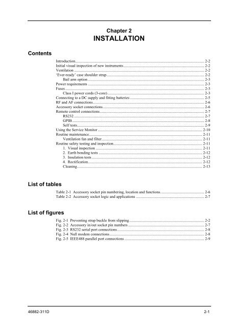
Contents<br />
List of tables<br />
List of figures<br />
Chapter 2<br />
INSTALLATION<br />
Introduction.................................................................................................................................... 2-2<br />
Initial visual inspection of new instruments................................................................................... 2-2<br />
Ventilation ..................................................................................................................................... 2-2<br />
‘Ever-ready’ case shoulder strap.................................................................................................... 2-2<br />
Bail arm option ....................................................................................................................... 2-3<br />
Power requirements ....................................................................................................................... 2-3<br />
Fuses .............................................................................................................................................. 2-3<br />
Class I power cords (3-core)................................................................................................... 2-3<br />
Connecting to a DC supply and fitting batteries ............................................................................ 2-5<br />
RF and AF connections.................................................................................................................. 2-6<br />
Accessory socket connections........................................................................................................ 2-6<br />
Remote control connections........................................................................................................... 2-7<br />
RS232 ..................................................................................................................................... 2-7<br />
GPIB....................................................................................................................................... 2-8<br />
Self tests.................................................................................................................................. 2-9<br />
Using the Service Monitor ........................................................................................................... 2-10<br />
Routine maintenance.................................................................................................................... 2-11<br />
Ventilation fan and filter....................................................................................................... 2-11<br />
Routine safety testing and inspection...........................................................................................2-11<br />
1. Visual inspection ............................................................................................................. 2-11<br />
2. Earth bonding tests .......................................................................................................... 2-12<br />
3. Insulation tests ................................................................................................................. 2-12<br />
4. Rectification..................................................................................................................... 2-12<br />
Cleaning................................................................................................................................ 2-13<br />
Table 2-1 Accessory socket pin numbering, location and functions............................................. 2-6<br />
Table 2-2 Accessory socket logic and applications ...................................................................... 2-7<br />
Fig. 2-1 Preventing strap buckle from slipping............................................................................. 2-2<br />
Fig. 2-2 Accessory in/out socket pin numbers .............................................................................. 2-7<br />
Fig. 2-3 RS232 serial port connections .........................................................................................2-8<br />
Fig. 2-4 Null modem connections................................................................................................. 2-8<br />
Fig. 2-5 IEEE488 parallel port connections .................................................................................. 2-9<br />
46882-311D 2-1


