Operating Manual for COMMUNICATIONS SERVICE MONITOR
Operating Manual for COMMUNICATIONS SERVICE MONITOR
Operating Manual for COMMUNICATIONS SERVICE MONITOR
Create successful ePaper yourself
Turn your PDF publications into a flip-book with our unique Google optimized e-Paper software.
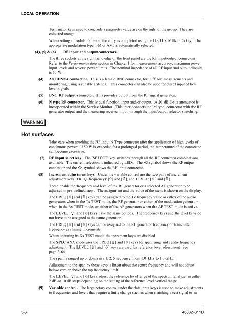
LOCAL OPERATION<br />
WARNING<br />
Terminator keys used to conclude a parameter value are on the right of the group. They are<br />
coloured orange.<br />
When setting a modulation level, the entry is completed using the Hz, kHz, MHz or % key. The<br />
appropriate modulation type, FM or AM, is automatically selected.<br />
(4), (5) & (6) RF input and output connectors.<br />
The three sockets at the right hand edge of the front panel are the RF input/output connectors.<br />
Refer to the Per<strong>for</strong>mance data section in Chapter 1 <strong>for</strong> measurement accuracy, maximum power<br />
input levels and reverse power limits. The nominal impedance of all RF input and output circuits<br />
is 50 W.<br />
(4) ANTENNA connection. This is a female BNC connector, <strong>for</strong> ’Off Air’ measurements and<br />
monitoring, using a suitable antenna. This connector can also be used <strong>for</strong> direct input of low<br />
level signals.<br />
(5) BNC RF output connector. This provides output from the RF signal generator.<br />
(6) N type RF connector. This is dual function, input and/or output. A 20 dB Delta attenuator is<br />
incorporated within the Service Monitor. This inter-connects the ’N type’ connector with the RF<br />
generator output and the measuring receiver input, through the input/output selector switching.<br />
Hot surfaces<br />
Take care when touching the RF Input N Type connector after the application of high levels of<br />
continuous power. If 50 W is exceeded <strong>for</strong> a prolonged period, the temperature of the connector<br />
can become excessive.<br />
(7) RF input select key. The [SELECT] key switches through all the RF connector combinations<br />
available. The current selection is indicated by LEDs. The � symbol shows the RF output<br />
connector and the � symbol shows the RF input connector.<br />
(8) Increment adjustment keys. Under the variable control are the two pairs of increment<br />
adjustment keys, FREQ (frequency): [�] and [�], and LEVEL: [�] and [�].<br />
These enable the frequency and level of the RF generator or a selected AF generator to be<br />
adjusted in pre-defined steps. The assignment and the value of the steps is shown on the display.<br />
The FREQ [�] and [�] keys can be assigned to the Tx frequency value or either of the audio<br />
generators when in the Tx TEST mode, the RF generator or either of the modulation generators<br />
when in the Rx TEST mode, or either of the AF generators when the AF TEST mode is active.<br />
The LEVEL [�] and [�] keys have the same options. The frequency keys and the level keys do<br />
not have to be assigned to the same generator.<br />
The FREQ [�] and [�] keys can be assigned to the RF generator frequency or transmitter<br />
frequency as channel increments.<br />
When operating in Dx TEST mode the increment keys are disabled.<br />
The SPEC ANA mode uses the FREQ [�] and [�] keys <strong>for</strong> span range and centre frequency<br />
adjustment. The LEVEL [�] and [�] keys are used <strong>for</strong> reference level adjustment. See<br />
page 3-64.<br />
The span is ranged up or down in a 1, 2, 5 sequence, from 1.0 kHz to 1.0 GHz.<br />
Adjustment to the span by these keys is linear about the centre frequency and will not adjust<br />
below zero or above the top frequency limit.<br />
The LEVEL [�] and [�] keys adjust the reference level range of the spectrum analyzer in either<br />
2 dB or 10 dB steps depending on the setting of the reference level vertical range.<br />
(9) Variable control. The large rotary control under the data input keys is used to make adjustments<br />
to frequencies and levels that require a finite change such as when matching a test signal to an<br />
3-6 46882-311D


