User Guide Corinex AV200 Powerline Ethernet Adapter
User Guide Corinex AV200 Powerline Ethernet Adapter
User Guide Corinex AV200 Powerline Ethernet Adapter

You also want an ePaper? Increase the reach of your titles
YUMPU automatically turns print PDFs into web optimized ePapers that Google loves.
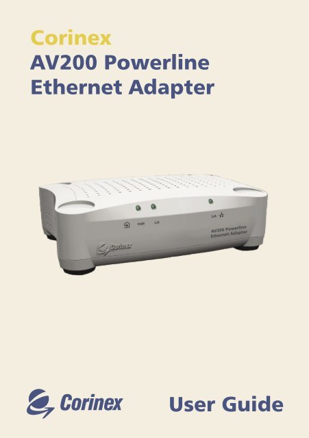
<strong>Corinex</strong><br />
<strong>AV200</strong> <strong>Powerline</strong><br />
<strong>Ethernet</strong> <strong>Adapter</strong><br />
<strong>User</strong> <strong>Guide</strong>
Copyright<br />
This document, as well as the software described in it, is furnished under license and<br />
may be used or copied only in accordance with the terms of the license. The content<br />
of this document is furnished for informational use only, it is subject to change without<br />
notice, and it does not represent a commitment on the part of <strong>Corinex</strong> Communications<br />
Corp.<br />
<strong>Corinex</strong> Communications Corp. assumes no responsibility or liability for any errors or<br />
inaccuracies that may appear in this document.<br />
It is our policy to enhance our products as new technologies, hardware components,<br />
software and firmware become available; therefore, the information contained in this<br />
document is subject to change without notice.<br />
Some features, functions, and operations described in this document may not be included<br />
and sold in certain countries due to government regulations or marketing policies.<br />
The use of the product or its features described in this document may be restricted or<br />
regulated by law in some countries. If you are unsure which restrictions or regulations<br />
apply, you should consult your regional <strong>Corinex</strong> office or the authorized reseller.<br />
Published by:<br />
<strong>Corinex</strong> Communications Corp.<br />
#670-789 West Pender Street<br />
Vancouver, B.C.<br />
Canada V6C 1H2<br />
Tel.: +1 604 692 0520<br />
Fax: +1 604 694 0061<br />
<strong>Corinex</strong> is a registered trademark of <strong>Corinex</strong> Communications Corp.<br />
Microsoft, MS-DOS, MS, Windows are either registered trademarks or trademarks of<br />
Microsoft Corporation in the U.S.A. and/or other countries.<br />
All products or company names mentioned herein may be the trademarks of their<br />
respective owners.<br />
Copyright (c) 2001-2005 by <strong>Corinex</strong> Communications Corp.<br />
NOTE: This equipment has been tested and found to comply with the limits for<br />
Class B information technology equipment. These limits are designed to provide<br />
reasonable protection against harmful interference in a residential installation.<br />
This equipment generates, uses and can radiate radio frequency energy and, if<br />
not installed and used in accordance with the instructions, may cause harmful<br />
interference to radio communications. However, there is no guarantee that interference<br />
will not occur in a particular installation. If this equipment does cause<br />
harmful interference, the end user is advised to take adequate measures.<br />
2005-02-08 ver. 1<br />
<strong>Corinex</strong> <strong>AV200</strong> <strong>Powerline</strong> <strong>Ethernet</strong> <strong>Adapter</strong><br />
1
CORINEX COMMUNICATIONS CORPORATION<br />
End <strong>User</strong> License Agreement<br />
This End <strong>User</strong> License Agreement (“EULA”) is a legal agreement between you and CORINEX<br />
COMMUNICATIONS CORPORATION (“CORINEX”) with regard to the copyrighted Software<br />
provided with this EULA.<br />
Use of any software and related documentation (“Software”) provided with a CORINEX hardware<br />
product, or made available to you by CORINEX via download or otherwise, in whatever form or media,<br />
will constitute your acceptance of these terms, unless separate terms are provided by the software<br />
supplier, in which case certain additional or different terms may apply. If you do not agree with the terms<br />
of this EULA, do not download, install, copy or use the Software.<br />
1. Licence Grant. CORINEX grants to you a personal, non-transferable and non-exclusive right to use<br />
the copy of the Software provided with this EULA. You agree you will not copy the Software except<br />
as necessary to use it on a single hardware product system. You agree that you may not copy the<br />
written materials accompanying the Software. Modifying, translating, renting, copying, transferring<br />
or assigning all or part of the Software, or any rights granted hereunder, to any other persons, and<br />
removing any proprietary notices, labels or marks from the Software is strictly prohibited. Furthermore,<br />
you hereby agree not to create derivative works based on the Software. You may permanently transfer<br />
all of your rights under this EULA, provided you retain no copies, you transfer all of the Software, and<br />
the recipient agrees to the terms of this EULA. If the Software is an upgrade, any transfer must include<br />
all prior versions of the Software.<br />
2. Copyright. The Software is licensed, not sold. You acknowledge that no title to the intellectual property<br />
in the Software is transferred to you. You further acknowledge that title and full ownership rights to<br />
the Software will remain the exclusive property of <strong>Corinex</strong> Communications Corporation and/or its<br />
suppliers, and you will not acquire any rights to the Software, except as expressly set forth above. All<br />
copies of the Software will contain the same proprietary notices as contained in or on the Software.<br />
3. Reverse Engineering. You agree that you will not attempt, and if you are a corporation, you will use<br />
your best efforts to prevent your employees and contractors from attempting to reverse compile,<br />
modify, translate or disassemble the Software in whole or in part. Any failure to comply with the above<br />
or any other terms and conditions contained herein will result in the automatic termination of this<br />
license and the reversion of the rights granted hereunder to CORINEX.<br />
4. Disclaimer of Warranty. The Software is provided “AS IS“ without warranty of any kind. CORINEX<br />
and its suppliers disclaim and make no express or implied warranties and specifically disclaim warranties<br />
of merchantability, fitness for a particular purpose and non-infringement of third-party rights. The<br />
entire risk as to the quality and performance of the Software is with you. Neither CORINEX nor its<br />
suppliers warrant that the functions contained in the Software will meet your requirements or that the<br />
operation of the Software will be uninterrupted or error-free.<br />
5. Limitation of Liability. <strong>Corinex</strong>’s entire liability and your exclusive remedy under this EULA shall not<br />
exceed the price paid for the Software, if any. In no event shall CORINEX or its suppliers be liable to<br />
you for any consequential, special, incidental or indirect damages of any kind arising out of the use or<br />
inability to use the software, even if CORINEX or its supplier has been advised of the possibility of such<br />
damages, or any claim by a third party.<br />
6. Applicable Laws. This EULA will be governed by the laws of Canada, excluding its conflict of law<br />
provisions.<br />
<strong>Corinex</strong> <strong>AV200</strong> <strong>Powerline</strong> <strong>Ethernet</strong> <strong>Adapter</strong><br />
2
End <strong>User</strong> License Agreement<br />
7. Export Laws. This EULA involves products and/or technical data that may be controlled under any<br />
applicable export control laws, and regulation, and may be subject to any approval required under such<br />
laws and regulations.<br />
8. Precedence. Except as set out above, where separate terms are provided by the software supplier,<br />
then, subject to this EULA, those terms also apply and prevail, to the extent of any inconsistency with<br />
this EULA.<br />
<strong>Corinex</strong> <strong>AV200</strong> <strong>Powerline</strong> <strong>Ethernet</strong> <strong>Adapter</strong><br />
3
Contents<br />
Contents<br />
Copyright .......................................................................................... 1<br />
End <strong>User</strong> License Agreement .............................................................. 2<br />
1. Introduction ..................................................................................... 5<br />
1.1 Overview ........................................................................................... 5<br />
1.2 About this manual ............................................................................ 5<br />
2. Installation <strong>Guide</strong> .............................................................................. 6<br />
2.1 What this Package Contains ............................................................... 6<br />
2.2 System Requirements ........................................................................ 6<br />
2.3 Front Panel Description ..................................................................... 6<br />
2.4 Rear Panel Description ....................................................................... 7<br />
2.6 Installing the <strong>AV200</strong> <strong>Powerline</strong> <strong>Adapter</strong> ............................................ 8<br />
2.7 Testing the Setup .............................................................................. 8<br />
3. Web Configuration ............................................................................ 9<br />
3.1 Authentication Page .......................................................................... 9<br />
3.2 Main Page ....................................................................................... 10<br />
3.3 Further Information Page................................................................. 11<br />
3.4 Change Configuration Page ............................................................ 12<br />
3.5 Firmware Update Page ................................................................... 23<br />
4. In-Home AV Network Topology .................................................. 24<br />
4.1 Introduction ................................................................................... 24<br />
4.2 Network Scenarios ......................................................................... 24<br />
5. Network Configuration ................................................................... 28<br />
5.1 Setting an IP Address in your computer .......................................... 28<br />
5.2 Improving Network Performance ................................................... 34<br />
5.3 Checking Network Performance .................................................... 35<br />
5.4 Using PLC Filtres ............................................................................. 35<br />
6. Troubleshooting <strong>Guide</strong> .................................................................. 37<br />
<strong>Corinex</strong> <strong>AV200</strong> <strong>Powerline</strong> <strong>Ethernet</strong> <strong>Adapter</strong><br />
4
1 Introduction<br />
1.1 Overview<br />
Introduction<br />
The <strong>Corinex</strong> <strong>AV200</strong> <strong>Powerline</strong> <strong>Adapter</strong> is a network interface adapter which uses the<br />
electric power lines already in your home or office as a medium for communication.<br />
After successful installation, the <strong>AV200</strong> <strong>Powerline</strong> network behaves like a traditional<br />
LAN for computers. The <strong>Corinex</strong> <strong>AV200</strong> <strong>Powerline</strong> <strong>Adapter</strong> supports up to 200 Mbps<br />
network speed.<br />
The advantage of our product is that it keeps network maintenance costs low and<br />
eliminates usage barriers, while requiring no additional wiring. It is highly integrated,<br />
and requires no external electronic components.<br />
The <strong>Corinex</strong> <strong>AV200</strong> <strong>Powerline</strong> <strong>Adapter</strong>:<br />
• Enables users to connect individual PCs or other devices with <strong>Ethernet</strong><br />
communications links into a local area network through existing electric<br />
power lines (<strong>Powerline</strong>)<br />
• Enables PC file and application sharing<br />
• Enables peripheral and printer sharing through the <strong>Powerline</strong> network<br />
• Enables shared broadband Internet access<br />
• Enables sharing of bandwidth for multimedia payloads, including voice, data,<br />
audio and video<br />
• Eliminates the need for long network cables throughout your home or office<br />
• A real, cost-effective, and reliable solution for high-speed communications in<br />
any home or small office<br />
1.2 About this Manual<br />
This <strong>User</strong> <strong>Guide</strong> includes everything you need to know to help you successfully<br />
install the <strong>Corinex</strong> <strong>AV200</strong> <strong>Powerline</strong> <strong>Adapter</strong> and meet your networking needs. With<br />
the information in this manual, you should be able to:<br />
• Analyze your network efficiency<br />
• Plan the configuration of your <strong>Corinex</strong> <strong>AV200</strong> <strong>Powerline</strong> <strong>Adapter</strong><br />
• Install and configure your <strong>Corinex</strong> <strong>AV200</strong> <strong>Powerline</strong> <strong>Adapter</strong> according to<br />
your plan<br />
• Verify and optimize the performance of your <strong>Corinex</strong> <strong>AV200</strong> <strong>Powerline</strong><br />
<strong>Adapter</strong><br />
<strong>Corinex</strong> <strong>AV200</strong> <strong>Powerline</strong> <strong>Ethernet</strong> <strong>Adapter</strong><br />
5
2 Installation <strong>Guide</strong><br />
2.1 What this Package Contains<br />
Installation <strong>Guide</strong><br />
When you receive your <strong>Corinex</strong> <strong>AV200</strong> <strong>Powerline</strong> <strong>Adapter</strong>, check to be sure that your<br />
package contains:<br />
• <strong>Corinex</strong> <strong>AV200</strong> <strong>Powerline</strong> <strong>Adapter</strong><br />
• Power cable<br />
• Straight-forward <strong>Ethernet</strong> cable<br />
• Printed Quick Start <strong>Guide</strong><br />
• CD with documentation<br />
We are constantly innovating our products. For the latest hardware/software<br />
changes, downloads, and additional information on your device, please visit<br />
www.corinex.com.<br />
We also advise you to visit our <strong>Corinex</strong> Authorized <strong>Powerline</strong> Partners Program<br />
web page http://cappp.corinex.com/, where you can find valuable information<br />
about complex applications and installations, as well as partners in your area who<br />
can provide installation services.<br />
2.2 System Requirements<br />
• IBM compatible PC or a Macintosh<br />
• One available 10/100 Mbps <strong>Ethernet</strong> port<br />
• Windows 98/ME/2000/NT/XP, Mac OS X or Linux operating system<br />
• Javascript compatible web browser for configuration (Netscape, Internet<br />
Explorer, Opera…)<br />
2.3 Front Panel Description<br />
LED Definitions<br />
(LEDs from left to right)<br />
<strong>Corinex</strong> <strong>AV200</strong> <strong>Powerline</strong> <strong>Ethernet</strong> <strong>Adapter</strong><br />
6
1. POWER Green On: Power on<br />
Off: Power off<br />
2. PLC Green On: <strong>Powerline</strong> activity<br />
Off : No <strong>Powerline</strong> activity<br />
Blinking : Receiving/Transmitting data<br />
3. ETHERNET Green On: Link on LAN<br />
Off: No link on LAN<br />
Blinking: receiving/transmitting data<br />
2.4 Rear Panel Description<br />
Connector Definitions<br />
(Connectors from left to right)<br />
1. LAN: 1x RJ-45 LAN10/100 <strong>Ethernet</strong> port<br />
2. Power cord: Power supply & <strong>Powerline</strong> connector<br />
Installation <strong>Guide</strong><br />
Standards Compliance IEEE 802.3u<br />
Speed Up to 200 Mbps on physical layer<br />
AC Plug Type US, EU, UK and AUS<br />
LED Status Lights Power, PLC Link/Activity, <strong>Ethernet</strong> Link<br />
Interface 10/100BaseT Fast <strong>Ethernet</strong>, <strong>Powerline</strong><br />
Frequency Range used 2 – 34 MHz<br />
Power Input 85 to 265 V AC, 50/60 Hz<br />
Dimensions 148 mm L x 106 mm W x 47 mm H<br />
Transmitted Power spectral density -56 dBm/Hz<br />
Power Consumption 5W<br />
Safety & EMI UL/EN 60950, FCC Part 15, EN 55022<br />
EMC limits<br />
<strong>Corinex</strong> <strong>AV200</strong> <strong>Powerline</strong> <strong>Ethernet</strong> <strong>Adapter</strong><br />
7
2.6 Installing the <strong>AV200</strong> <strong>Powerline</strong> <strong>Adapter</strong><br />
Installation <strong>Guide</strong><br />
To connect the <strong>Corinex</strong> <strong>AV200</strong> <strong>Powerline</strong> <strong>Adapter</strong> to your computer, follow the steps<br />
listed below.<br />
1. Connect the supplied <strong>Ethernet</strong> cable to the LAN port on the adapter and to<br />
an <strong>Ethernet</strong> port on your computer.<br />
2. Connect the power cable to the <strong>Powerline</strong> port on the adapter and the other<br />
end into any AC electrical outlet.<br />
Note: Please use a straight-forward <strong>Ethernet</strong> cable for connection of the<br />
<strong>AV200</strong> <strong>Powerline</strong> <strong>Adapter</strong> to your computer. If you are connecting the <strong>AV200</strong><br />
<strong>Powerline</strong> <strong>Adapter</strong> to a modem or switch, please use a crossover cable.<br />
2.7 Testing the Setup<br />
To verify that your equipment is connected and working correctly, use the standard<br />
Ping utility. In Windows, click on menu Start -> Run, then write the command<br />
ping IPADDRESS -t, where IPADDRESS is the IP address of the computer to<br />
which the <strong>AV200</strong> <strong>Powerline</strong> <strong>Adapter</strong> is connected, e.g. ping 192.168.4.1 -t (this<br />
process can be interrupted by pressing CTRL+C).<br />
1. Ping the IP address of the computer to which the <strong>AV200</strong> <strong>Powerline</strong> <strong>Adapter</strong><br />
is connected. If this fails, there is a problem with the <strong>Ethernet</strong> network card<br />
or with the TCP/IP protocol.<br />
2. Repeat the same process with the other computers on your <strong>AV200</strong> <strong>Powerline</strong><br />
network.<br />
3. If all the computers can ping themselves, try pinging another computer on<br />
your <strong>AV200</strong> <strong>Powerline</strong> network. If this fails, then there is a problem with the<br />
connection across your <strong>AV200</strong> <strong>Powerline</strong> network or with the configuration<br />
of the <strong>AV200</strong> <strong>Powerline</strong> <strong>Adapter</strong>s. Check the connection to the outlet, or<br />
try a different outlet. Verify the configuration of the <strong>AV200</strong> <strong>Powerline</strong><br />
<strong>Adapter</strong>s, especially the network number, as only adapters in the same<br />
network can see each other. Please see chapter 3 for details on<br />
configuration.<br />
If you experience any problems with your setup, try unplugging the <strong>AV200</strong> <strong>Powerline</strong><br />
<strong>Adapter</strong> and restarting the computer, as this sometimes fixes the problem. If the<br />
problem persists, please refer to the troubleshooting guide at the end of this<br />
manual.<br />
<strong>Corinex</strong> <strong>AV200</strong> <strong>Powerline</strong> <strong>Ethernet</strong> <strong>Adapter</strong><br />
8
3 Web Configuration<br />
Web Configuration<br />
In order to access the web configuration pages, it is necessary to know the adapter’s<br />
IP address and to be connected to it (e.g. through an <strong>Ethernet</strong> cable). <strong>Adapter</strong>s that<br />
have not previously been configured have the IP address 10.10.1.69. Open a web<br />
browser (Microsoft Internet Explorer v6.0, Mozilla v1.7.2 and Mozilla Firefox v1.0<br />
have been verified for use with these products.), and type the IP address in the<br />
address bar – the URL should be http://10.10.1.69/ unless you are not setting it up<br />
for the first time, and you have previously changed it to something else.<br />
Changing the default IP address, 10.10.1.69, is required to allow access to an<br />
adapter when two or more units are active on the same network. The IP address<br />
is a device’s unique identifier on a network, so the adapters would not be able<br />
to tell each other apart if they had the same identity, just as a postman wouldn’t<br />
know which house to deliver to, if two neighbors in a large city had the same street<br />
number. Follow the steps below to configure a new IP address for each adapter:<br />
1. In your computer’s network settings, enter an address in the range 10.10.<br />
X.X and the netmask 255.255.0.0. This is necessary in order to be compatible<br />
with the adapter’s default settings. For details on how to set up an IP address<br />
in your computer, please see chapter 5.<br />
2. Plug in your <strong>AV200</strong> <strong>Powerline</strong> <strong>Adapter</strong> and connect it to the PC via supplied<br />
<strong>Ethernet</strong> cable.<br />
3. Open the Web browser and type the following URL: http://10.10.1.69. You<br />
will get to the configuration web interface of the <strong>AV200</strong> <strong>Powerline</strong> <strong>Adapter</strong>.<br />
3.1 Authentication Page<br />
If the configuration password is enabled, you’ll need to login before you can access<br />
the web pages where you make changes to the network. Therefore, you will first<br />
be taken to an Authentication page, where you will need to enter either the<br />
configuration password – to access these web pages or a factory reset password<br />
– in order to set the configuration to a default value. The embedded web server<br />
has an authentication timeout of 5 minutes; i.e. if no web pages are loaded within 5<br />
minutes, the login expires and you will need to login again.<br />
Note: The default password for accessing the configuration is “paterna”.<br />
The default password for resetting the adapter into default settings is<br />
“betera”.<br />
<strong>Corinex</strong> <strong>AV200</strong> <strong>Powerline</strong> <strong>Ethernet</strong> <strong>Adapter</strong><br />
9
Web Configuration<br />
Note: If password protection is disabled, you will be taken straight to the<br />
Main page instead of the Authentication page.<br />
3.2 Main Page<br />
This is the first page you will see after logging in, or simply the first page, if the configuration<br />
password is disabled. It shows basic status information about the adapter,<br />
available <strong>Powerline</strong> connections, MAC and IP addresses, MAC type, etc.<br />
Selecting Further information will load the Further Information page (see section<br />
3.3). Selecting Change configuration will load the Change Configuration page (see<br />
section 3.4).<br />
<strong>Corinex</strong> <strong>AV200</strong> <strong>Powerline</strong> <strong>Ethernet</strong> <strong>Adapter</strong><br />
10
3.3 Further Information Page<br />
Web Configuration<br />
This page shows more detailed information about the modem, such as the uptime,<br />
firmware version or detailed information about the settings of the modem.<br />
You can return to the main page by clicking at Return to main page.<br />
<strong>Corinex</strong> <strong>AV200</strong> <strong>Powerline</strong> <strong>Ethernet</strong> <strong>Adapter</strong><br />
11
3.4 Change Configuration Page<br />
3.4.1 Overview<br />
Web Configuration<br />
The configuration page allows you to change some basic parameters on the adapter.<br />
Any parameter changed here will be stored in the adapter‘s permanent memory, and<br />
loaded and configured automatically after the next system boot. Any changes will<br />
take effect immediately after bootup, with the exception of Network Configuration<br />
settings (these require a reset of the adapter).<br />
Notes:<br />
• A different IP must be set for each adapter within a single network. An adapter’s<br />
IP does not need to be in the same range as the PCs communicating with the<br />
adapters. But to access the configuration page, a PC must have the same address<br />
range as the adapter (10.10.X.X and netmask 255.255.0.0 in the default state).<br />
• The adapter’s netmask can also be changed, for example to a type C<br />
(255.255.255.0) if necessary. This is a more advanced option, which you may<br />
ignore if you’re not familiar with it.<br />
<strong>Corinex</strong> <strong>AV200</strong> <strong>Powerline</strong> <strong>Ethernet</strong> <strong>Adapter</strong><br />
12
Web Configuration<br />
• If the adapter will be accessed through a router (for example in a large office<br />
network), the gateway IP needs to be configured. Otherwise, it can be ignored.<br />
CHANGING AN ADAPTER‘S IP TAKES EFFECT ONLY AFTER A RESTART OR<br />
REBOOT. YOU MAY WANT TO PLACE A LABEL ON EACH ADAPTER WITH ITS<br />
IP ADDRESS, SO YOU DON’T LOSE THE ABILITY TO ACCESS IT.<br />
If you change the IP Address and forget it, there is no way to<br />
reset it to default. This may imply sending the unit to <strong>Corinex</strong><br />
for reprogramming.<br />
3.4.2 MAC Configuration<br />
The following parameters relate to the network topology. The current firmware<br />
version (Spirit 1.2.1 at the time of this publication) supports only one topology: In-<br />
Home AV. In this In-Home AV topology, two different node types can be configured,<br />
so that a node can be either an Automatic EP/AP (End Point or Access Point,<br />
depending on the other nodes in the network) or a Fixed AP (configured Access<br />
Point). Section 4 (In-Home AV Network Topology) contains more information about<br />
the available network topologies.<br />
If you want to configure the adapter to act as an automatic EP/AP, please select EP<br />
from the list. If you want the adapter to behave as a master, select Fixed AP from<br />
the list. In either case, click OK to confirm your selection.<br />
Note: Fixed AP is available only when the adapter is configured with a<br />
non-empty Network Identifier (please read below for details on Network<br />
Identifiers).<br />
<strong>Corinex</strong> <strong>AV200</strong> <strong>Powerline</strong> <strong>Ethernet</strong> <strong>Adapter</strong><br />
13
Web Configuration<br />
The <strong>AV200</strong> technology supports multiple networks on a single electrical circuit. The<br />
networks are differentiated by Network Identifiers, which can be set in the MAC<br />
section. The Network Identifier is a character string (Network Identifier field) which<br />
simply acts as a name for the network. It must be the same value for all adapters<br />
on the same network. <strong>Adapter</strong>s with different Network Identifiers are not able to<br />
communicate with each other.<br />
Note: Please refer to section 4.2 for more information about the network<br />
types and their Network Identifiers.<br />
In case of a null string (i.e. the Network Identifier field left blank), the default<br />
publicly available network is configured, and the adapter can communicate with any<br />
other adapter which also has a blank Network Identifier field. Otherwise, a private<br />
network is configured.<br />
The following picture shows an example of two <strong>AV200</strong> networks with different<br />
Network Identifiers.<br />
Data transmission between adapters (modems, in the picture) is encrypted with<br />
a Triple-DES algorithm. The Encryption Key can be configured from a character<br />
string (Encryption Key field), which is actually a passphrase. The three 56-bit keys<br />
for Triple-DES encryption are obtained from this passphrase by means of a hash<br />
function. Entering a null string (leaving it blank) disables the encryption. After<br />
entering a passphrase, click OK to confirm your choice.<br />
Note: The encryption will be enabled only if a non-empty Network Identifier<br />
is set.<br />
<strong>Corinex</strong> <strong>AV200</strong> <strong>Powerline</strong> <strong>Ethernet</strong> <strong>Adapter</strong><br />
14
3.4.3 Network Configuration<br />
Web Configuration<br />
Your <strong>Corinex</strong> <strong>AV200</strong> <strong>Powerline</strong> <strong>Adapter</strong> can be configured to use either DHCP<br />
(automatic IP address assignment), or a fixed IP.<br />
The following parameters are used by the fixed IP configuration. In order to use the<br />
adapter in conjunction with other equipment within an In-Home AV network, it is<br />
necessary to define a valid and unique IP address in the network, as well as a proper<br />
subnet mask and gateway address. These parameters will be stored in the adapter<br />
and implemented following the next system boot.<br />
After changing any of these parameters, click OK to save your changes.<br />
Note: Any change in the Network Settings requires a subsequent reboot of<br />
the adapter.<br />
3.4.4 PHY Configuration<br />
By default, the adapters transmit using a frequency anywhere from 2 to 32 MHz, and<br />
when an access network is detected, the adapters transmit using a frequency from<br />
13.3 to 33.3 MHz, in order to operate without interfering with each other. This<br />
mode change is done automatically and cannot be configured by the user. It is only<br />
possible to enable or disable this „notches“ function. The notches pre-defined in the<br />
adapter correspond to the IARU band plan for each world region. If the adapter is<br />
running in an environment where it can cause interference to a HAM radio receiver,<br />
it is recommended to enable notches, in order to block the <strong>Powerline</strong> signal from<br />
the frequency bands used by HAM radio.<br />
<strong>Corinex</strong> <strong>AV200</strong> <strong>Powerline</strong> <strong>Ethernet</strong> <strong>Adapter</strong><br />
15
3.4.5 Multicast Configuration<br />
Web Configuration<br />
In order to optimize multicast traffic (video streams, etc.) between <strong>AV200</strong> <strong>Powerline</strong><br />
adapters, you can specify which adapters you want to receive the traffic. Others<br />
will then not be able to receive the multicast communication, and therefore the<br />
bandwidth will be used only for transmission to the intended recipients, making your<br />
broadcast, and overall network, more efficient.<br />
This form shows the list of multicast bindings, where multicast IP addresses are<br />
assigned to a unicast (stream source) MAC address. This list can be saved to the<br />
adapter (Save in NVRAM). Moreover, you can remove bindings by checking their<br />
Remove checkboxes and clicking OK. Add a new binding to the list by entering the<br />
multicast IP address, in decimal (ddd.ddd.ddd.ddd) format, and the unicast MAC<br />
address, in hexadecimal (XXXXXXXXXXXX) format, in the appropriate fields,<br />
and clicking OK.<br />
3.4.6 VLAN Configuration<br />
When <strong>AV200</strong> <strong>Powerline</strong> adapters are used for ADSL extension, it is important for the<br />
operator to be able to distinguish the type of traffic that each adapter is generating.<br />
This is usually done by means of VLAN tagging. The <strong>AV200</strong> technology includes the<br />
ability to tag all traffic that enters the <strong>Powerline</strong> network through each adapter’s<br />
<strong>Ethernet</strong> interface. It is only tagging - there is no VLAN filtering on an <strong>AV200</strong><br />
<strong>Powerline</strong> network.<br />
The parameters for VLAN configuration can be set in the form displayed below.<br />
First the Spirit VLAN can be enabled or disabled (Spirit VLAN Configuration select<br />
box). If enabled, the VLAN tag (Spirit VLAN Tag field) and priority (Spirit VLAN Priority<br />
field) can then also be configured.<br />
<strong>Corinex</strong> <strong>AV200</strong> <strong>Powerline</strong> <strong>Ethernet</strong> <strong>Adapter</strong><br />
16
3.4.7 Priority Configuration<br />
Web Configuration<br />
Several options are available in this form. The first, and easiest to understand and<br />
use, is the Default Priority value. Output traffic generated by adapters with higher<br />
default priority will have preference in the network. The rest of the parameters let<br />
you configure two Class of Service criteria (Criterion 1 and Criterion 2 select<br />
boxes).<br />
If you select None, 8021p or TOS, custom parameters are hidden, leaving a predefined<br />
setting in place.<br />
If you select Custom on the other hand, custom parameters are shown as below<br />
and can then be configured.<br />
<strong>Corinex</strong> <strong>AV200</strong> <strong>Powerline</strong> <strong>Ethernet</strong> <strong>Adapter</strong><br />
17
Web Configuration<br />
When several traffic flows are sharing the same network, you sometimes need to<br />
establish several levels of priority to guarantee that bandwidth-sensitive applications<br />
such as video or telephony continue to work smoothly under network congestion.<br />
The traffic classifier is a packet inspector that is able to recognize several patterns<br />
in an <strong>Ethernet</strong> frame, and assign a different priority to each of them. To ensure that<br />
the classification is done correctly, there is a trigger mechanism before the actual<br />
classification. The trigger mechanism is also based on pattern recognition of a given<br />
location in each <strong>Ethernet</strong> packet. The following picture depicts the packet classification<br />
mechanism.<br />
There is one offset, one bitmask and pattern for the trigger condition. The trigger<br />
condition is used to make sure that the <strong>Ethernet</strong> frame contains, for example, an IP<br />
frame. To check this condition, the offset would need to be set to 16 and the bitmask<br />
to 0xFFFF. If the resulting pattern is 0x0800, then the <strong>Ethernet</strong> frame contains<br />
an IP packet and the classification can be made to a known field.<br />
There is another offset and bitmask for the classification condition. The resulting<br />
value is compared with a set of patterns. If the value matches a given pattern, the<br />
packet will be classified with the specified priority. If the value does not match any of<br />
the patterns, it will get a default priority.<br />
There is a set of pre-defined criteria that allow classifying traffic based on the 802.1p<br />
field of the <strong>Ethernet</strong> packet or the TOS field of the IP packet.<br />
<strong>Corinex</strong> <strong>AV200</strong> <strong>Powerline</strong> <strong>Ethernet</strong> <strong>Adapter</strong><br />
18
3.4.8 Security Configuration<br />
Web Configuration<br />
The web application allows you to change the configuration password by typing a<br />
new one in the specified fields (You must confirm your password by re-typing it in<br />
the second field). If both fields are left empty, the configuration password will be<br />
disabled (the message ‘No password installed’ will be shown in the security configuration<br />
form). Consequently, the web configuration authentication will be disabled<br />
too. The authentication can be enabled again by setting a password.<br />
If you want to restore the adapter‘s default settings, you can invoke a factory reset.<br />
In order to do this, you have to enter the password „betera“ in the appropriate<br />
field and click OK. The adapter will reboot with the following configuration:<br />
- IP address = 10.10.1.69<br />
- Configuration interface password = paterna<br />
- Factory reset password = betera<br />
- Device type is Automatic EP/AP<br />
- Network Identifier is blank<br />
- No encryption and no VLAN settings<br />
3.4.9 Hardware Reset<br />
Clicking on this button will reset (or reboot) your adapter. The configuration will<br />
remain the same, and any changes made in the Network Configuration section will<br />
be applied. This means that if you’ve changed the IP address, the adapter will reboot<br />
with that new address.<br />
<strong>Corinex</strong> <strong>AV200</strong> <strong>Powerline</strong> <strong>Ethernet</strong> <strong>Adapter</strong><br />
19
3.4.10 Flash Upgrade<br />
Web Configuration<br />
The firmware, the loader and the factory settings (default factory configuration) are<br />
stored in Flash memory. To upgrade them, first select the Flash section to update<br />
(Firmware, Loader or Factory Settings) and the protocol (FTP or TFTP). Then<br />
type the IP address of the FTP or TFTP server (Server IP Address field). In the<br />
case of FTP, type the user name (FTP <strong>User</strong>) and password (FTP Password). Then,<br />
whether using FTP or TFTP, type the file name of the firmware disk image (File<br />
Name). And finally, press OK.<br />
3.4.11 Firmware upgrade using a TFTP Server<br />
To upgrade the firmware of the modem using TFTP, a TFTP server must be running<br />
on a computer. We recommend a freeware tool called TFTPD32. This tool can be<br />
downloaded at the following address: http://tftpd32.jounin.net/. The firmware<br />
image is provided by <strong>Corinex</strong>.<br />
Follow the steps below to upgrade the firmware of a modem:<br />
1. Execute TFTPD32. This application has the GUI shown in the picture below<br />
<strong>Corinex</strong> <strong>AV200</strong> <strong>Powerline</strong> <strong>Ethernet</strong> <strong>Adapter</strong><br />
20
Web Configuration<br />
2. Place the image file in the directory specified in Current Directory or change it<br />
to point to the place where the image is stored.<br />
3. Open the Web browser and enter the IP of the modem that to be upgraded.<br />
4. When the page comes up, click on Change configuration.<br />
5. In the Firmware Update window, select TFTP and enter the IP of the TFTP<br />
server and the name of the image file, as shown in the next picture.<br />
6. Click OK to start the process. Progress information is shown on the Web page<br />
every 30 seconds.<br />
7. The modem will first download the file and then calculate the CRC.<br />
8. If the CRC is correct, the Hardware Reset button will be highlighted. The<br />
modem must be reset for the new firmware to start running.<br />
<strong>Corinex</strong> <strong>AV200</strong> <strong>Powerline</strong> <strong>Ethernet</strong> <strong>Adapter</strong><br />
21
3.4.12 Configuring Video Applications<br />
Web Configuration<br />
In the case of a network where real-time traffic must coexist with massive data<br />
transfers, the service classifier must be used to prioritize the bandwidth-sensitive<br />
traffic above the other types of traffic.<br />
As an example, consider the network shown below.<br />
The node connected to the ADSL modem is the access point. Data and video are<br />
delivered through ADSL. The access point has to prioritize UDP video over data to<br />
avoid a jittery image when there is a heavy data download.<br />
First of all, the Criterion field must be set to Custom, in order to create one’s own<br />
rules to classify the traffic.<br />
To prioritize UDP traffic, first the <strong>Ethernet</strong> packets containing IP packets have to be<br />
detected. This requires detecting the pattern 0x0800 at offset 16. Because the field<br />
to inspect is two bytes, the bitmask must also cover the same space. Therefore,<br />
0xFFFF is used as bitmask. These values are introduced in the fields Custom Criterion<br />
Offset, Custom Criterion Pattern and Custom Criterion Bitmask.<br />
<strong>Corinex</strong> <strong>AV200</strong> <strong>Powerline</strong> <strong>Ethernet</strong> <strong>Adapter</strong><br />
22
Web Configuration<br />
Once the trigger condition is entered, the classification rules must be specified.<br />
Only the fields that are actually changed will take effect. The rest will be ignored.<br />
IP packets have a one-byte field at offset 27 that indicates the Protocol Type.<br />
UDP protocol is pattern 0x11. Because the field to inspect is only one byte, the<br />
bitmask is also one byte. The values are entered in the first available rule (1) as Class<br />
Pattern 1 and Class Priority 1.<br />
The rest of the traffic (FTP, Web browsing, etc.) will receive default priority 2. On<br />
the other side of the network, the modem connected to the computer will also<br />
classify outgoing data traffic with default priority 2 because no rule has been programmed.<br />
Note: While the offset value is assumed to be decimal, the patterns and the<br />
bitmasks are in hexadecimal format by default.<br />
3.5 Firmware Update Page<br />
This page appears when a firmware update is requested from the Change<br />
Configuration page, and it shows the status of the current firmware update. The<br />
Firmware Update page is reloaded automatically every 30 seconds. When the<br />
status line shows Ready: finished correctly, the adapter can be restarted, and the<br />
new firmware will be loaded.<br />
If the update process fails, an error message will be shown. In this situation, the<br />
adapter can be reset without any risk, but the old firmware will still be present on<br />
the adapter.<br />
<strong>Corinex</strong> <strong>AV200</strong> <strong>Powerline</strong> <strong>Ethernet</strong> <strong>Adapter</strong><br />
23
4 In-Home AV Network Topology<br />
4.1 Introduction<br />
In-Home AV Network Topology<br />
An In-Home AV network is made of an access point (AP) node and several end<br />
points (EPs). One and only one access point (AP) can be in an In-Home AV network.<br />
However, it is possible that more than one In-Home AV network can coexist<br />
together, each of them with its own AP, because each of them is isolated from the<br />
others by means of a different network identifier. A modem can be configured as a<br />
Fixed AP (i.e. it always will be an AP) or an automatic EP/AP. In case of automatic<br />
configuration, the In-Home AV protocol will decide dynamically if the node becomes<br />
an EP or an AP. It means, that in a network where no Access Point (AP) has been<br />
defined, at least one of the End Points (EPs) will redefine itself as an automatic AP.<br />
Note: It is not necessary to have full connectivity between all of the nodes<br />
in one network. The network topology will be configured automatically,<br />
allowing for the use of repeaters if the connectivity between two nodes<br />
falters.<br />
The necessary steps to set a basic In-Home AV network are, for each node, as<br />
follows:<br />
- Set its IP address. It should be a unique IP address (e.g. private address like<br />
10.10.1.).<br />
- Select the spectral configuration (notches enabled or disabled).<br />
- Set the Network Identifier. It should be the same value for all nodes in the<br />
network.<br />
- Configure the Encryption Key. It should also be the same value for all nodes in<br />
the network.<br />
- It is not necessary to configure the In-Home AV MAC, since there is only one<br />
available network topology in current firmware version. To configure a Fixed<br />
AP is optional.<br />
4.2 Network Scenarios<br />
In this section the user is presented with a few network scenarios, explaining the<br />
application and necessary configuration.<br />
There are two types of an In-Home AV network.<br />
<strong>Corinex</strong> <strong>AV200</strong> <strong>Powerline</strong> <strong>Ethernet</strong> <strong>Adapter</strong><br />
24
In-Home AV Network Topology<br />
• Public Network - This is the default configuration of an In-Home network. If<br />
the user does not want to configure its network, the network configuration<br />
protocol will configure all nodes automatically. By default, all nodes are EPs<br />
and have a public network ID. If the protocol does not detect an AP in the<br />
channel, it will select an EP as automatic AP. All EPs will connect directly to<br />
the automatic AP if they have direct visibility, or to an EP that will act as a<br />
repeater. Then the network will be established.<br />
• Private Network - To configure a private network (to ensure data privacy),<br />
a network ID must be assigned to all nodes of the network using the<br />
configuration tool. It is recommended to configure a node as a fixed AP (for<br />
example the node with the video server or Internet access). If the fixed AP is<br />
turned off or it is not defined by the user, the network configuration protocol<br />
will select an EP to be transformed into an AP (automatic) to configure the<br />
network.<br />
4.2.1 Single-Network Scenarios<br />
The following two sections show examples of a single In-Home AV network.<br />
4.2.1.1 Local Area Network using two <strong>AV200</strong> powerline adapters<br />
The picture below shows a simple PLC (<strong>Powerline</strong>) network where two adapters<br />
are used to make a local area connection available in all outlets of the house. This is<br />
the simplest case, where no QoS (Quality of Service) configuration is required.<br />
<strong>Corinex</strong> <strong>AV200</strong> <strong>Powerline</strong> <strong>Ethernet</strong> <strong>Adapter</strong><br />
25
In-Home AV Network Topology<br />
4.2.1.2 Extending the internet connection to an <strong>AV200</strong> powerline<br />
network<br />
The next picture shows a more advanced PLC (<strong>Powerline</strong>) network with three<br />
<strong>Corinex</strong> <strong>AV200</strong> <strong>Powerline</strong> <strong>Adapter</strong>s. This is a common network configuration, where<br />
Internet access and digital video are delivered through the same ADSL line. This<br />
configuration requires some QoS (Quality of Service) settings to guarantee video<br />
quality when the network is carrying large amounts of data from the Internet<br />
connection.<br />
Note: Any of these two basic scenarios can be enlarged, adding more adapters,<br />
computers and set-top boxes.<br />
4.2.2 Multi-Network Scenarios<br />
A multi-network scenario occurs whenever there are two or more nodes from<br />
different In-Home AV networks (different network IDs) that have direct visibility.<br />
In this case, a coexistence mechanism that allows a secure form of communication<br />
without interference from nodes from different networks is included.<br />
<strong>Corinex</strong> <strong>AV200</strong> <strong>Powerline</strong> <strong>Ethernet</strong> <strong>Adapter</strong><br />
26
In-Home AV Network Topology<br />
In multi-network scenarios, such as the one depicted in the picture above, there<br />
is a new entity, called the QoS controller. The QoS controller’s role is to assign<br />
channel access to the different networks. The QoS controller acts at the same time<br />
as the AP of one of the networks. In the presence of several In-Home networks, the<br />
coexistence protocol automatically selects one of the APs as the QoS controller.<br />
4.2.2.1 Two networks with no visibility<br />
If two In-Home AV networks are configured, with no direct visibility between any of<br />
the nodes belonging to different networks, then these two networks will behave as<br />
two independent networks. Both APs will act as QoS controllers.<br />
4.2.2.2 Two networks with direct visibility<br />
Different networks are defined by different network IDs.<br />
If two In-Home AV networks are configured as public networks, the coexistence<br />
protocol will act as if there were only one network. The network ID is transmitted<br />
by every node to communicate the existence of its network. If a node with a network<br />
ID A receives a network ID B, then it knows that there are at least two networks<br />
sharing the channel.<br />
For example, one In-Home AV network is configured and running. A second<br />
network is configured and starts working after the first network is configured. Then<br />
the second network will notify its presence to the first network in some specified<br />
access slots, and both networks will automatically be reconfigured and will share the<br />
channel. If both networks are configured at the same time, the QoS controller will<br />
be selected from all of the present APs.<br />
<strong>Corinex</strong> <strong>AV200</strong> <strong>Powerline</strong> <strong>Ethernet</strong> <strong>Adapter</strong><br />
27
5 Network Configuration<br />
5.1 Setting an IP Address in your computer<br />
This section explains how to set a static IP in your computer’s operating system, in<br />
order to connect to the <strong>AV200</strong> <strong>Powerline</strong> <strong>Adapter</strong> and configure it.<br />
5.1.1 Setting up a static IP in Windows XP<br />
Network Configuration<br />
1. Click the Start button, open the Control Panel. From there, click the<br />
Network Connections icon and then the Network Connections window<br />
appears.<br />
2. Select the Local Area Connection icon for the applicable adapter (<strong>Ethernet</strong><br />
adapter or <strong>Powerline</strong> - usually the first adapter listed). Double-click the Local<br />
Area Connection.<br />
3. The Local Area Connection Status screen will appear. Click the Properties<br />
button.<br />
<strong>Corinex</strong> <strong>AV200</strong> <strong>Powerline</strong> <strong>Ethernet</strong> <strong>Adapter</strong><br />
28
Network Configuration<br />
4. Select Internet Protocol (TCP/IP) and click the Properties button.<br />
5. Select Use the following IP address. Set the IP address manually in the<br />
format 10.10.1.X (for example 10.10.1.200) and mask 255.255.0.0 of local<br />
TCP/IP settings. The Default gateway box can be empty.<br />
<strong>Corinex</strong> <strong>AV200</strong> <strong>Powerline</strong> <strong>Ethernet</strong> <strong>Adapter</strong><br />
29
Network Configuration<br />
6. Click OK button in the TCP/IP Properties window to complete the PC<br />
configuration, and click Close or the OK button to close the Network<br />
window.<br />
5.1.2 Setting up a static IP in Windows 2000<br />
1. Go to the network screen by clicking the Start button. Click Settings<br />
and then Control Panel. From there, double-click the Network and<br />
Dial-up Connections icon.<br />
2. Select the Network and Dial-up Connections icon for the applicable<br />
<strong>Ethernet</strong> adapter (usually it is the first Local Area Connection listed). Do not<br />
choose a TCP/IP entry which name mentions DUN, PPPoE, VPN, or AOL.<br />
Double click the Local Area Connection. The following window will<br />
appear.<br />
<strong>Corinex</strong> <strong>AV200</strong> <strong>Powerline</strong> <strong>Ethernet</strong> <strong>Adapter</strong><br />
30
Network Configuration<br />
3. Click the Properties button to get to the Local Area Connection<br />
Properties.<br />
4. Select Internet Protocol (TCP/IP) and click the Properties button.<br />
5. Select Use the following IP address. Set the IP address manually in the<br />
format 10.10.1.X (for example 10.10.1.200) and mask 255.255.0.0 of local<br />
TCP/IP settings. The Default gateway box can be empty.<br />
<strong>Corinex</strong> <strong>AV200</strong> <strong>Powerline</strong> <strong>Ethernet</strong> <strong>Adapter</strong><br />
31
Network Configuration<br />
6. Click OK button in the TCP/IP Properties window to complete the PC<br />
configuration, and click Close or the OK button to close the Network window.<br />
5.1.3 Setting up a static IP in Windows 98<br />
1. Go to the network screen by clicking the Start button. Click Settings and<br />
then Control Panel. From there, double-click the Network icon.<br />
2. On the Configuration tab, select the TCP/IP line for the applicable <strong>Ethernet</strong><br />
adapter. Do not choose a TCP/IP entry that mention DUN, PPPoE, VPN, or<br />
AOL names. If the word TCP/IP appears by itself, select this line. If there is no<br />
TCP/IP line listed, please refer to your <strong>Ethernet</strong> <strong>Adapter</strong>’s <strong>User</strong> <strong>Guide</strong> on<br />
how to install TCP/IP protocol. Click the Properties button.<br />
3. If you do not have DHCP server on the network, then select Use the following<br />
IP address. Set the IP address manually in the format 10.10.1.X<br />
(e.g. 10.10.1.200) and mask 255.255.0.0 of local TCP/IP settings and click the<br />
OK button.<br />
4. Click the OK button again. Windows may ask you for the original Windows<br />
installation disk or additional files. Supply them by pointing to the correct file<br />
location, e.g., D:\win98, D:\win9x, c:\windows\options\cabs, etc. (if “D” is the<br />
letter of your CD-ROM drive).<br />
5. Windows may ask you to restart your PC. Click the Yes button. If Windows<br />
does not ask you to restart, restart your computer anyway.<br />
5.1.4 Setting up a static IP in Linux<br />
1. You have to be logged in as root in order to change the IP address in your<br />
Linux system.<br />
2. Enter the console if you are using some graphical user interface (KDE,<br />
Gnome).<br />
3. To change the IP address to 10.10.1.200, enter the command:<br />
ifconfig eth0 inet 10.10.1.200 netmask 255.255.0.0 up<br />
and press Enter. The previous command take eth0 as the name of the<br />
<strong>Ethernet</strong> interface and may be different on your system. You can check the<br />
status of all network interfaces by executing the command ifconfig on the<br />
console.<br />
<strong>Corinex</strong> <strong>AV200</strong> <strong>Powerline</strong> <strong>Ethernet</strong> <strong>Adapter</strong><br />
32
5.1.5 Setting up a static IP in Mac OS<br />
1. Open the Network Control Panel in System Preferences.<br />
2. Select Built-in <strong>Ethernet</strong> from the pop-up menu.<br />
Network Configuration<br />
<strong>Corinex</strong> <strong>AV200</strong> <strong>Powerline</strong> <strong>Ethernet</strong> <strong>Adapter</strong><br />
33
Network Configuration<br />
3. Set the IP address manually in the format 10.10.1.X (e.g. 10.10.1.200) and<br />
Subnet Mask 255.255.0.0.<br />
4. Click on Apply Now and close the Network panel, saving your settings.<br />
5.2 Improving network performance<br />
The latency of a PLC network is higher than that of an <strong>Ethernet</strong> network. Most<br />
operating systems have a default setting of the network latency based on <strong>Ethernet</strong><br />
figures. To obtain the maximum performance using TCP traffic (FTP download, for<br />
example) the operating system has to be tuned to the new network conditions.<br />
For improving the network performance, we provide scripts for Windows and<br />
Linux operating systems. The scripts can be found on the enclosed CD, in the folder<br />
scripts. The scripts will set the TCP window size to 512 kB.<br />
With a Windows PC, simply double-click on the file tcpwin.reg, provided on the<br />
documentation CD in the „scripts“ folder. You can also run the script using the<br />
autorun feature of the CD.<br />
tcpwin.reg for use with Windows operating systems<br />
<strong>Corinex</strong> <strong>AV200</strong> <strong>Powerline</strong> <strong>Ethernet</strong> <strong>Adapter</strong><br />
34
Network Configuration<br />
With a Linux PC running kernel 2.4 or higher, open the console and execute the<br />
command ./tcpwin.sh 512 logged in as root.<br />
After applying the script, please reboot the system. This applies for both Windows<br />
and Linux.<br />
5.3 Checking Network Performance<br />
On the Main page, under the heading Available PLC Connections, there is a<br />
list of the MAC addresses of all of the neighboring adapters that have a connection<br />
with that adapter. The list also indicates the physical throughput (actual data rate),<br />
in terms of both transmission and reception, that the adapter is achieving with each<br />
adapter on the network.<br />
5.4 Using PLC Filters<br />
tcpwin.sh for use with Linux operating systems<br />
A PLC (<strong>Powerline</strong>) filter is a low-pass filter that will only allow the 50/60 Hz main<br />
voltage through. This filter blocks the <strong>Powerline</strong> signal.<br />
<strong>Corinex</strong> <strong>AV200</strong> <strong>Powerline</strong> <strong>Ethernet</strong> <strong>Adapter</strong><br />
35
6 Troubleshooting <strong>Guide</strong><br />
Troubleshooting <strong>Guide</strong><br />
The <strong>Corinex</strong> <strong>AV200</strong> <strong>Powerline</strong> <strong>Adapter</strong> has been designed to be a reliable and<br />
easy-to-use network connection device. Please refer to the list below to aid in<br />
troubleshooting.<br />
The POWER LED is off.<br />
1. Verify the connection of the power cable to the adapter’s power inlet.<br />
2. Make sure the power adapter is properly plugged directly into the electrical<br />
outlet, and that the outlet has power.<br />
3. Try another outlet.<br />
The <strong>Powerline</strong> Act LED is off.<br />
1. Make sure the adapter is plugged directly into the outlet, rather than into a<br />
surge suppressor or power strip. The current model of the <strong>Powerline</strong> AV 200<br />
<strong>Adapter</strong> is not designed to function through a surge suppressor.<br />
The <strong>Ethernet</strong> LED is off.<br />
1. Make sure the adapter is connected with an <strong>Ethernet</strong> enabled device with an<br />
RJ-45 cable and both devices are powered.<br />
If the trouble persists, please visit www.corinex.com and go to the appropriate<br />
section for information on your product. There you will find news, manuals and<br />
software updates, as well as frequently asked questions (FAQ).<br />
To avoid personal injury and damage to the system:<br />
1. The principal method to disconnect the device completely from the electrical<br />
power network (mains) is to unplug the power cord from the mains socket.<br />
2. Never install the unit in wet areas or next to radiators/heaters.<br />
3. Never use the unit outside.<br />
4. Unplug the unit during severe storms.<br />
5. Never open the equipment enclosure.<br />
<strong>Corinex</strong> <strong>AV200</strong> <strong>Powerline</strong> <strong>Ethernet</strong> <strong>Adapter</strong><br />
37
Troubleshooting <strong>Guide</strong><br />
If you can’t solve your problems using the information sources mentioned above,<br />
please send us the problem description via http://www.corinex.com/web/com.<br />
nsf/Doc. We would like you to give us all possible information about your devices<br />
and your network, when contacting us. This includes:<br />
• Types of devices you have, if possible with serial numbers (printed on the<br />
safety labels)<br />
• Which of these devices are working incorrectly or don’t work at all (indicate<br />
the problems)<br />
• If it’s possible, send us a scheme of your network topology also with the<br />
IP addresses for computers/router/access point, this can speed up the problem<br />
estimation. If you use any non-<strong>Corinex</strong> equipment, please specify what kind.<br />
The drawing can be made in any graphics editor, exported to one of the<br />
standard graphic formats (JPEG, GIF). Or you can just draw it on paper and<br />
scan it<br />
• Specify operating systems used with the devices<br />
• Please send us the firmware version and configuration of these devices. Please<br />
see the user guide for detailed instructions on this.<br />
<strong>Corinex</strong> <strong>AV200</strong> <strong>Powerline</strong> <strong>Ethernet</strong> <strong>Adapter</strong><br />
38