GAIA Aria 31-61 - Delta-Temp
GAIA Aria 31-61 - Delta-Temp
GAIA Aria 31-61 - Delta-Temp

You also want an ePaper? Increase the reach of your titles
YUMPU automatically turns print PDFs into web optimized ePapers that Google loves.
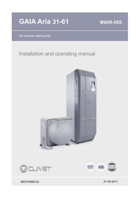
<strong>GAIA</strong> <strong>Aria</strong> <strong>31</strong>-<strong>61</strong> MSER-XEE<br />
Air source heat pump<br />
Installation and operating manual<br />
M03T40M0-02 21-04-2011
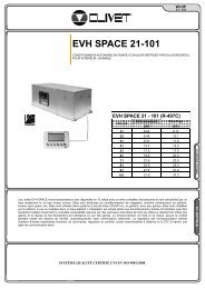
Clearances<br />
H1 H L1 L L2 W1 W W2<br />
200 2030 800 800 100 500 600 800<br />
Maximum distance<br />
A max 80 m keypad in remote positioning (1)<br />
B max 25 m refrigerant pipes<br />
C1 = B + C max 20 m outdoor air temperature probe(2)<br />
D max 15 m height difference<br />
E 6 m 6 m back up → siphon<br />
The unit must not be trailed: the feet can be broken!<br />
2<br />
Clearances<br />
<strong>GAIA</strong><br />
<strong>31</strong><br />
<strong>61</strong><br />
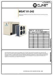
How to access the unit<br />
H L1 L L2 W1 W W2<br />
845 800 860 300 300 720 800<br />
1304 800 1250 300 300 788 800<br />
Electrical connections 230/1/50 Electrical connections 400/3/50 +N<br />
3<br />
L-N, PE<br />
3<br />
10<br />
L-N, PE<br />
2<br />
SIGNAL 10 SIGNAL<br />
1 A B C 2<br />
!<br />
E<br />
D<br />
C1<br />
5<br />
L1-L2-L3 N, PE<br />
Serial number label ( 1 )<br />
Write data and communicate<br />
them to the assistance service in<br />
case of intervention request.<br />
4<br />
L1-L2-L3 PE<br />
1<br />
1<br />
2
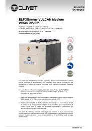
navigation<br />
Select (rotate)<br />
Confirm (press)<br />
Previous menu (pressure)<br />
Main menu (pressure)<br />
Boiler<br />
Active pump<br />
DWH production<br />
Defrosting<br />
Aux. heart<br />
Solar panels<br />
Before any operation carefully read the<br />
GENERAL WARNINGS at the end of the manual<br />
MULTIFUNCTION KEYPAD<br />
Display<br />
3<br />
Empty battery<br />
Heating<br />
Cooling<br />
Alarm in progress<br />
Compressor not timed<br />
Timed compressor<br />
quick access to menu<br />
modification of the ambient setpoint<br />
Off-Comfort-Eco-Automatic<br />
(pressure)<br />
Heating-Cooling<br />
(pressure)<br />
Fast forwards “Alarms” access (if present)<br />
Fast backwards<br />
Ambient thermostat mode<br />
Environment temperature<br />
and humidity reading.<br />
Environment thermostat<br />
function.<br />
Environment scheduling.<br />
Ven. 17/10/08 18:02<br />
Stato ECO<br />
Setpoint 20.7 100 %<br />
T Amb 18.0<br />
T Ext 45.0<br />
Unit interface mode<br />
Access to the unit<br />
configuration parameters.<br />
Ven. 17/10/08 18:02<br />
Stato ECO<br />
Setpoint 20.7 100 %<br />
T In 18.0<br />
T ACS 45.0<br />
To switch from one mode to another :<br />
remove the lid at the base<br />
move the DIP under the base.<br />
Ambient thermostat Unit iterface
Dear Customer,<br />
We congratulate you on choosing an ELFOSystem product, the air conditioning<br />
system at annual cycle that offers the possibility in a sole system of<br />
meeting all the heating, conditioning and domestic hot water needs.<br />
Clivet is being working for years to offer systems able to assure the maximum<br />
comfort for long time with high reliability, efficiency , quality and safety.<br />
The target of the company is to offer advanced systems, that assure<br />
the best comfort, reduce the energy consumption, the installation and maintenance<br />
costs for all the life-cycle of the system.<br />
With this manual, we want to give you information that are useful in all the<br />
phases: from the reception, to the installation and use until the disposal so<br />
that a system so advanced offers the best procedure of installation and use.<br />
Best regards and have a nice reading !<br />
CLIVET Spa<br />
4
DESCRIPTION <strong>GAIA</strong><br />
Packaged unit for the comfort by using renewable<br />
Energy.<br />
Integrated system for the recovery of the solar Energy<br />
from thermal correctors.<br />
Integrated production of domestic hot water.<br />
HYDRAULIC DISTRIBUTION<br />
The secondary circuits<br />
<strong>GAIA</strong> can handle up to three different zones with<br />
systems at different temperatures:<br />
low consumption, direct current circulators<br />
automatic modulation of the water flow rate based<br />
on the temperature difference<br />
optional mixing valve to obtain a different water<br />
temperature based on the type of terminal<br />
variable water temperature for each circuit<br />
according to external temperature.<br />
The hydraulic separator<br />
Permits hydraulic separation between the unit and<br />
system, ensuring perfect <strong>GAIA</strong> operation.<br />
The primary circuit<br />
Low consumption, direct current circulator<br />
Water flow rate adjusted to the variation in compressor<br />
speed maximises the exchange efficiency regardless<br />
of the variations in flow rate required by the system.<br />
The sludge remover<br />
The sludge remover eliminates particles of dirt, rust<br />
and sludge deposits from the system, which could<br />
cause considerable damage to the terminals, valves,<br />
pumps and exchangers, guaranteeing system<br />
performance and reliability over time.<br />
INTEGRATED DOMESTIC HOT WATER<br />
PRODUCTION<br />
Storage tank 200 litres<br />
Domestic hot water recirculation<br />
<strong>GAIA</strong> avoids wasting water and energy thanks to the<br />
possibility of managing DHW recirculation with a<br />
dedicated circulator, which is operated according to<br />
the schedule defined upon the initial start-up of the<br />
unit.<br />
Hot water always guaranteed<br />
If critical conditions or malfunctions are detected, Gaia<br />
automatically activates an electric safety heater in<br />
order to guarantee the constant availability of domestic<br />
hot water.<br />
GENERAL<br />
5<br />
With <strong>GAIA</strong>, it is also possible to set the time for an anti<br />
-legionella cycle.<br />
Burn-proof thermostatic valve<br />
This is used to define the temperature of the domestic<br />
hot water delivered to the system independently of the<br />
temperature of the water contained in the storage<br />
tank, with a particular burn-proof function that act in<br />
case of supply problems from the aqueduct.<br />
Domestic hot water expansion vessel<br />
HIGH ENERGY EFFICIENCY AND REDUCED<br />
CONSUMPTIONS<br />
Direct current inverter compressor<br />
Thanks to automatic capacity modulation, the direct<br />
current inverter compressor supplies only the thermal<br />
energy that is strictly necessary, thereby avoiding<br />
useless wasting of energy and increasing the energy<br />
efficiency so that the exchange surfaces are larger in<br />
relation to the output capacity.<br />
INTEGRATED SOLAR ENERGY RECOVERY<br />
SYSTEM<br />
<strong>GAIA</strong> has been designed to be connectable to solar<br />
heating panels.<br />
This will further increase the use of renewable sources<br />
to produce free domestic hot water, through solar<br />
energy captured by solar panels.<br />
The control guarantees the production of domestic hot<br />
water with the best energy efficiency possible,<br />
favoring, when possible, direct solar energy through<br />
the solar panels, or using indirect energy contained in<br />
the air through the heat pump.<br />
Domestic hot water temperature up to 80°C<br />
When the water is heated by the solar panels, it can<br />
reach a maximum temperature of 80°C. This set point<br />
is specific for production with solar heat.<br />
Outdoor climatic compensation<br />
The water temperature for the system is automatically<br />
adjusted based on the real requirements of the<br />
building and the outdoor temperature, which increases<br />
energy efficiency.
Multifunction keypad<br />
The electronic control lets to freely establish<br />
temperature, humidity, and operating times.<br />
Once set, the control manages the operation :<br />
Operating mode Summer, Winter, Domestic Hot<br />
Water only<br />
Outlet water temperature with climatic or fixed point<br />
setting for each hydraulic circuit in the unit<br />
Domestic hot water temperature from the heat<br />
pump and from solar<br />
Anti-legionella cycle<br />
Sanitary recirculation timing<br />
Operating parameters with user and installer<br />
dedicated menus<br />
Alarm signals<br />
PLANT LAYOUT<br />
A condensate water draining<br />
B cooling pipes<br />
C electrical connections<br />
D probe solar panels<br />
E external temperature probe<br />
F power supply<br />
G water supply (acqueduct)<br />
H solar panels unit (not provided)<br />
GENERAL<br />
6<br />
Maintenance of the correct system water<br />
temperature for the re-start even if the unit is off<br />
Remote control of the keyboard for timed<br />
thermostat operation, weekly scheduling, room<br />
humidity and temperature measurement.<br />
7 programs with setting of daily time band<br />
Variation of the outlet temperature based on the<br />
dew point calculation for the hydraulic circuits in<br />
reference to the room in which the HID-H1M<br />
keyboard is installed.<br />
I solar panels (Not Provided )<br />
L DHW use<br />
M DHW recirculation circuit<br />
N multifunction keypad<br />
O zone ambient thermostat (not provided)<br />
P zone ambient thermostat (not provided)<br />
Q system / DHW discarge<br />
It is not provided the solar pump control
DELIVERY CONTROL<br />
Before accepting the delivery you have to check:<br />
that the unit hasn’t been damaged during transport.<br />
Check that the materials delivered correspond with<br />
that indicated on the transport document comparing<br />
the data with the identification label ‘A’ positioned on<br />
the packaging.<br />
In case of damage or anomaly:<br />
Write down on the transport document the damage<br />
you found and quote this sentence: "Conditional<br />
acceptance clear evidence of deficiencies/damages<br />
during transport".<br />
Contact supplier and the carrier by fax and<br />
registered mail with advice of receipt.<br />
Any disputes must be made within the 8 days following<br />
the delivery. Complaints after this period are invalid.<br />
HANDLING<br />
Internal unit<br />
Lifiting with forks:<br />
Insert the forks on the long side of the pallet to<br />
avoid damaging the panelling.<br />
Lifting with crane:<br />
Position the lifting belts on the long side of the<br />
pallet .<br />
Use protection and spacers to avoid damaging the<br />
unit.<br />
Exceeding the maximum inclination allowed as<br />
indicated in the picture is prohibited.<br />
Energy exchanger<br />
Lifiting with forks:<br />
Insert the forks by the small side of the pallet.<br />
Lifting with crane:<br />
Position the lifting belts on the long side of the<br />
pallet.<br />
Use protection and spacers to avoid damaging the<br />
unit.<br />
1 - RECEPTION<br />
Before any operation carefully read the<br />
GENERAL WARNINGS at the end of the manual<br />
7
MAXIMUM DISTANCE<br />
1 A B C 2<br />
Refrigerant pipes: in vertical sections ensure the<br />
presence of siphons every six metres of unevenness<br />
(on the supply/suction line only).<br />
ENERGY EXCHANGER<br />
Clearances<br />
The space '1' can be occupied by objects that must be<br />
easily removeable in case of maintenance<br />
interventions.<br />
<strong>GAIA</strong><br />
<strong>31</strong><br />
<strong>61</strong><br />
Assembly kit<br />
H L1 L L2 W1 W W2<br />
845 800 860 300 300 720 800<br />
1304 800 1250 300 300 788 800<br />
A Antivibrators<br />
B<br />
C<br />
Gasket<br />
Connection to weld<br />
Pipe union<br />
Gasket<br />
Connection to weld<br />
Pipe union<br />
!<br />
E<br />
D<br />
2 - INSTALLATION<br />
C1<br />
8<br />
A max 80 m keypad in remote positioning (1)<br />
B max 25 m refrigerant pipes<br />
C1 = B + C max 20 m outdoor air temperature probe(2)<br />
D max 15 m height difference<br />
E 6 m 6 m back up → siphon<br />
The probe must be connected either to the energy<br />
exchanger or, alternatively, to the internal unit.<br />
<strong>GAIA</strong> <strong>31</strong><br />
<strong>GAIA</strong> <strong>61</strong><br />
A<br />
B<br />
A B<br />
C<br />
C
Direction of air supply<br />
The unit is delivered with the delivery in position 1.<br />
The air delivery may be directed in four different<br />
directions depending on the installation location .<br />
Per modificare l’orientamento:<br />
Unscrew the M6 fixing bolts on the fan cap.(4 for<br />
<strong>GAIA</strong> <strong>31</strong>, 10 for <strong>GAIA</strong> <strong>61</strong>) .<br />
Remove the cap and rotate in the required<br />
direction.<br />
Fix the cap using the bolts previously removed.<br />
Supply ducting<br />
To duct the air delivery (M):<br />
Unscrew the fixing screws and remove the<br />
protective grill.<br />
Connect the expulsion duct to the mouth of the<br />
fan using a anti-vibration joint.<br />
Return ducting<br />
To duct the air intake (R):<br />
Connect the intake duct to the flange present on<br />
the battery side using an anti-vibration joint.<br />
Fix the ducting using the threaded inserts present<br />
on the structure .<br />
After having carried out the electric connections set<br />
the fan parameters in accordance with the following<br />
indications:<br />
Ventilation<br />
Configuration paramenter<br />
(by pwd)<br />
Ducted 495 = MaxFan = 70%<br />
Non ducted<br />
495 = MaxFan = 60 %<br />
(default value)<br />
2 - INSTALLATION<br />
9<br />
R<br />
M<br />
<strong>GAIA</strong> <strong>31</strong><br />
<strong>GAIA</strong> <strong>61</strong>
2 - INSTALLATION<br />
CONNECTION FLANGE WITH EXHAUST AIR DUCT IN THE BASEMENT - OPTION<br />
This accessory allows to connect the exhaust air of the<br />
Energy exchanger to a duct in the basement by simply<br />
turning down the cap of the unit.<br />
The flange must be fixed directly to the mouth of the<br />
caps.<br />
Hole dimensions for ducting<br />
240<br />
<strong>GAIA</strong> <strong>61</strong><br />
<strong>GAIA</strong> <strong>31</strong> <strong>GAIA</strong> <strong>61</strong><br />
450<br />
Flange dimensions.<br />
<strong>GAIA</strong> <strong>31</strong><br />
327<br />
247<br />
327.5<br />
Flange provided in 2 parts<br />
247.5<br />
50<br />
119<br />
346<br />
1.5<br />
50<br />
340<br />
329 329<br />
24<br />
O 10<br />
537<br />
457<br />
201 201<br />
25 201 201<br />
804<br />
19.5<br />
800<br />
19.5<br />
196<br />
97<br />
97<br />
51.5<br />
51.5<br />
24<br />
10<br />
1<br />
2<br />
3<br />
4<br />
Put the gasket “A “on the flange<br />
A<br />
Position the cap facing to the duct.
Condensate draining<br />
Water is produced when operating the heat pump due<br />
to the defrosting cycle of the external batteries.<br />
During prolonged periods of particularly cold weather<br />
the condensate could freeze blocking the flow and<br />
generating an accumulation of ice which could<br />
increase with time.<br />
The unit is equipped with an anti-freeze resistance<br />
that stops water from freezing inside the unit.<br />
The condensate must be drained so that it does not<br />
freeze:<br />
Connect a conduit to the attachment present on<br />
the unit.<br />
Fix using the pipe clamp.<br />
Orient the conduit towards the area suitable for<br />
the discharge.<br />
Maintain an inclination of 2% to guarantee the<br />
regular flow of the condensate.<br />
To avoid freezing of the water downstream of the<br />
drain lay the tube below the frost line (A).<br />
INTERNAL UNIT<br />
Clearances<br />
Keep to the indicated safety spaces.<br />
The spaces can be occupied by objects that must be<br />
easily removeable in case of maintenance<br />
interventions.<br />
The rear space ‘L2’ of 100 mm must always be<br />
respected .<br />
2 - INSTALLATION<br />
11<br />
2%<br />
Min. 900 mm.<br />
A<br />
A Frost line<br />
H1 H L1 L L2 W1 W W2<br />
200 2030 800 800 100 500 600 800
Assembly kit<br />
The unit is equipped with:<br />
1 - kit Multifunction keypad + Outdoor air<br />
temperature probe<br />
2 - Installation manual<br />
3 - Protective barrier kit<br />
4 - Assembly kit<br />
Kit components:<br />
A Supporting feet<br />
B Antivibrators for feet<br />
C Aqueduct water filter<br />
D Gasket<br />
Connection to weld<br />
Pipe union<br />
E Gasket<br />
Connection to weld<br />
Pipe union<br />
F Outdoor air temperature probe<br />
G Batteries<br />
H Multifunction keypad<br />
I Sound proofing protective barrier<br />
L Screws for protective barrier<br />
Assembly of protective guards<br />
Assemble as indicated in the figure using the screws<br />
provided.<br />
Position on the rear of the unit<br />
leaving the air intake grill free<br />
inserting the upper flange of the protective barrier<br />
in slot ‘A’.<br />
Fix using the screws provided.<br />
Levelling unit<br />
Position the internal unit on a flat, level surface .<br />
Use a 12 spanner to adjust the support feet and level<br />
the position of the internal unit. .<br />
2 - INSTALLATION<br />
12<br />
1<br />
2<br />
3<br />
4<br />
A B C D E<br />
H G F<br />
I<br />
L
HYDRAULIC CONNECTION<br />
1 DHW delivery<br />
2 DHW recirculation<br />
3 Water supply<br />
4 System supply 3° booster<br />
5 System return 3° booster<br />
6 System supply 2° booster<br />
7 System return 2° booster<br />
8 System delivery<br />
9 System return<br />
10 Solar system delivery<br />
11 Solar system return<br />
12 Net filters<br />
13 Anti-vibration joints<br />
14 Cut-off valves<br />
In the tightening operations always use the wrench<br />
and backup wrench.<br />
EXPANSION TANK<br />
<strong>GAIA</strong> is standard supplied with:<br />
expansion tank for water technical<br />
12 lt capacity<br />
precharged at 1 bar<br />
3 - WATER CONNECTIONS<br />
expansion tank for domestic hot water<br />
8 lt capacity<br />
precharged at 2.5 bar<br />
The volume of the expansion tank for water tecnica is sufficient for<br />
systems up to:<br />
700 lt radiant panels hot only water 35°C<br />
700 lt radiant panels hot and cold water 35°C , 18°C<br />
400 lt thermal hydronic terminals hot and cold water 45°C , 7°C<br />
250 lt radiators hot only water 55°C<br />
The pressure of the expansion tank for water tecnica is sufficient for<br />
systems with a max. drop of 10 mt .<br />
For drops higher than 12 mt, calculate the pressure to charge the tank<br />
using the formula sideways.<br />
WATER INPUT<br />
Water supply input : Ø 1/2"<br />
BOOSTER<br />
R1<br />
System water input : Ø 1"<br />
System water supply : Ø 1"<br />
R2 / R3<br />
System water input : Ø 3/4"<br />
System water supply : Ø 3/4"<br />
13<br />
12 13 14<br />
= 20 mt<br />
p charge (bar) = H (mt) / 10,2 + 0,3<br />
example : p = 20 / 10,2 + 0,3 = 2,3 bar<br />
1<br />
2<br />
3<br />
4<br />
5<br />
6<br />
7<br />
8<br />
9<br />
10<br />
11
DWH<br />
DHW delivery : Ø 1/2"<br />
DHW recirculation : Ø 3/8" gas<br />
SOLAR SYSTEM<br />
Solar system water inlet : Ø 3/4"<br />
Solar system water supply : Ø 3/4"<br />
If the solar system is present an additional<br />
expansion vase will be needed.<br />
The ACS expansion vase by <strong>GAIA</strong> is sized for water<br />
up to 55 °C.<br />
Solar probe<br />
The solar panels are equipped with:<br />
a control panel<br />
a temperature probe (not provided by Clivet)<br />
For their operating with solar panels:<br />
place the temperature probe on well ‘A’ positioned<br />
on the storage tank<br />
carried out the electrical connections<br />
the solar system must be enabled (see page 33).<br />
3 - WATER CONNECTIONS<br />
14<br />
A<br />
A Solar probe well
CHARGE<br />
1. Before charging, position the systems general<br />
switch in the 'off' position .<br />
2. Check that the draining taps of the system are<br />
closed (1B).<br />
3. Check that the draining taps of the system DWH<br />
are closed (1A).<br />
4. Open all of the bleeding valves of the unit (2B).<br />
5. Open all of the bleeding valves of the unit, system<br />
and relative terminals.<br />
6. Open the system's cut-off devices .<br />
7. Open the tap of the pressure reducer (2A)<br />
8. Start the filling slowly opening the water loading<br />
tap (3A).<br />
9. When water begins to exit from the bleeding valve,<br />
close and continue the charging until the pressure<br />
intended for the system (1-2 bar) is read on the<br />
manometer (1C).<br />
10. Calibrate the pressure reducer (2A).<br />
The system is charged at a pressure of between 1<br />
and 2 bar.<br />
11. Check the hydraulic seal of the joints. Repeat the<br />
operation after the unit has operated for a number<br />
of hours and periodically control the system<br />
pressure.<br />
Reintegration is carried out when the unit is off<br />
(pump OFF).<br />
PRESSURE REDUCER<br />
Working standard calibration : 3 Bar<br />
Calibration range : 1.5 - 4 Bar<br />
1 turn = 0.5 Bar<br />
Pout = Pcalibration + (Pin - Pta) / 10<br />
E.g. : Pcalibration = 3 Bar, Pin = 4 Bar, Pout = 3.1 Bar<br />
3 - WATER CONNECTIONS<br />
15<br />
1<br />
2<br />
3<br />
1A 1B<br />
3A<br />
1C
CONNECTION TO EXTERNAL STORAGE<br />
Is possible to combine an external DHW accumulation,<br />
provided by the customer.<br />
Example:<br />
Gaia + additional tank<br />
A - Diameter of recirculation between the tanks = 3/8";<br />
Piping length between the tanks = 2,5 mt.;<br />
B - Diameter of piping between the tanks = 3/4";<br />
Piping length between the tanks = 4,5 mt.;<br />
Capacity = 0.40 m3/h<br />
Gaia + additional tank + system recirculation<br />
A - Diameter of recirculation between the tanks = 3/8";<br />
Piping length between the tanks = 2,5 mt.;<br />
B - Diameter of piping between the tanks = 3/4";<br />
Piping length between the tanks = 4.5 m.;<br />
Capacity between the two tanks = 0.3 m3/h<br />
C - Diameter of system recirculation = 3/8";<br />
System piping length = 30 mt.;<br />
D - Diameter of system piping = 1/2";<br />
Piping length between the tanks = 30 mt.;<br />
Capacity of system recirculation = 0.13 m3/h<br />
3 - WATER CONNECTIONS<br />
16<br />
1 Calibration valve - supplied by Customer<br />
2 Mixture valve - supplied by Customer<br />
3 Accumulation build-up - supplied by Customer<br />
4 Auxiliary coupling - 3/4"<br />
5 Recirculation inlet - 3/8"
DUCTING CONNECTION<br />
Use only copper pipes for refrigeration,<br />
specifications for R410A<br />
Pipes must be clean.<br />
On vertical sections ensure the presence of<br />
siphons every six metres of unevenness on the<br />
delivery/suction line only.<br />
Plug the ends of the pipe prior to passing it through<br />
a hole in the wall (1).<br />
Do not place the ends of pipes which have not been<br />
plugged or closed with tape directly on the ground<br />
(2).<br />
If the installation of the pipes is not to be completed<br />
within the next day or for a long period of time,<br />
braze the ends of the pipes and introduce nitrogen<br />
oxide via a Schrader valve access joint to avoid the<br />
formation of humidity and the contamination of the<br />
particles.<br />
Type of pipes <strong>GAIA</strong> <strong>31</strong> <strong>GAIA</strong> <strong>61</strong><br />
Liquid Ø external 1/2” 5/8”<br />
Gas Ø external 5/8” 3/4”<br />
Min. thickness 1,0 mm 1,0 mm<br />
Internal unit<br />
Remove the connection covers (1)<br />
Before attaching the ducting to the two units,<br />
clean with dry air or nitrogen.<br />
Energy exchanger<br />
The exchanger is shipped with a nitrogen charge of<br />
about 1 bar.<br />
If it is discharged, test the leaks also before the<br />
connections.<br />
Insulate pipes.<br />
Use insulation with resistance t = 120 ° C with a<br />
thickness of at least 13 mm.<br />
A Liquid ducting<br />
B Gas ducting<br />
C Electric cables<br />
D Insulation<br />
E Sheath - sticky tape<br />
4 - REFRIGERATING CONNECTIONS<br />
17<br />
A<br />
A max 25 m<br />
B max 15 m<br />
E<br />
A<br />
C<br />
D<br />
!<br />
B<br />
B
<strong>GAIA</strong> <strong>31</strong><br />
Internal unit<br />
External unit<br />
<strong>GAIA</strong> <strong>61</strong><br />
Internal unit<br />
External unit<br />
4 - REFRIGERATING CONNECTIONS<br />
18<br />
A<br />
A<br />
*<br />
*<br />
A Gas line<br />
B Liquid line<br />
1 Pipes supplied by the customer Ø external 5/8”<br />
2 Pipes supplied by the customer Ø external 1/2”<br />
* Welding points<br />
1<br />
1<br />
A Gas line<br />
B Liquid line<br />
B<br />
B<br />
1 Pipes supplied by the customer Ø external 3/4”<br />
2 Pipes supplied by the customer Ø external 5/8”<br />
* Welding points<br />
*<br />
*<br />
2<br />
2
LEAK CONTROL<br />
After having completed the refrigerating connections<br />
the sealing of the refrigerating circuit must be<br />
checked:<br />
Check that the taps of the internal unit are closed.<br />
Connect the manometric unit with the service<br />
attachments.<br />
Carry out the pressing with the refrigerant up to<br />
250KPa.<br />
Close the taps of the manometric unit<br />
disconnecting the refrigerant cylinder .<br />
Open the taps of the manometric unit to connect<br />
the nitrogen cylinder.<br />
Pressurise the system with nitrogen up to<br />
1200KPa.<br />
Check all of the ducting with a leak detection<br />
lamp or an electronic instrument paying particular<br />
attention to the welding and at joints in general.<br />
If you do not possess the instruments necessary to<br />
detect leaks leave all of the parts where a refrigerant<br />
leak is possible (welding, joints etc.) free for<br />
inspection.<br />
DRY RUN<br />
<strong>GAIA</strong> is delivered with charged refrigerator circuits in<br />
the following manner:<br />
Internal unit <strong>GAIA</strong> <strong>31</strong> 4 kg R410A<br />
Internal unit <strong>GAIA</strong> <strong>61</strong> 7.5 kg R410A<br />
Energy exchanger Nitrogen precharge<br />
Subsequent to verifying that the refrigerating circuit is<br />
hermitically sealed it is necessary to create a vacuum<br />
in the connection ducting and in the energy exchange<br />
unit:<br />
Attach the vacuum pump on both of the service<br />
attachments of the taps.<br />
Proceed with vacuum.<br />
Stop the pump at a pressure of approximately<br />
100 Pa and leave in vacuum for a few hours<br />
A small initial rise in the pressure is normal<br />
If the pressure continuing to rise is the symptom<br />
of a small leak or the presence of humidity. In the<br />
case of a leak repeat the operations described in<br />
the paragraph concerning the control of leaks in<br />
the refrigerant ducting manual. In the presence of<br />
humidity recharge the system with refrigerant gas<br />
up to 100kpa and repeat the vacuum as<br />
described above. Once the pressure is stable<br />
continue on to the successive charging phase.<br />
4 - REFRIGERATING CONNECTIONS<br />
19<br />
A Internal unit<br />
B Energy exchanger<br />
A Internal unit<br />
B Energy exchanger<br />
R410A<br />
R410A
ADDED CHARGE<br />
The refrigerant present in the internal unit must be<br />
reintegrated with the quantity for the energy exchanger<br />
and for lengths of ducting exceeding 5 metres based<br />
upon that shown in the table.<br />
Added charge for energy exchanger<br />
<strong>GAIA</strong> <strong>31</strong> 2.9 kg R410A<br />
<strong>GAIA</strong> <strong>61</strong> 3.5 kg R410A<br />
Further refill for distance<br />
exceeding 5 metres<br />
4 - REFRIGERATING CONNECTIONS<br />
0,01 kg / m<br />
To carry out the charging:<br />
With the system empty close the taps of the<br />
manometric unit and disconnect the vacuum<br />
pump.<br />
Attach the refrigerant gas cylinder using the<br />
manometric unit to allow the air to escape in the<br />
rubber connection.<br />
Open the taps of the manometric unit and pump<br />
the liquid refrigerant.<br />
Once the charging has been completed open the<br />
gas tap so that the unit is ready to be started.<br />
20<br />
A Internal unit<br />
B Energy exchanger<br />
R410A
ELECTRIC LINES INLET<br />
Internal unit<br />
The holes for passing the electric lines are on the<br />
upper part of the unit.<br />
Remove the protection cover of the hole selected.<br />
Insert the connection cable.<br />
Pass the cable between the 2 expansion tanks<br />
and and insert it behind the electrical panel. (see<br />
figure)<br />
Connect the cable to the main isolator switch.<br />
Carry out the connection in accordance with the<br />
electric connection layout .<br />
Isolator switch<br />
Connect the line to the main isolator switch inside the<br />
electrical panel.<br />
The minimum section is calculated using a cable type<br />
FG7(0) R 0,6/1 KV .<br />
It is used a different type of cable, the section must be<br />
recalculated by the designer of the electrical system.<br />
STANDARD UNIT<br />
UNIT WITH ELECTRIC<br />
RESISTANCES<br />
Size Voltage SECTION (mm 2 ) SECTION (mm 2 )<br />
<strong>31</strong><br />
<strong>61</strong><br />
<strong>61</strong><br />
Energy exchanger<br />
The holes for passing the electric lines are present on<br />
the small cover panel of the terminal strip.<br />
Remove the small panel<br />
MIN MAX MIN MAX<br />
230/1/50 4 35 16 35<br />
230/1/50 16 70 35 70<br />
400/3/50 4 35 6 35<br />
Remove the fairlead from the hole selected.<br />
Make a hole in the fair lead and insert the<br />
connection cable.<br />
Carry out the connection in accordance with the<br />
electric connection layout .<br />
5 - ELECTRICAL CONNECTIONS<br />
21<br />
A Power connections inlet<br />
B Signal connections inlet<br />
<strong>GAIA</strong> <strong>31</strong><br />
<strong>GAIA</strong> <strong>61</strong><br />
230/1/50<br />
400/3/50<br />
B A<br />
L1<br />
A Power connections inlet<br />
B Signal connections inlet<br />
L<br />
QS1<br />
N<br />
QS1<br />
L2<br />
L3 N<br />
A<br />
B<br />
PE N L<br />
PE N L3 L2 L1
5 - ELECTRICAL CONNECTIONS<br />
CONNECTION BETWEEN INTERNAL UNIT AND ENERGY EXCHANGER<br />
Carry out the connections following the layout shown<br />
To make the connections press the lever of the clamp with a screwdriver,<br />
insert the cable and release the lever.<br />
Ensure that the cable is correctly inserted and blocked in the clamp.<br />
Once the connections are made block the cables on the supports present<br />
on the base of the electric panel using a stay.<br />
The connection terminal strips may be the overlapping kind.<br />
Please refer to the figure shown to identify the clamp by its numeration.<br />
Section of the connection cables:<br />
Min. : 1,5 mm 2 AWG 15<br />
Max. : 2,5 mm 2 AWG 13<br />
X1<br />
230/ 1 / 50<br />
L1<br />
11<br />
FU3<br />
N1<br />
12<br />
X1<br />
X1<br />
XV<br />
PE<br />
PE<br />
POWER SUPPLY connection<br />
CABLE SIGNAL connection<br />
3<br />
8<br />
XC1<br />
12<br />
7<br />
22<br />
XC5<br />
13 14 15 16<br />
1 2 3 4<br />
X1<br />
X1<br />
Electric panel:<br />
connections position<br />
400/ 3 / 50+ N<br />
XV<br />
L1 L2 L3<br />
11 12 13<br />
X1<br />
25 26 35 36<br />
9 10 6 5<br />
PE<br />
PE
OUTDOOR AIR PROBE<br />
POSITIONING<br />
The sensor must not be influenced by factors that can<br />
cause a false reading (for example direct sun rays, air<br />
expelled by the fan or other sources, contact with the<br />
unit structure or other heat sources, accumulation of<br />
snow/ice).<br />
Example for the positioning of the external probe:<br />
A Attic<br />
B Underneath a terrace<br />
C If attached to external wall provide a small<br />
roof framework<br />
NORTH positioning to North enables to avoid direct<br />
thermal radiation from the sun.<br />
To position the fresh air probe:<br />
Unscrew the fixing screws and remove the cover<br />
of the probe .<br />
Fix the base of the probe to a wall using suitable<br />
pressure bolts .<br />
Carry out the electrical connections<br />
Reposition the cover and fix with the screws .<br />
CONNECTION<br />
The outdoor air probe can be connected either to the<br />
energy exchanger or, alternatively, to the internal unit.<br />
Section of the connection cables:<br />
Min. : 1,5 mm 2 AWG 15<br />
Max. : 2,5 mm 2 AWG 13<br />
5 - ELECTRICAL CONNECTIONS<br />
Probe connected to the INTERNAL unit Probe connected to the EXTERNAL unit<br />
Max 20 m.<br />
13<br />
1<br />
XC5<br />
X1<br />
14<br />
2<br />
X1<br />
X1<br />
23<br />
Max 20 m.<br />
3<br />
8<br />
NORD<br />
XC5<br />
X1<br />
12<br />
7<br />
X1
The keypad can be placed in a remote position for two<br />
different reasons :<br />
• possibility of remote interfacing with the unit;<br />
• to be used as an ambient thermostat with<br />
temperature management by the booster.<br />
In this case, the dip-switch D must be in OFF(fig.3)<br />
For the remotely install the keypad in ambient, it is<br />
necessary the accessory:<br />
TASRX - Multifunction keypad support<br />
Install the keypad away from heat sources (heating<br />
unit, sunrays, kitchen) and from doors/windows etc.<br />
To position the support (accessory):<br />
• Remove the upper cover.<br />
• Carefully move the electronic cards.<br />
• Mark out the fixing holes using the base of the<br />
support as a template.<br />
• Make a hole in the wall and fix using suitable screws<br />
and pressure bolts.<br />
In case of installations with radiant panels the humidity<br />
sensor on the keyboard allows to prevent the<br />
condensate during the summer operation.<br />
5 - ELECTRICAL CONNECTIONS<br />
MULTIFUNCTION KEYPAD AT REMOTE POSITION<br />
• Carry out the connections following the layout<br />
shown.<br />
• Position the dip-switch D as in Fig. 4<br />
• Once the connections are made block the cables on<br />
the supports present on the base of the electric<br />
panel using a stay.<br />
24<br />
1<br />
2<br />
3<br />
4A<br />
OK 1,5 m 1,5 m<br />
A MAX 80 m.<br />
B<br />
XC5<br />
38<br />
2<br />
20<br />
C<br />
A built-in card<br />
B keypad support<br />
C connection cable<br />
3x0.34 mm 2 shielded<br />
D dip-switch :<br />
1 2 3 4<br />
unit keypad 4B ambient thermostat<br />
D
BOOSTER MANAGEMENT<br />
It is possible to manager up to 3 boosters: they can be<br />
controller by HID-H1 keypad and room thermostats.<br />
HID-H1M can controls also 2 boosters together.<br />
Set the unit parameters (by pwd) in function of the type of<br />
system :<br />
R1 Par. 871 pump control 0= FROM digital input,<br />
1= From HID-H1M, 2= Both<br />
R2 Par. 909 pump control 0= FROM digital input,<br />
1= From HID-H1M, 2= Both<br />
R3 Par. 910 pump control 0= FROM digital input,<br />
1= From HID-H1M, 2= Both<br />
A Built-in card<br />
R1 Booster 1 pump control<br />
R2 Booster 2 pump control<br />
R3 Booster 3 pump control<br />
EXAMPLE 1 - unit configured with:<br />
• HID-H1M keypad on board<br />
• Booster 1 standard<br />
• Booster 2 mixed (option)<br />
• Booster 3 mixed (option)<br />
Booster 1:<br />
• High temperature<br />
• Setpoint defined by par 51 and 52<br />
• Request from room thermostat (terminals 42 and 41)<br />
Booster 2:<br />
• Mixed<br />
• Setpoint defined by par 55 and 56<br />
• Request from room thermostat (terminals 46 and 45)<br />
Booster 3:<br />
• Mixed<br />
• Setpoint defined by par 57 and 58<br />
• Request from room thermostat (terminals 8 and 7)<br />
EXAMPLE 2 - unit configured with:<br />
• HID-H1M keypad in ambient<br />
• Booster 1 standard<br />
• Booster 2 mixed (option)<br />
• Booster 3 mixed (option)<br />
Booster 1:<br />
• High temperature<br />
• Setpoint defined by par 51 and 52<br />
• Request from room thermostat (terminals 42 and 41)<br />
Booster 2:<br />
• Mixed<br />
• Setpoint defined by par 55 and 56<br />
• Request from room thermostat (terminals 46 and 45)<br />
Booster 3:<br />
• Mixed<br />
• Setpoint defined by par 57 and 58<br />
• Request from HID-H1M keypad<br />
5 - ELECTRICAL CONNECTIONS<br />
25<br />
E1<br />
E2<br />
Main menu<br />
configuration<br />
XC5<br />
A<br />
unit<br />
Booster 1 par 871 = 0<br />
Booster 2 par 909 = 0<br />
Booster 3 par 910 = 0<br />
Booster 1 par 871 = 0<br />
Booster2 par 909 = 0<br />
Booster 3 par 910 = 1<br />
R3<br />
R3<br />
Circuit 1 (par.871)<br />
Circuit mixed<br />
R2<br />
R2<br />
41<br />
42<br />
45<br />
46<br />
7<br />
8<br />
R 1<br />
R 2<br />
R 3<br />
R1<br />
R1
INTERNAL UNIT OPTIONAL CONNECTIONS<br />
Summer - winter remote switch<br />
Permits the change in operating mode from heating to<br />
cooling by an external control.<br />
Main menu<br />
configurazione<br />
Configuration paramenters<br />
21 = 1 switch mode from unit to keyboard<br />
21 = 0 switch mode from digital inlet<br />
Second set switch (2)<br />
By an external control, it allows to select a second<br />
room setpoint optimized for a lower energy<br />
consumptions.<br />
The input is always enabled and so the setting by the<br />
parameter is not necessary.<br />
The control enables the ECO set of all the boosters,<br />
with priority for the keypad.<br />
From the HID-H1M keypad on board:<br />
Economic isolator switch<br />
Water reset - segnale 4-20 mA (3)<br />
Water reset<br />
The function enables the correction of the system<br />
water setpoint based on an external signal type 4-20<br />
mA or 0-10v.<br />
The function acts simultaneously on all the booster<br />
sets.<br />
See details on page 35.<br />
Water reset - segnale 0-10V (3a)<br />
Supervisor (4)<br />
The unit can be connected to ELFOControl or an<br />
external supervisor system.<br />
In this case follow the connections as shown.<br />
Main menu<br />
configuration<br />
macchina<br />
unit<br />
Configuration paramenters<br />
<strong>31</strong>5 ModBus supervision serial address<br />
<strong>31</strong>6 Baud Rate (0=4800 / 1=9600 2=19200) supervision serial<br />
<strong>31</strong>7 Parity 0=NO / 1=Odd 2=Even supervision serial<br />
5 - ELECTRICAL CONNECTIONS<br />
configurazione<br />
communication<br />
26<br />
1<br />
2<br />
3<br />
3a<br />
4<br />
CONNECTIONS<br />
N° of Section Nominal Impedance Recommended<br />
Ref connection (mm 2 ) capacity characteristics cable<br />
AP5<br />
cables Min Max pF/m<br />
2 twisted and<br />
shielded<br />
-<br />
+<br />
GND<br />
XC5<br />
21<br />
22<br />
XC5<br />
XC5<br />
29<br />
30<br />
XC5<br />
47<br />
48<br />
0,22 0,35
PRELIMINARY CHECKS<br />
6 - START-UP<br />
The following check list is a brief reminder of the points to check and of the operations to perform to start-up the unit.<br />
For details on the points mentioned in the check list refer to various chapters of the manual.<br />
Preliminary checks √<br />
1 Are the functional spaces of the internal unit and the energy exchanger being observed ?<br />
2 Is the section of the cooling lines correct ? Have the supplied sealing couplings been used ?<br />
3 Does the length of the cooling lines exceed 20 m ?<br />
4 Is the height difference in the cooling lines less than 15 m ?<br />
5 Are there siphons every 6 m going back up on the gas line ?<br />
6 Have emptying and additional load been carried out ? Was there a visual check for oil / leaks?<br />
7 Are the anti-vibration supports present and level?<br />
8 Is the soundproof carter mounted ?<br />
9 Is the water filter from the waterworks inlet correctly installed?<br />
10 Are the inlet and outlet of the water lines correct ?<br />
11<br />
If there are intercepting units present (heads/valves), are the unit circulator/s in arrest due to lack of water<br />
flow?<br />
12 How was the system created ? Is there a minimum water content in circulation ?<br />
13 Are the anti-vibration joints on the hydraulic connections present?<br />
14 Was the system loaded, placed under pressure and was the air let out?<br />
15 Was the solar panel control panel sensor assembled on the <strong>GAIA</strong> accumulation?<br />
16 Was the condensate produced by the energy exchanger drained correctly? Can it freeze ?<br />
17 Is the capacity of air to the energy exchanger adequate ? Is there air recirculation ?<br />
18 Have the electrical connections to the energy exchanger been made?<br />
19 Is the external air sensor positioned correctly?<br />
20<br />
Is the keyboard positioned on board the unit or in the environment? Does it act as a thermostat or as a<br />
control keyboard ?<br />
21 Have optional electrical connections been made ? (summer/winter, second set, etc….)<br />
22<br />
Is the power supply correct ? 230/1/50 or 400/3/50 ?<br />
Is the available power supply sufficient ?<br />
23 Is the booster circuit/s connected to the control circuit (digital inlet or HID-H1 in the environment) ?<br />
27
START-UP SEQUENCE<br />
6 - START-UP<br />
Start-up sequence √<br />
1 Has the carter resistance been charged for at least 8 hours ?<br />
2 Set date and time<br />
3 Check refrigerating circuit/charge function<br />
4 Calibrate thermostatic mixing valve<br />
5 Set the thermal rise of the boosters<br />
6 Calibrate recirculation sanitary (if present)<br />
7 Configure the ventilation of the energy exchanger (if channeled)<br />
8 Enable solar (if present)<br />
9 Set absorbed power limitation function (if necessary)<br />
10 Personalise system water set-point<br />
11 Personalise system climatic curves<br />
12 Personalise Water reset curve (if present)<br />
13 Personalise anti-dew compensation (if radiant panels are present)<br />
14 Sanitary water personalisation<br />
15 Personalise anti-legionella scheduling<br />
16 Personalise environment scheduling<br />
28
ANOMALIES IN ACTIVATION<br />
6 - START-UP<br />
PROBLEM CAUSE SOLUTION<br />
I01 flow alarm<br />
system with insufficient pressure, air not<br />
adequately let out, dirty sludge remover.<br />
compressor no alarm signal activates water temperature out of functioning limits<br />
i 13 Alarm water temperature out of functioning limits<br />
unit in low pressure<br />
unit in high pressure<br />
closed taps<br />
29<br />
place under pressure, check load gauge,<br />
let air out (reset alarm and proceed to let<br />
air out, clean sludge remover)<br />
TEMPORARILY disable parameter 19.<br />
(password protected)<br />
ATTENTION : the PROLONGED function<br />
out of the limits may irreversibly damage<br />
the unit<br />
TEMPORARILY disable parameter 19.<br />
(password protected)<br />
ATTENTION : the PROLONGED function<br />
out of the limits may irreversibly damage<br />
the unit<br />
open internal unit faucets and energy<br />
exchanger<br />
insufficient charge check coolant load<br />
load not executed<br />
leak in piping execute leak search<br />
excessive load check coolant load<br />
insufficient energy exchanger air capacity<br />
(summer)<br />
booster circulator does not start missed call from HID-H1 or by digital inlet<br />
clean battery.<br />
check if supply and return are obstructed<br />
by obstacles,<br />
check air capacity<br />
check if call (from 71/hid-h1) is configured<br />
correctly.
REFRIGERANT CIRCUIT<br />
1. Visually check the refrigerating circuit: the<br />
presence of oil stains can mean leakage (caused,<br />
for example, by transport, handling or other).<br />
2. Open the cocks of the refrigerator circuit, if there<br />
are any.<br />
3. Check that the refrigerating circuit is under<br />
pressure:<br />
- use the unit pressure gauges, if present, or some<br />
service pressure gauges.<br />
4. Ensure that all the service outlets are closed with<br />
the proper caps; if caps are not present a leak of<br />
refrigerant is possible.<br />
HYDRAULIC CIRCUIT<br />
1. Before realizing the unit connection make sure that<br />
the hydraulic system has been cleaned up and the<br />
clearing water has been drained .<br />
2. Check that the water circuit has been charged and<br />
pressurised .<br />
3. Check that the cut-off valves on the circuit are in<br />
the "OPEN" position.<br />
4. Check that no air is present in the circuit, if<br />
required, evacuate using the air bleeding valve<br />
placed at the system's high points.<br />
5. When using antifreeze solutions, make sure the<br />
glycol percentage is suitable for the type of use<br />
envisaged<br />
Glicol by weight (%) 10 20 30 40<br />
Freezing temperature (°C) -3.9 -8.9 -15.6 -23.4<br />
Safety temperature (°C) -1 -4 -10 -19<br />
ELECTRICAL CIRCUIT<br />
1. Verify that the unit is connected to the ground<br />
plant .<br />
2. Check tightening of the conductors: the vibrations<br />
caused by handling and transport might cause<br />
loosing .<br />
3. Feed the unit by closing the sectioning device, but<br />
leave it on OFF.<br />
4. Check the tension and line frequency values which<br />
must be within the limits:<br />
230/1/50 + / - 6%<br />
400/3/50 + / - 6%<br />
On 400/3/50 unit check that the phases unbalancing<br />
must be lower than 2%<br />
6 - START-UP<br />
30<br />
Example:<br />
DATE AND HOUR<br />
Set the date and current hour in the<br />
multifunction keypad.<br />
Insert the multifunction keypad in the support<br />
present on the unit. (The display will be turned on<br />
in the system management mode.)<br />
Main menu<br />
1)<br />
2)<br />
3)<br />
COMPRESSOR CRANKCASE RESISTANCES<br />
Feed the oil resistances on the compressor crankcase<br />
at least 8 hours before the start compressor :<br />
at the first unit start-up<br />
L1 L2 L3<br />
388V<br />
after each prolonged periods of inactivity<br />
1. Feed the resistances closing the unit isolator<br />
(sorter??).<br />
2. Control the resistances electrical absorption to be<br />
sure that they’re function .<br />
3. Carry out start-up only if the compressor crankcase<br />
temperature on the lower side must be higher at<br />
least of 10° C than the outside temperature.<br />
Do not start the compressor with the crankcase oil<br />
below operating temperature .<br />
date and hour<br />
377V<br />
379V<br />
388 + 379 + 377<br />
= 381 (A)<br />
3<br />
MAX - A = 388 – 381 = 7<br />
S =<br />
7<br />
A<br />
x 100 = 1,83 OK<br />
The working out of the limits can cause irreversible<br />
damages and voids the warranty.<br />
day<br />
month<br />
year<br />
hour
REFRIGERANT CHARGE CHECK<br />
The unit can be in DHW mode.<br />
It is important that during the measurements :<br />
- there is enough charge to maintain the unit in<br />
operation<br />
- there are no mode changes (from DHW to the<br />
installation or vice versa)<br />
Position system general switch at "On"<br />
Position main switch on unit side at “I”.<br />
The green operating indicator lights up.<br />
On the multifunction keypad:<br />
Select the required operating mode.<br />
Select required system control<br />
If the water temperature is < 25°C in heating or > 30°C<br />
in cooling, the unit will start late.<br />
Modify the following parameters (by pwd) to allow<br />
the unit operating at the 50% :<br />
382 Min Vcc = 4,9 (compressor)<br />
383 Max Vcc = 5,1 (compressor)<br />
386 Nominal Vcc = 5 (compressor)<br />
495 MaxFan = 50 (ventilation)<br />
496 MinFan = 49 (ventilation)<br />
(note the initial value so it can be reset at the end<br />
of the tests)<br />
·wait at least 15 minutes after unit start up before<br />
executing the readings<br />
NOTE: the sanitary hot water tap must be opened<br />
in order for the temperature itself in the<br />
accumulation to remain at 30 - 40 °C.<br />
Subcooling calculation :<br />
= temperature read on the high pressure gauge<br />
- temperature detected before the liquid receiver<br />
The correct subcooling is between 1,5 and 2,5 °C<br />
If the values are higher remove gas from the liquid<br />
pipe with unit in operation<br />
If the values are lower add gas, with insufficient<br />
charge the liquid light displays the presence of<br />
bubbles.<br />
Wait about 20 minutes to stabilize the unit<br />
Repeat the measure<br />
If necessary add / remove gas<br />
Once reached the optimal charge, reset the<br />
parameter to their original value.<br />
6 - START-UP<br />
<strong>31</strong><br />
Main menu<br />
configuration<br />
unit<br />
Compressor<br />
Ventilation
6 - START-UP<br />
SETTING OF THERMOSTATIC MIXING VALVE BURN-PROOF<br />
Settable, standard setting : 48°C<br />
Regulation of the valve temperature:<br />
closed = 30 °C<br />
open = 60 °C<br />
1 full turn ~ 4 °C<br />
Setting sequence :<br />
release the valve (see below )<br />
measure the output temperature<br />
unscrew the cap fixing screw<br />
lock the valve<br />
Locking / release<br />
1. unscrew the cap fixing screw<br />
2. remove the cap<br />
3. screw the locking nut<br />
4. reposition the cap, screw the cap fixing screw<br />
1 2<br />
3 4<br />
32<br />
Settable
BOOSTERS<br />
Pump head setting<br />
Thanks to the circulator in continuous current, it is<br />
possible to set the delta T nominal system that is<br />
maintained constant through the variations of the loading<br />
conditions.<br />
1. set the nominal temperature difference for each<br />
booster present with parameters (by pwd):<br />
circuit 1 par. 866 <strong>Delta</strong>TPumpC1<br />
circuit 2 par. 896 <strong>Delta</strong>TPumpC2<br />
circuit 3 par. 905 <strong>Delta</strong>TPumpC3<br />
2. activate the pump of each booster :<br />
- from multifunction keypad (increase or decrease the<br />
DHW RECIRCULATION CALIBRATION<br />
Normally is it sufficient to enable the recirculation<br />
through time slots, rather than through changing the<br />
ON-OFF cycle of the circulator.<br />
ACS recirculation, if foreseen in the system, is carried<br />
out by making the sanitary water circulate through the<br />
unit pump.<br />
The pump alternates ON and OFF cycles with duration<br />
that may be set by parameters (password protected):<br />
p441 Recirculation Time OFF<br />
p440 Recirculation Time ON.<br />
The recirculation function is active only at the times<br />
foreseen by the ACS scheduler (maintenance+<br />
recirculation mode, accumulation + recirculation mode)<br />
see page 36.<br />
The parameters are the same that manage the antistratification<br />
recirculation in the ACS accumulation.<br />
The recirculation still causes some inefficiencies<br />
(thermal dispersions in system piping etc.) therefore<br />
duration and frequency will have to be optimised for the<br />
system.<br />
The unit is shipped with closed calibration tap.<br />
It is possible to calibrate the recirculation capacity<br />
through tap "A".<br />
VENTILATION<br />
NOMINAL CAPACITY CHANGE<br />
Based on installation conditions, it is possible to change<br />
the nominal speed of the fan.<br />
Menu:<br />
Main menu > configuration > unit > all<br />
SOLAR<br />
If the solar circuit is present, enable the function as the<br />
menu on the side.<br />
The solar activates when the Solar temperature > 8 °C<br />
than the temperature in the accumulation, and remains<br />
active until 80 °C.<br />
6 - START-UP<br />
33<br />
set-point rotating the center key)<br />
- by the calling from digital input<br />
3. detect the thermal rise on the present reboots<br />
from the unit conditions .<br />
Main menu<br />
configuration<br />
Main menu<br />
configuration<br />
A DHW recirculation enabling tap<br />
par (by pwd)<br />
495 MaxFan 70% = ducted<br />
Main menu<br />
configuration<br />
unit<br />
unit<br />
unit<br />
Circuit 1<br />
Circuit mixed<br />
DHW<br />
A<br />
60% = non ducted<br />
DHW (par.420)
ABSORBED CAPACITY LIMITATION<br />
If necessary is possible to limit the capacity absorbed<br />
by the unit to a prefixed value.<br />
par<br />
26 ENPowerLimit 0=disabled,1=enabled<br />
177 LimitePW set the maximum capacity in kW<br />
FINAL SETTINGS<br />
ID Description Extended description<br />
51 SetCool Summer Set Point<br />
52 SetHeat Winter Set Point<br />
53 SecondSetC Summer secondary SetPoint<br />
54 SecondSetH Winter secondary SetPoint<br />
55 SetCoolC2 Summer Set Point circuit 2<br />
56 SetHeatC2 Winter Set Point circuit 2<br />
57 SetCoolC3 Summer Set Point circuit 3<br />
58 SetHeatC3 Winter Set Point circuit 3<br />
59 SecondSetC2 Summer secondary SetPoint circuit 2<br />
60 SecondSetH2 Winter secondary SetPoint circuit 2<br />
<strong>61</strong> SecondSetC3 Summer secondary SetPoint circuit 3<br />
62 SecondSetH3 Winter secondary SetPoint circuit 3<br />
SYSTEM WATER CLIMATIC CURVES<br />
Set point compensation on outdoor temperature<br />
Enable the function by changing the:<br />
1. Parameter 4 On compensation (0=No,1=Cool,<br />
2=Heat,<br />
2. 3=Always)<br />
3. Return to the main screen<br />
4. Go back again in the "External T. Correction"<br />
menu”<br />
The correction is enabled for each reboot.<br />
A - Summer.<br />
With outside low temperatures the refrigerant<br />
requirements are reduced. The internal comfort can<br />
also be obtained with a set-point higher than standard.<br />
The correction is added to the set-point (increased<br />
with the decrease in temperature).<br />
B- Winter.<br />
With outside mild temperatures the thermal<br />
requirements are reduced.<br />
The internal comfort can also be obtained with a lower<br />
set-point. The correction is subtracted from the setpoint<br />
(increased with the decrease in temperature).<br />
Es: se temp. Ext. > 114, set water = par 52 -117<br />
6 - START-UP<br />
PERSONALIZATION OF THE SYSTEM WATER SET POINT<br />
Set the setpoint for the boosters.<br />
34<br />
Main menu<br />
configuration<br />
Main menu<br />
Main menu<br />
configuration<br />
116<br />
R1 R2 R3<br />
configuration<br />
unit<br />
unit<br />
configuration<br />
ESTATE<br />
INVERNO<br />
Summer Winter<br />
112<br />
unit<br />
T ext<br />
113<br />
Setpoint<br />
Configuration<br />
Demand limit<br />
115<br />
Water Reset<br />
Set point<br />
112 120 126 Ext. temp. min. summer correction<br />
113 121 127 Outdoor temp. max. summer correction<br />
114 122 128 Ext. temp. max. winter correction<br />
115 123 129 Ext. temp. min. winter correction<br />
116 124 130 Summer correction max. value<br />
117 125 1<strong>31</strong> Winter correction max. value<br />
117<br />
T ext<br />
114
WATER RESET (WATER CLIMATIC)<br />
Enable the function by changing the:<br />
1. Parameter 5 enable water reset (0=No,1=Cool,<br />
2=Heat, 3=Always )<br />
2. Return to the main screen<br />
3. Go back again to the "Water reset" menu”<br />
The function operates at the same time of all the<br />
booster sets.<br />
The function enables the correction of the system<br />
water setpoint based on an external signal type 4-20<br />
mA or 0-10v.<br />
A - Summer.<br />
If the refrigerator requirements are low the set point is<br />
increased.<br />
The correction is added to the set-point (increased as<br />
the external temperature decreases).<br />
B - Winter.<br />
If the thermal requirements are low the set point is<br />
decreased.<br />
The correction is subtracted from the set-point<br />
(increased with the decrease in temperature).<br />
ANTI-DEW COMPENSATION<br />
The function is necessary in applications with radiant<br />
panels and keyboard in environment (environment<br />
thermostat).<br />
The set point is limited downwards in order to avoid<br />
the formation of condensate on the floors.<br />
The function may be enabled through parameter 27, it<br />
is only active in cooling.<br />
6 - START-UP<br />
35<br />
Main menu<br />
configuration<br />
Summer ESTATE<br />
Winter<br />
INVERNO<br />
141 140<br />
WR=min WR=max<br />
139<br />
Setpoint<br />
Configuration paramenters<br />
5 Water reset enabling 0=No 1=Cool 2=Heat 3=Always<br />
135 It sets the WR signal: 0 = 0 - 10v, 1 = 4 - 20 mA<br />
136 Max. value of the Winter WR correction<br />
137 winter max. correction signal<br />
138 winter min. correction signal<br />
139 summer correction max. value<br />
140 summer max. correction signal<br />
141 summer min. correction signal<br />
Main menu<br />
unit<br />
configuration<br />
136<br />
unit<br />
137 138<br />
WR=max<br />
Water Reset<br />
Configuration paramenters<br />
27 Anti-dew compensation enabling<br />
Configuration (par. 5)<br />
Water reset<br />
WR=min<br />
configuration
DHW<br />
The unit always leads the DHW to the setpoint p429<br />
(by pwd) value.<br />
During the storage phase the temperature drops until<br />
par 432 (by pwd).<br />
During the maintenance phase the temperature drops<br />
until par 4<strong>31</strong> (by pwd)..<br />
It is better to schedule the maintenance phase at night<br />
and during the periods of reduced use of DHW.<br />
If the ACS set is changed, change the calibration of<br />
the thermostatic mixing valve.<br />
SCHEDULING<br />
The scheduling allows to set the daily time bands and<br />
to allocate the destre operating mode :<br />
Maintenance<br />
Maintenance + Recirculation<br />
Storage + Ricirculation<br />
Storage<br />
For details see Dhw program.<br />
ANTI-LEGIONNAIRES SCHEDULING<br />
The scheduling allows to set :<br />
Cadence:<br />
Disabled<br />
Weekly<br />
Monthly<br />
Annual<br />
Day<br />
Start hour<br />
6 - START-UP<br />
36<br />
Main menu<br />
SET<br />
p 429<br />
p 432<br />
p 4<strong>31</strong><br />
Main menu<br />
Main menu<br />
configuration<br />
scheduling<br />
scheduling<br />
unit<br />
A<br />
DHW<br />
ambient<br />
DHW<br />
programs<br />
weekly<br />
M<br />
Name modification<br />
anti-legionnaires
ACTIVE AMBIENT SCHEDULING<br />
The scheduling allows to set the daily time bands and<br />
to allocate the destre operating mode:<br />
Comfort<br />
Economic<br />
Off<br />
For details see Room scheduling.<br />
STARTING REPORT<br />
Reading the objective operating conditions is useful for<br />
checking the unit over time.<br />
With unit of full load, namely in stable conditions and<br />
close to those of work, take the following data:<br />
- Voltage and general absorptions with unit at full<br />
load<br />
- Absorption of varied electrical loads (compressors,<br />
fans, pumps etc)<br />
- <strong>Temp</strong>eratures and capacities of different liquid<br />
(water, air) in the inlet and outlet of the unit.<br />
- <strong>Temp</strong>erature and pressures on the characteristic<br />
points of the refrigerating circuit (compressor<br />
discharge, liquid, intake).<br />
The readings should be stored and made available<br />
during maintenance .<br />
6 - START-UP<br />
37<br />
Main menu<br />
Scheduling<br />
ambient<br />
programs<br />
weekly<br />
name modification
Environment thermostat mode: menu structure<br />
MAIN MENU<br />
System controls<br />
Stata *<br />
System modalities<br />
Alarms *<br />
Configuration *<br />
Scheduling<br />
Date and hour<br />
Password<br />
Off<br />
Comfort<br />
Economy<br />
Automatic<br />
Party<br />
DHW only<br />
Base Info<br />
Keypad Info<br />
Unit stata<br />
Stata I/O<br />
DHW<br />
Heating<br />
Cooling<br />
Active alarms<br />
Alarm log<br />
Alarm reset<br />
Log reset<br />
Keypad<br />
Unit<br />
System’s variables<br />
Unit<br />
DHW<br />
Anti-legionnaires<br />
* Visible only after having entered the password<br />
7 - CONTROL<br />
Keypad<br />
Setpoint<br />
Language<br />
Ven. 17/10/08 18:02<br />
Stato ECO<br />
Setpoint 20.7 100 %<br />
T Amb 18.0<br />
T Ext 45.0<br />
All the parameters<br />
Weekly<br />
Programs (7)<br />
Name modification<br />
Weekly<br />
Programs (3)<br />
Name modification<br />
38<br />
id1 timepsw<br />
id10 minielfo Ecc...<br />
setcool<br />
setcooleco<br />
setheat<br />
setheateco<br />
Mant. /Mant+ric / acc+ric / acc.<br />
Cadence : disabled / weekly / monthly / annual<br />
Day<br />
Start hour
Unit interface mode : menu structure<br />
MAIN MENU<br />
System controls<br />
System modalities<br />
Stata *<br />
Alarms *<br />
Configuration<br />
Scheduling<br />
Date and hour<br />
Password<br />
Off<br />
Comfort<br />
Economy<br />
Automatic<br />
DHW only<br />
Heating<br />
Cooling<br />
Base Info<br />
Keypad Info<br />
Unit stata<br />
Stata I/O<br />
DHW<br />
Active alarms<br />
Alarm log<br />
Alarm reset<br />
Log reset<br />
User parameters<br />
Configuration Menu *<br />
Unit<br />
DHW<br />
Anti-legionnaires<br />
* Visible only after having entered the password<br />
7 - CONTROL<br />
Keypad<br />
Unit<br />
Ven. 17/10/08 18:02<br />
Stato ECO<br />
Setpoint 20.7 100 %<br />
T In 18.0<br />
T ACS 45.0<br />
System’s variables<br />
Weekly<br />
Programs (7)<br />
Name modification<br />
Weekly<br />
Programs (3)<br />
Name modification<br />
39<br />
Keypad (id1,id10…...<br />
Language<br />
All the parameters<br />
Mant. /Mant+ric / acc+ric / acc.<br />
Cadence : disabled / weekly / monthly / annual<br />
Day<br />
Start hour
7 - CONTROL<br />
<strong>GAIA</strong> after the fisrt start-up, performed by the Installer or the CLIVET Assistance Technical Service, is controlled for an<br />
“automatic” operating and there’s no need of further interventions.<br />
The user must therefore perform the Start-up and Shutdown operations using the multifunction keypad or the remote<br />
switch (if present).<br />
Start up<br />
Position system general switch at "On"<br />
Position main switch on unit side at “I”.<br />
The green operating indicator lights up.<br />
Press to access to the “System mode” menu.<br />
Rotate to select the desired mode between Heating and<br />
Cooling.<br />
Press to confirm.<br />
Press to access to the “System controls” menu.<br />
Rotate to select the desired mode among the available.<br />
Press to confirm.<br />
SEASONAL CHANGE - Heating - Cooling.<br />
Press to access to the “System mode” menu.<br />
Rotate to select the desired mode between Heating and<br />
Cooling.<br />
Press to confirm.<br />
40<br />
Fri. 17/10/08 18:02<br />
Status ECO<br />
Heating<br />
Amb T Cooling 20.7 100 %<br />
Out T 18.0<br />
DHW T 45.0<br />
Fri. 17/10/08 18:02<br />
Status ECO<br />
Amb T 20.7 100 %<br />
Out T 18.0<br />
DHW T 45.0<br />
Main Menu<br />
System controls<br />
Off<br />
System modalities Comfort<br />
Economic<br />
System enabling<br />
Automatic<br />
Stata<br />
Fri. 17/10/08 18:02<br />
Status ECO<br />
Amb T 20.7 100 %<br />
Out T 18.0<br />
DHW T 45.0<br />
Fri. 17/10/08 18:02<br />
Status ECO<br />
Heating<br />
Amb T Cooling 20.7 100 %<br />
Out T 18.0<br />
DHW T 45.0<br />
Fri. 17/10/08 18:02<br />
Status ECO<br />
Amb T 20.7 100 %<br />
Out T 18.0<br />
DHW T 45.0
Modification of the ambient temperature<br />
Shutdown<br />
Press to access to the “System controls” menu.<br />
Rotate to select the “Off” control.<br />
Press to confirm.<br />
Press to turn off the unit.<br />
7 - CONTROL<br />
If the multifunction keypad is set as room thermostat it is possible to change the value of the desired<br />
temperature.<br />
Rotate to change immediately the setpoint.<br />
Press to confirm.<br />
41<br />
Fri. 17/10/08<br />
Setpoint<br />
18:02<br />
Status Min ECO 8.0<br />
Amb T Max 20.7 24.0 100 %<br />
Out T 21.7 18.0<br />
DHW T 45.0<br />
Fri. 17/10/08 18:02<br />
Status ECO<br />
Amb T 20.7 100 %<br />
Out T 18.0<br />
DHW T 45.0<br />
Main Menu<br />
System controls<br />
Off<br />
System modalities Comfort<br />
System enabling<br />
Economic<br />
Automatic<br />
Stata<br />
Fri. 17/10/08 18:02<br />
Status OFF<br />
Amb T 20.7 100 %<br />
Out T 18.0<br />
DHW T 45.0
Room scheduling<br />
7 - CONTROL<br />
If the system configuration allows, in addition to the start-up and shutdown operations, the multifunction keypad allows<br />
the personalization of the hourly and weekly scheduling.<br />
Press.<br />
Rotate to select the “Scheduling” menu.<br />
Press.<br />
Rotate to select the “Ambient” menu.<br />
Press.<br />
Rotate to select the “Programs” menu.<br />
Press.<br />
Rotate to select the program.<br />
Press.<br />
Press to access to the modification display.<br />
Press to confirm the choice.<br />
Select and confirm:<br />
Comfort = Com<br />
Economic = Eco<br />
Off = Off<br />
Press the previous Menu key and confirm to save the modifications.<br />
Press to go back at the main screen.<br />
42<br />
Stata<br />
Scheduling<br />
Date and hour<br />
Password<br />
Prog 1<br />
Prog 2<br />
Prog 3<br />
Prog 4<br />
Com-<br />
Eco -<br />
Off -<br />
Main Menu<br />
Scheduling Menu<br />
Ambient<br />
DHW<br />
Scheduling Menu<br />
Weekly<br />
Programs<br />
Name modification<br />
Programs<br />
P rog 1<br />
0 4 8 12<br />
16 20 24<br />
Hour : 05:00 Val : Eco<br />
Com-<br />
Eco -<br />
Off -<br />
P rog 1<br />
0 4 8 12<br />
16 20 24<br />
Hour : 18:00 Val : Eco<br />
Com-<br />
Eco -<br />
Off -<br />
P rog 1<br />
To save the<br />
modification<br />
OK<br />
0 4 8 12<br />
16 20 24<br />
Hour : 18:00 Val : Eco<br />
Fri. 17/10/08 18:02<br />
Status ECO<br />
Amb T 20.7 100 %<br />
Out T 18.0<br />
DHW T 45.0
Dhw program<br />
7 - CONTROL<br />
In addition to the start-up and shutdown operations, the multifunction allows the personalization of the hourly and<br />
weekly programming of the domestic hot water. Details on page 43.<br />
Press.<br />
Rotate to selct the “Scheduling” menu.<br />
Press.<br />
Rotate to select the “DHW” menu.<br />
Press.<br />
Rotate to select the “Programs” menu.<br />
Press.<br />
Rotate to select the program.<br />
Press.<br />
Press to modify the flashing segment of the hour.<br />
Press to confirm the choice.<br />
Select and confirm:<br />
Maintenance = Mant<br />
Maintenance + Recirculation = Mant + Ric<br />
Storage + Recirculation = Acc + Ric<br />
Storage . = Acc<br />
Press the previous Menu key and confirm to save the modifications.<br />
Press to go back at the main screen.<br />
43<br />
Stata<br />
Scheduling<br />
Date and hour<br />
Password<br />
Prog 1<br />
Prog 2<br />
Prog 3<br />
-<br />
Acc -<br />
Ric -<br />
Main Menu<br />
Scheduling Menu<br />
Ambient<br />
DHW<br />
Scheduling Menu<br />
Weekly<br />
Programs<br />
Name modification<br />
Programs<br />
P rog 1<br />
0 4 8 12<br />
16 20 24<br />
Hour : 05:00 Val : Acc+ Ric<br />
-<br />
Acc -<br />
Ric -<br />
P rog 1<br />
0 4 8 12<br />
16 20 24<br />
Hour : 08:00 Val : Acc+ Ric<br />
-<br />
Acc -<br />
Ric -<br />
P rog 1<br />
To save the<br />
modification<br />
OK<br />
0 4 8 12<br />
16 20 24<br />
Hour : 21:00 Val : Acc<br />
Fri. 17/10/08 18:02<br />
Status ECO<br />
Amb T 20.7 100 %<br />
Out T 18.0<br />
DHW T 45.0
Date and hour<br />
7 - CONTROL<br />
The date and hour settingg is requested at the first keypad use (batteries insertion), in case of replacement or after the<br />
reset.<br />
Press.<br />
Rotate to select the “Date and hour” menu.<br />
Press.<br />
Rotate to select the “Month”<br />
Press.<br />
Rotate to modify the value.<br />
Press to confirm the value.<br />
Perform the operation by year, mounth, day and minutes.<br />
Press to go back at the main screen.<br />
44<br />
Status<br />
Scheduling<br />
Date and hour<br />
Password<br />
Main Menu<br />
Clock settings<br />
Day 18<br />
Month 6<br />
Year 2009<br />
hour 10:00<br />
Clock settings<br />
Day 18<br />
Month 7 6<br />
Year 2009<br />
hour 10:00<br />
Clock settings<br />
Day 18<br />
Month 7<br />
Year 2009<br />
hour 10:00<br />
Fri. 18/07/09 10:00<br />
Status ECO<br />
Amb T 20.7 100 %<br />
Out T 18.0<br />
DHW T 45.0
Alarms<br />
7 - CONTROL<br />
Breakdowns are indicated by the luminous orange indicator present on<br />
the side of the unit and the appearance of the 'Alarm underway' symbol<br />
on the multifunctional keypad.<br />
In case of alarm shutdown the unit and immediately call the service<br />
center.<br />
On the multifunction keypad keep the central key pressed to pass in<br />
UNIT mode.<br />
Press.<br />
Rotate to select the ACTIVE ALARMS and confirm.<br />
Press.<br />
Alarm visualization.<br />
Press.<br />
Rotate to select the LOG RESET<br />
Press to confirm the reset.<br />
Press to go back at the main screen.<br />
Repeated reset can cause irreversibile damages as<br />
malfunctioning of the system itself.<br />
45<br />
E03<br />
Alarm Menu<br />
Active alarms<br />
Alarm log<br />
Alarm reset<br />
Log reset<br />
Active alarms<br />
Out. <strong>Temp</strong>. probe<br />
Date 08/08/09<br />
Hour 12:45<br />
Alarm Menu<br />
Active alarms<br />
Alarm log<br />
Alarm reset<br />
Log reset<br />
Alarm Menu<br />
Active alarms<br />
Confirm Alarm log Reset<br />
OK<br />
Alarm reset<br />
Log reset<br />
Fri. 17/10/08 18:02<br />
Status ECO<br />
Setpoint 20.7 100 %<br />
T IN 15.0<br />
T OUT 26.0<br />
In case of doubt please contact an Assistance Centre.
ALARMS<br />
Breakdowns are indicated by the luminous orange<br />
indicator present on the side of the unit and the<br />
appearance of the 'Alarm underway' symbol on the<br />
multifunctional keypad.<br />
To display the alarms place the multifunction keypad<br />
in the unit interface mode.<br />
Display the active alarms.<br />
To reset the alarm remove its cause and reset the<br />
active alarm.<br />
Before resetting an alarm identify and remove the<br />
cause that generate it.<br />
Repeated reset can cause irreversibile damages as<br />
malfunctioning of the system itself.<br />
LIST OF ALARMS - tab1<br />
N° Description possible cause - solution<br />
e00 Base keypad Timeout<br />
7 - CONTROL<br />
Keyboard not communicating with unit<br />
faulty wiring, keyboard not well inserted on the base, faulty keyboard or base<br />
E01 Input temp. probe utility side faulty or disconnected sensor A<br />
E02 Supply temp. probe utility side faulty or disconnected sensor A<br />
E03 Outside temp. probe faulty or disconnected sensor A<br />
E04 Coil/output temp. probe source faulty or disconnected sensor A<br />
E05 Return temp. probe source side faulty or disconnected sensor A<br />
E06 <strong>Temp</strong>. probe in accumulation faulty or disconnected sensor A<br />
E07 AUX. heater temp. probe utility faulty or disconnected sensor A<br />
E08 Pressure 1 probe (HP) faulty transducer, faulty/defective wiring A<br />
E09 Pressure 2 probe (LP_TE) faulty transducer, faulty/defective wiring A<br />
E10 Ext. RH% probe faulty sensor, faulty/defective wiring A<br />
E11 Water Reset input faulty wiring, faulty configuration of the type of signal (0-10 or 4-20mA signal) A<br />
E12 Demand Limit input faulty wiring, faulty configuration of the type of signal A<br />
E13 Phase monitor faulty phase sequence, power supply voltage out of limits, voltage sags A<br />
E14 Capacity reading Timeout<br />
faulty/disconnected wiring of serial connection to the inverter, faulty serial port of the inverter<br />
or main card<br />
E15 Solar temperature faulty or disconnected sensor A<br />
E16 High DHW temperature faulty or disconnected sensor A<br />
E17 Low DHW temperature faulty or disconnected sensor A<br />
E18 Discharge <strong>Temp</strong>. probe faulty or disconnected sensor A<br />
E19 Return temperature probe faulty or disconnected sensor A<br />
E20 Driver disconnection driver not correctly inserted in the base - contact assistance A<br />
A the alarm automatically resets when the cause that set it off ends<br />
46<br />
Main menu<br />
M the alarm manually resets when the cause that set it off ends and a keyboard reset is executed<br />
Keyboard in unit interface mode<br />
Alarms<br />
Active alarms<br />
Alarm log<br />
Alarm reset<br />
Log reset<br />
A<br />
A
LIST OF ALARMS - tab2<br />
N° Description possible cause - solution<br />
E21<br />
E22<br />
Disconnection between the driver and<br />
the thermostatic motor<br />
Source fan thermal / Source pump<br />
thermal<br />
E23 DHW pump thermal<br />
E26<br />
Compressor 1 thermal / Circuit 1<br />
thermal<br />
7 - CONTROL<br />
electronic thermostatic motor not connected A<br />
check transformer outlet voltage and wiring<br />
check fuse FU6<br />
ELEVATED ABSORPTION<br />
check wiring between internal unit and locked fan energy exchanger<br />
anomalies in intake : channels obstructed, supply from a closed environment etc.<br />
drain temperature > 120°C<br />
noise filter overheated or with loose clamps<br />
E32 Inverter alarm alarm coming from inverter<br />
E33 Timeout io alarm<br />
inverter in alarm (problems with power supply voltage, faulty inverter, anomalous absorption<br />
of the compressor)<br />
ANOMALY ON CAN CONNECTION<br />
disconnected wiring, DIP1 frame not correctly configured, lack of power supply to the I/O<br />
card (check T1 outlet and wiring), fuse SF1<br />
E34 Probe in C1 error faulty or disconnected sensor A<br />
E36 Probe error in C2 faulty or disconnected sensor A<br />
E37 Probe error out C2 faulty or disconnected sensor A<br />
E39 Probe error in C3 faulty or disconnected sensor A<br />
E40 Probe error out C3 faulty or disconnected sensor A<br />
F01 High pressure (HP)<br />
F02 Low pressure (LP)<br />
f/F08 Defrosting forcing for low pressure<br />
f/F09 Defrosting stop alarm<br />
excessive coolant load<br />
closed taps<br />
functioning out of limits allowed<br />
SUMMER : energy exchanger battery dirty or obstructed, fan does not work<br />
SUMMER-SANITARY : dirty system exchange or sanitary, dirty sludge remover<br />
WINTER : scarce water capacity, dirty exchanger, dirty sludge remover<br />
refrigerating circuit solenoid valve closed<br />
insufficient load, coolant leaks, closed taps, dirty drier filter, jammed thermostatic<br />
WINTER : energy exchanger battery frozen -dirty-obstructed, fan does not work<br />
energy exchanger battery frozen-dirty-obstructed, fan does not work, sensor on battery defective<br />
or not fixed well<br />
defrosting not ended correctly<br />
frozen-dirty-obstructed battery, sensor on the battery defective or not fixed well, insufficient<br />
coolant load, low water content in the system<br />
F10 Max. discharge temperature alarm compressor drain temperature: insufficient load, electronic thermostatic malfunction M<br />
A the alarm automatically resets when the cause that set it off ends<br />
M the alarm manually resets when the cause that set it off ends and a keyboard reset is executed<br />
47<br />
A<br />
M<br />
M<br />
A/M<br />
A/M<br />
A/M<br />
A/M<br />
A/M
LIST OF ALARMS - tab3<br />
7 - CONTROL<br />
N° Description possible cause - solution A / M<br />
I01 Utility pump flow<br />
I03 Utility freeze alarm<br />
system not under pressure - air must be let out, dirty sludge remover, primary circulator<br />
stopped (mechanical error, burned fuse)<br />
WINTER defrost in anomalous conditions (functioning out of limits)<br />
SUMMER : low capacity and set point too low<br />
I05 AUX heater antifreeze see I03 and I01 M<br />
I06 System charged with utility water scarce system load pressure M<br />
I07 Incongruent T delta<br />
In SUMMER the outgoing temperature is higher than the incoming temperature;<br />
In WINTER the incoming temperature is lower than the outgoing temperature;<br />
Jammed refrigerating circuit inversion valve (check solenoid).<br />
i09 Utility antifreeze prealarm see I03 A<br />
i11<br />
User input water temperature out of<br />
limit of the actual operating mode<br />
i12 DHW Incongruent thermostat<br />
I13 Ambient antifreeze alarm<br />
functioning out of limits<br />
(Example: In SUMMER the system flow temperature is higher than 25 °C; In WINTER the<br />
flow temperature is lower than 20°C)<br />
the compressor has stopped due to reached temperature before having brought the sanitary<br />
accumulation to temperature ; cause : dirty sanitary water exchanger, sanitary parameters<br />
not set correctly<br />
with HID-H1 keyboard used as environment thermostat, if the environment temperature<br />
drops below the antifreeze threshold in winter (e.g. 8°C) the unit will switch to ON to heat the<br />
environment<br />
I14 DHW high temperature alarm the accumulation temperature has exceeded 85 °C (safety thermostat) A<br />
I15 Water charged DHW system (DHW) sanitary water system with insufficient pressure A<br />
I18 C2 Frost alarm see I01 / I03 A / M<br />
I19 C3 Frost alarm see I01 / I03 A / M<br />
A the alarm automatically resets when the cause that set it off ends<br />
M the alarm manually resets when the cause that set it off ends and a keyboard reset is executed<br />
48<br />
M<br />
M<br />
A<br />
A<br />
A<br />
A
USER PARAMETERS LIST<br />
Num. Description Extended description<br />
4 CompExt Enabling of system water setpoint compensation on external temperature (0=No ;1=only in Cool; 2=only in Heat; 3=Always)<br />
51 SetCool system water Summer Set Point<br />
52 SetHeat system water Winter Set Point<br />
53 SecondSetC system water Secondary Summer SetPoint (economical)<br />
54 SecondSetH system water secondary Winter SetPoint (economical)<br />
55 SetCoolC2 system water Summer Set Point secondary circuit 2 (cs2)<br />
56 SetHeatC2 system water Winter Set Point cs2<br />
57 SetCoolC3 system water Summer Set Point cs3<br />
58 SetHeatC3 system water Winter Set Point cs3<br />
59 SecondSetC2 system water Secondary Summer SetPoint cs2 (economical)<br />
60 SecondSetH2 system water secondary Winter SetPoint cs2 (economical)<br />
<strong>61</strong> SecondSetC3 system water Secondary Summer SetPoint cs3 (economical)<br />
62 SecondSetH3 system water secondary Winter SetPoint cs3 (economical)<br />
112 CextMaxC External Summer temperature at which maximum correction of system water setpoint takes place<br />
113 CextMinC External summer temperature at which minimum correction of system water setpoint takes place<br />
114 CextMaxH External Winter temperature at which maximum correction of system water setpoint takes place<br />
115 CextMinH External Winter temperature at which minimum correction of setpoint takes place<br />
116 MaxCExtC Maximum correction value of system water setpoint in Summer<br />
117 MaxCExtH Maximum correction value of system water setpoint in Winter<br />
120 CextMaxC2 External Summer temperature at which maximum correction of cs2 system water setpoint takes place<br />
121 CextMinC2 External Summer temperature at which minimum correction of cs2 system water setpoint takes place<br />
122 CextMaxH2 External Winter temperature at which maximum correction of cs2 system water setpoint takes place<br />
123 CextMinH2 External Winter temperature at which minimum correction of cs2 system water setpoint takes place<br />
124 MaxCExtC2 Maximum correction value of cs2 system water setpoint in Summer<br />
125 MaxCExtH2 Maximum correction value of cs2 system water setpoint in Winter<br />
126 CextMaxC3 External Summer temperature at which maximum correction of cs3 system water setpoint takes place<br />
127 CextMinC3 External Summer temperature at which minimum correction of cs3 system water setpoint takes place<br />
128 CextMaxH3 External Winter temperature at which maximum correction of cs3 system water setpoint takes place<br />
129 CextMinH3 External Winter temperature at which minimum correction of cs3 system water setpoint takes place<br />
130 MaxCExtC3 Maximum correction value of cs3 system water setpoint in Summer<br />
1<strong>31</strong> MaxCExtH3 Maximum correction value of cs3 system water setpoint in Winter<br />
429 SetAccumulo<br />
4<strong>31</strong> BandaMant<br />
893 CompExtC2<br />
902 CompExtC3<br />
7 - CONTROL<br />
<strong>GAIA</strong> is set by the factory with default unit parameters to values that can satisfy the greater number of installation cases.<br />
For a detailed customization of the system is however possible to make changes<br />
Set Point sanitary hot water (ACS): temperature of unit internal accumulation. If the ACS set is changed, change the<br />
calibration of the thermostatic mixing valve.<br />
Maximum difference compared to ACS setpoint (limit used in maintenance phase, the phase to schedule in periods of low<br />
ACS consumption)<br />
Enabling of cs2 system water setpoint compensation on external temperature (0=No ;1=only in Cool; 2=only in Heat;<br />
3=Always)<br />
Enabling of cs3 system water setpoint compensation on external temperature (0=No ;1=only in Cool; 2=only in Heat;<br />
3=Always)<br />
49
UNIT PARAMETRES - tab 1<br />
<strong>GAIA</strong> is set by the factory with default unit parameters to values that can satisfy the greater number of installation cases.<br />
For a detailed customization of the system is however possible to make changes; the following is a list of all unit parameters, with all<br />
the available settings.<br />
Nr Description Extended description<br />
7 - CONTROL<br />
2 CompAmb Enable compensation of environment temperature (0=No 1=Cool 2=Heat 3=Always)<br />
5 WaterReset Enable Water Reset 0=No 1=Cool 2=Heat 3=Always<br />
7 DemandLimitEn Enable Demand Limit 0=None 1=auxiliary release priority 2=compressor release priority 3 = Current measurement<br />
10 MantCoolEn Enable Summer maintenance<br />
11 MantHeatEn Enable Winter maintenance<br />
13 CaldaiaEn Enable boiler + Heat Pump function, 0= not enabled, 1= enabled<br />
21 RemMode<br />
25 RemOnOffMode<br />
26 EnPowerLimit Enable Power Limit<br />
27 EnAntiRug Enable anti-dew compensation<br />
Configure remote inlets 0=Heat/Cool from digital inlet or H/Sanitary only or C/Sanitary only from ID, 1=H/C from<br />
keyboard (digital inlet has no effect)<br />
Configure inlets DI 1=On/Off, 0=thermal request from environment (for non-Gaia units. Enable ID1 as call to environment<br />
thermoregulator)<br />
33 EnControlHC Enable automatic variation of mode change<br />
35 EnCircuiti<br />
118 HExtMinC Enthalpy ext Minimum correction<br />
119 HExtMaxC Enthalpy ext Maximum correction<br />
Secondary configuration 0=1 AT; 1=2 AT; 2=3 AT; 3=1 AT+1 MISC; 4=1 AT+1 MISC+1AT; 5=1 AT + 2 MISC;<br />
6=4AT; 7=1AT+2MISC+1AT; 8=1AT+ 1MISC+2AT<br />
135 TypeWR Configure WR 0=0-10V 1=4-20mA signal<br />
136 MaxCWRH Maximum value of Winter WR correction<br />
137 SWRMAXH Max Winter correction corresponding signal percentage<br />
138 SWRMinH Min Winter correction corresponding signal percentage<br />
139 MaxCWRC Maximum value of correction Summer<br />
140 SWRMaxC MAX Summer correction corresponding signal percentage<br />
141 SWRMinC MIN Summer correction corresponding signal percentage<br />
176 TypeDL Type of signal for the DL 0=AI, 1=From serial<br />
177 LimitePW Limit of absorbed power<br />
187 FSAmperometro Base of ammeter scale on Demand Limit<br />
188 LimI Current limit<br />
247 SetMantCool Summer Maintenance Set Point<br />
248 SetMantHeat Winter Maintenance Set Point<br />
<strong>31</strong>5 Address ModBus supervision serial address<br />
<strong>31</strong>6 Baud Rate Baud Rate (0=4800 / 1=9600 2=19200) supervision serial<br />
<strong>31</strong>7 Parity Parity 0=NO / 1=Odd 2=Even supervision serial<br />
412 CompExtH2OS Comp. Enabling for External <strong>Temp</strong>. of sanitary water setpoint<br />
413 MaxCompH2OS Maximum correction value external T for sanitary water setpoint<br />
432 BandaAcc Maximum variation allowed inside accumulation during accumulation phase<br />
433 SolarLowTLimit Threshold at which panel emptying due to low external temperature occurs<br />
434 SolarHighTLimit Threshold at which panel emptying due to high external temperature occurs<br />
435 EnAntiLegio Enable antilegionella<br />
436 SetAntilegio Anti-legionella set point<br />
439 EnRicircolo 0=Not managed, 1=Enabled, 2=Only enabled in Heat,3=Only enabled in Cool<br />
440 <strong>Temp</strong>oRicOn Pump On time during recirculation cycle<br />
441 <strong>Temp</strong>oRicOff Pump Off time during recirculation cycle<br />
50
UNIT PARAMETRES - tab 2<br />
442 StarRicircolo Recirculation start time<br />
443 StopRicircolo Recirculation end time<br />
7 - CONTROL<br />
445 CextMaxS External temperature maximum ACS compensation in summer mode<br />
446 CextMinS External temperature minimum ACS compensation in summer mode<br />
455 LowTForceRes Minimum ACS temperature for resistance activation<br />
456 PWHeaterACS Heater power on accumulation<br />
532 SetHeater Antifreeze Resistance Set Point<br />
541 SetfreezeExt Threshold of source water temperature for Freezing Battery Alarm activation<br />
542 SetHeaterExt Threshold of source water temperature for antifreeze resistance activation<br />
560 SogliaExtC Threshold of external temperature under which the boiler is activated<br />
5<strong>61</strong> IsteresiExt External temperature hysteresis for PDC reactivation<br />
562 TimeBypassALM Alarm transition time from PDC to boiler<br />
563 MinSetHeater Minimum boiler set point value<br />
564 MaxSetHeater Maximum boiler set point value<br />
670 TLimiteCool Inlet water temp under which comp activation in COOL is permitted<br />
671 TLimiteHeat Inlet water temp under which comp activation in HEAT is permitted<br />
724 OffsetRugiada Offset to add to dew temperature for set point calculation<br />
726 OffsetRugiadaC2 Offset to add to dew temperature for circuit 2 set point calculation<br />
727 OffsetRugiadaC3 Offset to add to dew temperature for circuit 3 set point calculation<br />
858 TimeLimit<strong>Temp</strong> Maximum permanence time for secondary temperature out of limits<br />
864 Max<strong>Temp</strong>H2OHeatC1 Circuit 1 maximum discharge temperature in HEAT<br />
865 Min<strong>Temp</strong>H2OCoolC1 Circuit 1 minimum discharge temperature in COOL<br />
866 <strong>Delta</strong>TPumpC1 Circuit 1 nominal temperature leap<br />
867 Banda<strong>Delta</strong>TPumpC1 Centred band for <strong>Delta</strong>TPump1<br />
868 MaxSignalPumpC1 Maximum circulator 1 control signal<br />
869 MinSignalPumpC1 Minimum circulator 1 control signal<br />
870 ModoUtilizzoC1 Circuit 1 seasonal activation (1= Only HEAT, 2= only COOL, 3= Always)<br />
871 ChiamataUtilizzoC1 Configure environment call on circuit 1 (0=From digital inlet, 1=From HID-H1, 2=Both)<br />
891 ModoUtilizzoC2 Circuit 2 seasonal activation (1= Only HEAT, 2= only COOL, 3= Always)<br />
892 EnAntiRugC2 Enable circuit 2 anti-dew compensation<br />
894 Max<strong>Temp</strong>H2OHeatC2 Circuit 2 maximum discharge temperature in HEAT<br />
895 Max<strong>Temp</strong>H2OCoolC2 Circuit 2 minimum discharge temperature in COOL<br />
896 <strong>Delta</strong>TPumpC2 Circuit 2 nominal temperature leap<br />
897 Banda<strong>Delta</strong>TPumpC2 Centred band for <strong>Delta</strong>TPump2<br />
898 MaxSignalPumpC2 Circulator 2 maximum control signal<br />
899 MinSignalPumpC2 Circulator 2 minimum control signal<br />
900 ModoUtilizzoC3 Circuit 3 seasonal activation (1= Only HEAT, 2= only COOL, 3= Always)<br />
901 EnAntiRugC3 Enable circuit 3 anti-dew compensation<br />
903 Max<strong>Temp</strong>H2OHeatC3 Maximum discharge temperature in HEAT<br />
904 Max<strong>Temp</strong>H2OCoolC3 Minimum discharge temperature in COOL<br />
905 <strong>Delta</strong>TPumpC3 Circuit 3 nominal temperature leap<br />
906 Banda<strong>Delta</strong>TPumpC3 Centred band for <strong>Delta</strong>TPump3<br />
907 MaxSignalPumpC3 Circulator 3 maximum control signal<br />
908 MinSignalPumpC3 Circulator 3 minimum control signal<br />
909 ChiamataUtilizzoC2 Configure environment call on circuit 2 (0=From digital inlet, 1=From HID-H1, 2=Both)<br />
910 ChiamataUtilizzoC3 Configure environment call on circuit 3 (0=From digital inlet, 1=From HID-H1, 2=Both)<br />
51
UNIT STATA MENU<br />
During the <strong>GAIA</strong> operation is possible to visualize the unit status by the values obtained from sensors and from the<br />
main unit operating parameters.<br />
Num. Description UM<br />
1 Current set point °C<br />
2<br />
Actual temperature difference (including<br />
compensation)<br />
3 Timer relative to resource insertion Seconds<br />
4 Dynamic TimeScan relative to resource insertion Seconds<br />
5 External T compensation °C<br />
6 Ambient T Compensation °C<br />
7 Water Reset compensation °C<br />
8 Charge compensation °C<br />
9 Duty Cycle comp °C<br />
10 Compensation on duration °C<br />
11 Utility water input temperature °C<br />
12 Water input temperature °C<br />
13 Auxiliary heater outlet temperature °C<br />
14 Fresh air temperature °C<br />
15 Condensing coil temperature C1 °C<br />
16 Accumulation temperature °C<br />
17 Utility pump 0=Off 1=On<br />
18 Utility secondary pump 0=Off 1=On<br />
20 Condensing pressure C1 Bar<br />
21 Evaporating pressure C1 Bar<br />
22 Auxiliary heater control signal (0-10V) %<br />
23 Boiler command 0=Off 1=On<br />
24 Boiler valve command 0=Off 1=On<br />
25 Relative humidity %<br />
26 Free cooling (On-Off valve) 0=Off 1=On<br />
27 Variable speed compressor (0-10V) %<br />
28 Compressor 1 operating hours hour<br />
29 Comp 1 starts Number<br />
32 Defrosting delay (SeTypeDFR = 0) seconds<br />
33 Defrosting count (SeTypeDFR = 0) seconds<br />
34 Ambient dew temperature °C<br />
35 Mininet: X=node disconnected O=Node connected<br />
36 Electric power absorbed KW<br />
49 Return temperature °C<br />
50 Discharge temperature °C<br />
7 - CONTROL<br />
°C<br />
52<br />
Num. Description UM<br />
51 Operative SuperHeat °C<br />
52 Thermostatic valve opening percentage °C<br />
53 Actual set point in superheating %<br />
54 Secondary circuit 1 current set point. °C<br />
55 Secondary circuit 1 supply temperature °C<br />
56 Secondary circuit 1 return temperature °C<br />
57 Secondary cicalato 1 control signal °C<br />
58 Secondary circuit 2 current set point. %<br />
59 Secondary circuit 2 supply temperature °C<br />
60 Secondary circuit 2 return temperature °C<br />
<strong>61</strong> Secondary circuit 2 control signal °C<br />
62 Secondary cicalato 2 control signal %<br />
63<br />
Percentage of secondary circuit 2 valve opening<br />
(100 = fully open)<br />
64 Secondary circuit 3 current set point. °C<br />
65 Secondary circuit 3 supply temperature °C<br />
66 Secondary circuit 3 return temperature °C<br />
67 Secondary cicalato 3 control signal %<br />
68<br />
Percentage of secondary circuit 3 valve opening<br />
(100 = fully open)<br />
69 <strong>Temp</strong>erature of DWH storage high probe °C<br />
70 <strong>Temp</strong>erature of DWH storage low probe °C<br />
%<br />
%
General<br />
Maintenance must be done by authorized centres or by<br />
qualified personnel<br />
The maintenance enables:<br />
- maintain the unit efficiency<br />
- Reduce the deterioration speed to whom every<br />
equipment is subject over time<br />
- assemble information and data to understand the<br />
state of the unit efficiency and avoid possible<br />
damages<br />
Inspections frequency<br />
The inspections should be carried out at least:<br />
- Every year for only the cooling units<br />
- Every six months for the cooling and warming<br />
units<br />
The frequency, however, depends on the use.<br />
in the event of frequent use it is recommended to plan<br />
inspections at close intervals:<br />
- frequent use (continuous or very intermittent use,<br />
near the operating limits, etc)<br />
- critical use (service necessary).<br />
Unit booklet<br />
It’s advisable to create a unit booklet to take notes of the<br />
unit interventions.<br />
In this way it will be easier to adequately note the<br />
various interventions and aid any troubleshooting.<br />
Report on the booklet:<br />
- data<br />
- type of intervention effected<br />
- intervention description<br />
- carried out measures etc.<br />
Standby mode<br />
If a long period of inactivity is foreseen:<br />
- Turn of the power in order to avoid electrical risks<br />
or damages by lightning strike<br />
- avoid the risk of frost (empty or add glycol to the<br />
parts of the system exposed to temperatures<br />
below zero, maintain any anti-freeze resistances<br />
powered)<br />
It’s recommended that the starter after the period of<br />
detention is made by a qualified technician, especially<br />
after seasonal stops or seasonal switch.<br />
When starting, refer to that indicated in the START-UP<br />
section .<br />
Schedule technical assistance in advance to avoid<br />
hitches and to guarantee that the system can be used<br />
when required<br />
8 - MAINTENANCE<br />
53<br />
Water exchanger<br />
It is very important for the exchanger to be able to<br />
provide the maximum thermal exchange. Therefore,<br />
it is essential for the inner surfaces to be clean of dirt<br />
and incrustations.<br />
Periodically check the difference between the<br />
temperature of the supply water and the<br />
condensation temperature.<br />
If the difference is greater than 8 ° C-10 ° C at full<br />
load it is advisable to clean the exchanger<br />
The cleaning must be effected:<br />
- With circulation opposite to the usual one<br />
- With a speed at least 1,5 times higher than the<br />
nominal one<br />
- With an appropriate product moderately acid<br />
(95% water + 5% phosphoric acid<br />
- after cleaning rinse with water to avoid any<br />
detergent residues<br />
Electric fans<br />
Check:<br />
- ensure that the fans and the relative protection<br />
grids are well fixed<br />
- The fan bearings (evident by noise and<br />
anomalous vibrations )<br />
- the terminal protection covers are closed and<br />
the cable holders are properly positioned<br />
Energy exchanger air battery<br />
Accidental contact with the exchanger fins can cause<br />
cuts: wear protective gloves.<br />
It is extremely important that the battery gives the<br />
maximum thermal exchange; therefore, its surface<br />
must be cleaned from dust and deposits.<br />
Remove all impurities from the surface.<br />
Using an air pressure gun, clean the surface of the<br />
battery ensuring that the direction of the air jet is<br />
opposite to that of the motor of the air inducted by<br />
the fan.<br />
Hold the gun parallel to the fins to avoid damages.<br />
Alternatively an aspirator can be used to suck<br />
impurities from the air input side.<br />
Verify that the aluminum fins are not bent or<br />
damaged. In the event of damages, contact an<br />
authorised assistance centre that can 'iron out' the<br />
battery in order to allow an optimal airflow
DRAIN COCKS<br />
Prior to starting the emptying, position the systems<br />
general switch in the 'off' position<br />
Check that the system charging/reintegration tap is<br />
closed. .<br />
The system and DHW discharge are connected only to<br />
one header, whereas the solar one is halfway and<br />
discharges the internal part of the circuit to the top of<br />
the unit.<br />
Screw the connecting nozzle joint to the discharge<br />
attachment.<br />
Connect a conduit to the connecting nozzle and place<br />
in an area suitable for discharge.<br />
Open the unit and system draining taps and all of the<br />
bleeding valves.<br />
Any anti-freeze liquid contained in the system should<br />
not be discharged freely as it is a pollutant. It must be<br />
collected and reused.<br />
SLUDGE REMOVER<br />
The sludge remover “A” separates the impurities<br />
(particles of sand, rust, etc. ...) from the system water<br />
that should clog the plate exchanger.<br />
The impurities are collected in a settling chambre.<br />
Periodically drain the impurities collected through the<br />
tap.<br />
The drain may also be executed with functioning<br />
system.<br />
8 - MAINTENANCE<br />
54<br />
A DHW drain cock<br />
B System draining tap<br />
C Solar draining tap<br />
A<br />
A B<br />
C<br />
C
SAFETY VALVES<br />
The safety valves must be checked periodically.<br />
The near entirety of the leaks is caused by impurities<br />
deposited inside the valve.<br />
To carry out a wash:<br />
1 - manually open the valve<br />
2 - rotate the knob in the sense indicated by the arrow<br />
in the knob.<br />
8 - MAINTENANCE<br />
55
PERIODIC CONTROL SHEET<br />
8 - MAINTENANCE<br />
Controls effected on ……………………..By………………………….of the Company ……………………………………….<br />
√ Structure<br />
Panel fixing<br />
Energy exchanger fan fixing<br />
Energy exchanger battery cleaning<br />
Hydraulic circuit<br />
Charged pressure of water system<br />
Docking joints, caps and shafts<br />
Air in the pipes<br />
Water filter cleaning / sludge remover<br />
Flow switch / differential pressure switch function<br />
Electrical circuit<br />
Capacity contactor status, terminal closing, cable insulation integrity<br />
Voltage and phase unbalancing (no load and on-load)<br />
Absorptions of the single electrical loads<br />
Circuito frigorifero<br />
Leak control *<br />
Check drier filter<br />
Presence of oil stains<br />
Work parameters of the refrigerant circuit (see TECHNICAL INFORMATION section)<br />
Closure of pipe unions, Scrader caps<br />
Regulation and control<br />
Protective device / integrity test : safety valves, pressure switches, thermostats, flow switches etc<br />
Check schedulers, setpoints, compensations, etc...<br />
Control device / integrity test : alarm signalling, thermometers, probes, pressure gauges etc<br />
Notes / interventions recommended to the owner<br />
*European regulation 303/2008:<br />
Refer to the local actuation regulations; in short and as an indication only the regulation prescribes that which follows.<br />
Companies and technicians that carry out installation, maintenance/repairs, leak control and recovery interventions must be CERTIFIED as prescri-<br />
bed by the local regulations.<br />
The leak control must be carried out annually.<br />
56
MALFUNCTIONS<br />
The unit does not heat the<br />
environment (winter)<br />
Unit does not heat<br />
environment sufficiently<br />
The unit does not cool<br />
(summer)<br />
The unit heats too much<br />
(winter)<br />
The unit cools too much<br />
(summer)<br />
Low sanitary water<br />
temperature<br />
Sanitary water initially<br />
comes out cold<br />
system not running<br />
water capacity too low<br />
insufficient coolant load<br />
8 - MAINTENANCE<br />
unit not on see "unit does not start"<br />
unit in alarm check alarm code<br />
jammed energy exchanger<br />
stopped circulators<br />
system water out of temperature<br />
limits<br />
Drawing quantity too high<br />
recirculation system<br />
if the radiant panels have stopped for one or more days, it is necessary to wait<br />
for the system to return operational<br />
check that the energy exchanger battery is free from ice<br />
check that the condensate drain is free from ice<br />
check if the environment thermostats are in call<br />
check circulator fuses FU11, S-F2, S-F3<br />
with system water out of temperature limits the compressor remains disabled for<br />
30 minutes (i13 signal on display)<br />
compressor stopped check fuses FU1 in electrical control board, presence of alarms<br />
the system is in COOLING mode switch to HEATING<br />
check if all hydraulic circuit valves are open<br />
check if water filter is dirty<br />
completely let air of out of the system<br />
check if number of pump turns is set too low<br />
check coolant load<br />
check presence of leaks in the refrigerating circuit<br />
see "the unit does not heat the environment (winter)"<br />
check if the environment thermostats are in call<br />
check scheduling<br />
Reduce drawing quantity<br />
check sanitary setpoint<br />
check in the scheduling menu that in the hours of most frequent use the<br />
accumulation + recirculation phase is active calibrate mixer<br />
check sanitary system (mixers)<br />
check if the recirculation system is present<br />
check that the recirculation is enabled by parameter (check parameter 439)<br />
check that recirculation tap is open<br />
check in scheduler that the maintenance and accumulation phases are combined<br />
to the recirculation function<br />
check circulator fuse FU9<br />
57
MALFUNCTIONS<br />
Compressor doe not start<br />
Unit does not start unit not power supplied<br />
Noisy internal unit<br />
8 - MAINTENANCE<br />
Circulation pump Air in the hydraulic circuit Completely let the air out of the hydraulic circuit<br />
Damage to the pump bearings Replace the pump<br />
system pressure too low check the water pressure on the gauge<br />
Open safety valve faulty / unloaded expansion vase replace / reload the vase<br />
environment control does<br />
not function correctly<br />
Schedule does not function<br />
correctly<br />
keyboard does not work<br />
the water pressure is too high<br />
check the unit ON-OFF switch<br />
check the presence of alarms (red light on)<br />
check the presence of current voltage<br />
check isolator / system circuit breaker<br />
jammed safety valve check the valve, replace it if needed<br />
check unit ON-OFF switch and the isolator on the units electrical control board<br />
check if the display does not light up: correctly insert the keyboard in the base<br />
check fuses FU2, F2 in the electrical control board<br />
check the remote keyboard cables (if present)<br />
check if alarms are present<br />
check panel locking<br />
check if the rear carter is mounted<br />
check if the anti-vibration supports are present<br />
check the water pressure on the gauge and eventually drain the water until the<br />
pressure goes down<br />
does not light up : check fuse F3<br />
lights up but does not show temperature values: check electrical cables<br />
check scheduling instructions<br />
check that the unit is on AUTO<br />
check that the time is correct<br />
58
DIMENSIONALS<br />
Internal unit<br />
SIZE <strong>31</strong> <strong>61</strong><br />
Length mm 600 600<br />
Depth mm 800 800<br />
Height mm 2030 2030<br />
Operating weight kg 430 460<br />
Shipping weight kg 250 280<br />
(1) DOMESTIC HOT WATER OUTLET G1/2" M<br />
(2) MAINS INLET G1/2" M<br />
(3) RETURN FROM THE UTILITY INSTALLATION 1° BOOSTER 1" GAS M<br />
(4) SUPPLY TO THE UTILITY INSTALLATION 1° BOOSTER 1" GAS M<br />
(5) RETURN LINE COCK, EXTERNAL PIPE DIAMETER 5/8" (<strong>31</strong>),3/4” (<strong>61</strong>)<br />
(6) LIQUID LINE COCK , EXTERNAL PIPE DIAMETER 1/2” (<strong>31</strong>), 5/8” (<strong>61</strong>)<br />
(7) ENERGY EXCHANGER CABLES EXIT<br />
(8) ELECTRICAL LINE INLET<br />
(9) SOLAR SYSTEM INLET G3/4" M<br />
(10) SOLAR SYSTEM OUTLET G3/4" M<br />
(11) DHW RECIRCULATION CIRCUIT INLET G3/8" F<br />
(12) AUTOMATIC AIR BLOW VALVE, LEFT WATER SIDE<br />
(13) STANDARD TANK CONNECTION COUPLING<br />
(14) MULTIFUNCTION KEYPAD<br />
(15) HEIGHT-ADJUSTABLE SUPPORT FOOT<br />
15<br />
9 - TECHNICAL INFORMATION<br />
800<br />
7<br />
5<br />
6<br />
625<br />
582<br />
59<br />
2030<br />
9 10<br />
522<br />
433<br />
107<br />
57<br />
600<br />
13 12 8<br />
3 4 16 17<br />
int. 90<br />
<strong>61</strong> 83 75 83 75 83<br />
285<br />
14<br />
497<br />
Detail C<br />
(16) RETURN FROM THE UTILITY INSTALLATION 2° E 3° BOOSTER 3/4" GAS M<br />
(17) SUPPLY TO THE UTILITY INSTALLATION 2° E 3° BOOSTER 3/4" GAS M<br />
567<br />
2 11 1<br />
C<br />
70<br />
70<br />
637<br />
47.5
Gaia <strong>31</strong> energy exchanger<br />
450<br />
190<br />
23<br />
30<br />
29<br />
28<br />
26<br />
27<br />
A<br />
7<br />
DETT. A<br />
(18) FAN<br />
(19) RETURN LINE COCK , EXTERNAL PIPE DIAMETER 3/4"<br />
(20) LIQUID LINE COCK , EXTERNAL PIPE DIAMETER 1/2"<br />
(21) ELECTRICAL LINE INLET<br />
(22) CONDENSATE DISCHARGE 12.5MM<br />
(23) AIR FLOW PROTECTION GRILLE<br />
(24) UNIT BEARING STRUCTURE<br />
(25) ADJUSTABLE CASING FOR AIR EXHAUST<br />
(26) ANTI-VIBRATION SUPPORT<br />
(27) BOLT M8 X 100<br />
(28) RUBBER WASHER<br />
(29) PLATE WASHER<br />
(30) KNURLED BOLT<br />
Gaia <strong>61</strong> energy exchanger<br />
810<br />
304<br />
18<br />
<strong>31</strong><br />
32<br />
35 88 1074 88<br />
1250<br />
9 - TECHNICAL INFORMATION<br />
1304<br />
21<br />
19<br />
20<br />
22<br />
<strong>31</strong><br />
33<br />
34<br />
60<br />
430<br />
490<br />
720<br />
790<br />
240<br />
18<br />
54<br />
125 500 163<br />
(<strong>31</strong>) GAS FLARED CONNECTION FOR PIPING 3/4” (EXTERNAL DIAMETER 19.05 MM, THICKNESS 1 MM)<br />
(32) GAS FLARED CONNECTION FOR PIPING 5/8” (EXTERNAL DIAMETER 15.88 MM, THICKNESS 1 MM)<br />
(33) ELECTRICAL LINE INLET<br />
(34) CONDENSATE DISCHARGE 12.5MM<br />
(35) ANTI-VIBRATION SUPPORT<br />
(36) SUPPLY AIR PROTECTION GRILLE<br />
(37) CONNECTION FLANGE WITH AIR DUCT IN THE BASEMENT (OPTIONAL)<br />
32<br />
350<br />
450<br />
700<br />
24<br />
25<br />
SIZE <strong>31</strong><br />
37<br />
26<br />
Length mm 860<br />
Depth mm 720<br />
Height mm 845<br />
Operating weight kg 58<br />
Shipping weight kg 63<br />
1250<br />
37<br />
173<br />
DETT. A<br />
SIZE <strong>61</strong><br />
A<br />
Length mm 1250<br />
Depth mm 788<br />
Height mm 1304<br />
Operating weight kg 105<br />
Shipping weight kg 110
<strong>GAIA</strong> <strong>31</strong> FUSE POSITION VOLTAGE 230/1/50<br />
ELECTRICAL PANEL<br />
OPTIONAL<br />
9 - TECHNICAL INFORMATION<br />
S-F1 24V aux. Circuit<br />
S-F2 Circulator protection of secondary 2<br />
S-F3 Circulator protection of secondary 3<br />
<strong>61</strong><br />
300mA 5x20 T<br />
2A 5x20 HT<br />
2A 5x20 HT<br />
F1 / F2 / F3 Auxiliary circuit 12V 200mA 5x20 T (F1)<br />
FU1 Compressor line protection<br />
FU2 230V aux. Circuit<br />
FU3 Remote fan protection<br />
FU4 / FU5 Heater protection<br />
FU6 Electronic thermostatic protection<br />
FU7 Capacity modulator protection<br />
FU8 Primary circulator<br />
FU9 DWH circulator<br />
FU10 Fan for inverter compartment cooling<br />
FU11 Secondary 1 circulator<br />
FU12 Source side/modulating valve circulator<br />
250mA 5x20 T (F2)<br />
2.5A 5x20 T (F3)<br />
16A 10.3x38 aM<br />
6A 10.3x38 aM<br />
4A 10.3x38 aM<br />
20A 10.3x38 aM (FU4)<br />
10A 10.3x38 aM (FU5)<br />
1.25A 5x20 T<br />
1.25A 5x20 T<br />
2A 5x20 HT<br />
2A 5x20 HT<br />
2A 5x20 HT<br />
2A 5x20 HT<br />
2A 5x20 HT
<strong>GAIA</strong> <strong>61</strong> FUSE POSITION VOLTAGE 230/1/50<br />
ELECTRICAL PANEL<br />
OPTIONAL<br />
9 - TECHNICAL INFORMATION<br />
S-F1 24V aux. Circuit<br />
S-F2 Circulator protection of secondary 2<br />
S-F3 Circulator protection of secondary 3<br />
FU1 Compressor line protection<br />
FU2 230V aux. Circuit<br />
FU3 Remote fan protection<br />
FU4 Compressor line protection<br />
FU5 Heater protection<br />
62<br />
300mA 5x20 T<br />
2A 5x20 HT<br />
2A 5x20 HT<br />
F1 / F2 / F3 Auxiliary circuit 12V 200mA 5x20 T (F1)<br />
FU6 Electronic thermostatic protection<br />
FU7 Capacity modulator protection<br />
FU8 Primary circulator<br />
FU9 DWH circulator<br />
FU10 Fan for inverter compartment cooling<br />
FU11 Secondary 1 circulator<br />
FU12 Source side/modulating valve circulator<br />
250mA 5x20 T (F2)<br />
2.5A 5x20 T (F3)<br />
50A 14x51 aM<br />
6A 10.3x38 aM<br />
4A 10.3x38 aM<br />
32A 14x51 aM<br />
10A 10.3x38 aM<br />
1.25A 5x20 T<br />
1.25A 5x20 T<br />
2A 5x20 HT<br />
2A 5x20 HT<br />
2A 5x20 HT<br />
2A 5x20 HT<br />
2A 5x20 HT
<strong>GAIA</strong> <strong>61</strong> FUSE POSITION VOLTAGE 400/3/50<br />
ELECTRICAL PANEL<br />
OPTIONAL<br />
9 - TECHNICAL INFORMATION<br />
S-F1 24V aux. Circuit<br />
S-F2 Circulator protection of secondary 2<br />
S-F3 Circulator protection of secondary 3<br />
FU1 Compressor line protection<br />
FU2 230V aux. Circuit<br />
FU3 Remote fan protection<br />
FU6 Electronic thermostatic protection<br />
FU7 Capacity modulator protection<br />
FU8 Primary circulator<br />
FU9 DWH circulator<br />
FU10 Fan for inverter compartment cooling<br />
FU11 Secondary 1 circulator<br />
FU12 Source side/modulating valve circulator<br />
FU4 Heater protection<br />
63<br />
300mA 5x20 T<br />
2A 5x20 HT<br />
2A 5x20 HT<br />
F1 / F2 / F3 Auxiliary circuit 12V 200mA 5x20 T (F1)<br />
250mA 5x20 T (F2)<br />
2.5A 5x20 T (F3)<br />
16A 10.3x38 aM<br />
6A 10.3x38 aM<br />
2A 10.3x38 aM<br />
1.25A 5x20 T<br />
1.25A 5x20 T<br />
2A 5x20 HT<br />
2A 5x20 HT<br />
2A 5x20 HT<br />
2A 5x20 HT<br />
2A 5x20 HT<br />
15A 10.3x38 aM
9 - TECHNICAL INFORMATION<br />
GENERAL TECHNICAL SPECIFICATIONS TO THE NOMINAL OPERATING CONDITIONS<br />
SIZE <strong>31</strong> <strong>61</strong><br />
APPLICATION<br />
Performance levels refer to the energy exchanger located 3m from the interior unit.<br />
data referred to the following conditions:<br />
A7 / W35 water to internal exchanger 30/35°C, outdoor air temperature: 7°C D.B./ 6°C W.B.<br />
A7 / W45 water to internal exchanger 40/45°C, outdoor air temperature: 7°C D.B./ 6°C W.B.<br />
A7 / W55 water to internal exchanger 45/55°C, outdoor air temperature: 7°C D.B./ 6°C W.B.<br />
A2 / W35 water to internal exchanger 30/35°C, outdoor air temperature: 2°C D.B./ 1°C W.B.<br />
A2 / W45 water to internal exchanger 40/45°C, outdoor air temperature: 2°C D.B./ 1°C W.B.<br />
A2 / W55 water to internal exchanger 45/55°C, outdoor air temperature: 2°C D.B./ 1°C W.B.<br />
A35 / W18 water to internal exchanger = 23/18°C, outdoor air temperature: 35°C<br />
A35 / W7 water to internal exchanger = 12/7°C, outdoor air temperature: 35°C<br />
The nominal heating and cooling capacity are referred to 75% of the max. compressor RPM.<br />
The capacity modulation is between 30% and 100%.<br />
The modulation from 75% to 100% occurs only under temperature of 0°C.<br />
(2) The total input is given by the compressor input + fans power input + pump power input -<br />
proportional part of the water pump to supply the available head to installation input + the<br />
auxiliary circuit input<br />
(3) COP Eurovent: ratio between heating capacity and total absorbed power. The total input is<br />
given by the compressor input + fans power input + pump power input - proportional part of the<br />
fan to supply the available head to installation input + the auxiliary circuit input.<br />
(4) COP (EN 14511:2008) ratio between heating capacity and total absorbed power calculated<br />
in compliance with the provisions of standard EN 14511:2008, where the input is given by the<br />
compressor input + fans power input + pump power input - proportional part of the fan to<br />
supply the available head to installation input + the capacity absorbed by the primary circulator<br />
Radiant<br />
panels<br />
64<br />
Terminal<br />
units<br />
Radiators<br />
Radiant<br />
panels<br />
Terminal<br />
units<br />
Radiators<br />
HEATING A7 / W35 A7 / W45 A7 / W55 A7 / W35 A7 / W45 A7 / W55<br />
Nominal heating capacity 1 kW 7,28 6,79 6,37 16,3 15,2 14,5<br />
Total power input 2 kW 1,58 1,93 2,3 3,63 4,52 5,35<br />
COP Eurovent 3 4,60 3,51 2,77 4,49 3,36 2,72<br />
COP (EN 14511:2008) 4 4,51 3,47 2,76 4,41 3,30 2,70<br />
Water flow rate (Internal Exchanger) 5 l/s 0,36 0,33 0,16 0,78 0,72 0,35<br />
STD booster available pressure 5 kPa 62 63 64 28 34 62<br />
HEATING A2 / W35 A2 / W45 A2 / W55 A2 / W35 A2 / W45 A2 / W55<br />
Nominal heating capacity 1 kW 6,22 5,80 5,44 12,5 11,7 11,1<br />
Total power input 2 kW 1,59 1,94 2,<strong>31</strong> 3,32 4,14 4,90<br />
COP (EN 14511:2008) 3,86 2,97 2,35 3,67 2,75 2,16<br />
COOLING A35 / W18 A35 / W7 - A35 / W18 A35 / W7 -<br />
Nominal cooling capacity 1 kW 8,16 5,83 - 17,7 13,3 -<br />
Total power input 2 kW 2,11 1,91 - 4,93 4,<strong>61</strong> -<br />
EER Eurovent 6 3,86 3,05 - 3,60 2,89 -<br />
EER (EN 14511:2008) 7 3,80 3,01 - 3,65 2,92 -<br />
ESEER Eurovent 8 7,94 5,44 - 7,42 5,41 -<br />
Min. installation water contents 9 l 15 40<br />
MECHANICAL FEATURES<br />
SIZE <strong>31</strong> <strong>61</strong><br />
COMPRESOR<br />
Type of compressors 10 1 x ROTARY INVERTER DC 1 x SCROLL INVERTER DC<br />
Refrigerant charge (C1) 11 Kg 4 7,5<br />
Refrigerant circuits Nr 1 1<br />
INTERNAL EXCHANGER<br />
Type of internal exchanger 12 PHE PHE<br />
No. of internal exchangers Nr 1 1<br />
REFRIGERANT CONNECTIONS<br />
Ext. diameter of the gas piping 13 5/8” (15.88 mm thickness 1 mm) 3/4” (19.05 mm thickness 1 mm)<br />
Ext. diameter of the liquid piping 13 1/2” (12.70 mm thickness 1 mm) 5/8” (15.88 mm thickness 1 mm)<br />
WATER CIRCUIT<br />
DHW / installation safety valve setting kPa 300 / 300 300 / 300<br />
System expansion vessel capacity l 12 12<br />
No. of expansion vessels Nr 2 2<br />
DHW water tank capacity l 200 200<br />
Expansion vessel capacity for DHW installation l 8 8<br />
ENERGY EXCHANGER FAN<br />
Type of fans 14 RAD DC RAD DC<br />
Standard air flow l/s 1000 1750<br />
Max external static pressure Pa 90 90<br />
POWER SUPPLY<br />
Standard power supply V 230/1/50 400/3/50+N<br />
DIMENSIONS<br />
Length Internal Unit/ / Energy Exchanger mm 600 / 860 600 / 1250<br />
Depth Internal Unit/ / Energy Exchanger mm 800 / 720 800 / 788<br />
Height Internal Unit/ / Energy Exchanger mm 2030 / 845 2030 / 1304<br />
STANDARD UNIT WEIGHTS<br />
Shipping weights Internal Unit/ / Energy Exchanger kg 250 / 63 280 / 110<br />
Operating weights Internal Unit/ / Energy Exchanger kg 430 / 58 460 / 105<br />
- the capacity absorbed by the circulator to provide the residual available pressure to the<br />
installation + the auxiliary circuit input.<br />
(5) The values shown, are referred to performances in heating<br />
(6) EER calculated as the ratio between cooling capacity and total absorbed power.<br />
(7) EER calculated in compliance with the provisions of standard EN 14511:2008, where the<br />
input is given by the compressor input + fans power input + pump power input - proportional<br />
part of the fan to supply the available head to installation input + the capacity absorbed by the<br />
primary circulator - the capacity absorbed by the circulator to provide the residual available<br />
pressure to the installation + the auxiliary circuit input.<br />
(8) ESEER calculated according to Eurovent, for water produced at 18°C have been<br />
considered the conditions at the partial loads defined by Eurovent for water produced at 7°C<br />
(9) The min. water contents of the installation refers to the operation with the min. operating<br />
water circuit.<br />
(10) Inverter compressor<br />
(11) The refrigerant charge only refers to the intern unit..<br />
The energy exchanger is sent as a nitrogen charge.<br />
The refrigerant charge has to be completed when the units are installed.<br />
(12) PHE = plates<br />
(13) With the unit are supplied some brass unions suitable to receive the piping indicated in<br />
the table.<br />
(14)RAD DC = radial fan in continuous current<br />
In the COP and EER calculation, according to the standard EN14511:2008, has been<br />
considered the circulator on the primary circuit.
ELECTRIC DATA<br />
9 - TECHNICAL INFORMATION<br />
POWER SUPPLY : 230/1/50<br />
SIZES <strong>31</strong><br />
<strong>61</strong><br />
F.L.A. FULL LOAD CURRENT AT MAX ADMISSIBLE CONDITIONS<br />
F.L.A. - Total<br />
F.L.I. FULL LOAD POWER INPUT AT MAX ADMISSIBLE CONDITION<br />
A 20,2<br />
43,5<br />
F.L.I. - Auxiliary circuit kW 0,10<br />
0,1<br />
F.L.I. - Total kW 4,40<br />
7,0<br />
Power supply 230/1/50<br />
Voltage unbalance: max 2 %<br />
The circulator is included in the total values calculation.<br />
The units are compliant with the provisions of European standards CEI EN 60204 and CEI EN 60335.<br />
The unit is conformed to CEI EN <strong>61</strong>000-3-12 on condition that the short circuit power (Ssc), at the connection between the unit to the public distribution, is more or the same as the<br />
value of 250 (Rsce) x Sequ.<br />
The value of Sequ (for units powered by 230V/1/50) is given by: Sequ = FLA x 230 (VA)<br />
It is fitter’s or user’s responsibility to make sure that, if necessary consulting the supplying electrical en electrical energy company, the minimum short circuit power is more or the<br />
same as the value of 250 x Sequ."<br />
The capacity absorbed by the circulator, necessary for the energy certification of the building as datum to attribute to the aux. absorptions, must be determinate in function of the<br />
real system pressure drops.<br />
The Gaia circulator, being an inverter system in continuous current, is set, during the starting unit configuration, to have an absorption proportional to the real system pressure<br />
drops.<br />
Power supply 400/3/50 (+ NEUTRO) +/- 6%<br />
Voltage unbalance: max 2 %<br />
POWER SUPPLY : 400/3/50<br />
SIZE <strong>61</strong><br />
F.L.A. FULL LOAD CURRENT AT MAX ADMISSIBLE CONDITIONS<br />
F.L.A. - Total A 14,5<br />
F.L.I. FULL LOAD POWER INPUT AT MAX ADMISSIBLE CONDITION<br />
F.L.I. - Auxiliary circuit kW 0,1<br />
F.L.I. - Total kW 7,0<br />
The circulator is included in the total values calculation<br />
The units are compliant with the provisions of European standards CEI EN 60204 and CEI EN 60335.<br />
The unit is conformed to CEI EN <strong>61</strong>000-3-12 on condition that the short circuit power (Ssc), at the connection between the unit to the public distribution, is more or the same as the<br />
value of 250 (Rsce) x Sequ.<br />
The value of Sequ (for units powered by 400V/3/50) is given by: Sequ = FLA x 400 x 1.73 (VA)<br />
It is fitter’s or user’s responsibility to make sure that, if necessary consulting the supplying electrical en electrical energy company, the minimum short circuit power is more or the<br />
same as the value of 250 x Sequ<br />
The capacity absorbed by the circulator, necessary for the energy certification of the building as datum to attribute to the aux. absorptions, must be determinate in function of the<br />
real system pressure drops.<br />
The Gaia circulator, being an inverter system in continuous current, is set, during the starting unit configuration, to have an absorption proportional to the real system pressure<br />
drops.<br />
The tables refer to the standard units, they therefore don’t include the absorbed capacity of 4 kW or 6 kW of the modulating<br />
electric heater accessory (0 - 4 kW for size <strong>31</strong> and 0 - 6 kW for size <strong>61</strong>).<br />
SOUND LEVELS<br />
SIZE MODULE<br />
Noise levels are determined using the tensiometric method (UNI EN ISO 9<strong>61</strong>4-2)<br />
Unit at full load : internal exchanger water 23/18 °C<br />
Ambient temperature = 35 °C<br />
Sound levels refer to units with full load under nominal test conditions.<br />
Sound Power Level (dB)<br />
Octave band (Hz)<br />
The sound pressure is measured at 1 m from the external surface of the unit in open field conditions.<br />
The external unit sound levels refer to the Energy exchanger duce at the nominal flow with available pressure of 90 Pa.<br />
65<br />
Sound<br />
pressure<br />
level<br />
(1m)<br />
Sound<br />
power<br />
level<br />
63 125 250 500 1000 2000 4000 8000 dB(A) dB(A)<br />
<strong>31</strong><br />
INTERNAL UNIT<br />
ENERGY EXCHANGER<br />
53<br />
69<br />
74<br />
72<br />
58<br />
71<br />
48<br />
66<br />
38<br />
63<br />
35<br />
62<br />
28<br />
54<br />
35<br />
48<br />
40<br />
54<br />
56<br />
69<br />
<strong>61</strong><br />
INTERNAL UNIT<br />
ENERGY EXCHANGER<br />
63<br />
66<br />
67<br />
69<br />
57<br />
71<br />
56<br />
64<br />
50<br />
<strong>61</strong><br />
42<br />
56<br />
37<br />
48<br />
36<br />
45<br />
41<br />
52<br />
57<br />
67
OPERATING LIMITS<br />
COOLING<br />
HEATING<br />
Twu [°C]<br />
Twu [°C]<br />
20<br />
15<br />
10<br />
5<br />
0<br />
DOMESTIC HOT WATER PRODUCTION<br />
TACS [°C]<br />
9 - TECHNICAL INFORMATION<br />
<strong>GAIA</strong> <strong>Aria</strong> <strong>31</strong> <strong>GAIA</strong> <strong>Aria</strong> <strong>61</strong><br />
2<br />
0 5 10 15 20 25 30 35 40 45 50 55 60<br />
Tae [°C]<br />
Twu [°C] = exchanger water outlet temperature<br />
Twu [°C] = 3°c antifreeze safety intervention<br />
Tae [°C] = exchanger input air temperature<br />
65<br />
60<br />
55<br />
50<br />
45<br />
40<br />
35<br />
30<br />
25<br />
20<br />
3<br />
1<br />
3<br />
66<br />
Twu (°C)<br />
20<br />
15<br />
10<br />
5<br />
0<br />
2<br />
0 5 10 15 20 25 30 35 40 45 50 55 60<br />
Tae (°C)<br />
<strong>GAIA</strong> <strong>Aria</strong> <strong>31</strong> <strong>GAIA</strong> <strong>Aria</strong> <strong>61</strong><br />
-25 -20 -15 -10 -5 0<br />
Tae [°C]<br />
5 10 15 20 25<br />
Twu [°C] = exchanger water outlet temperature<br />
Tae [°C] = exchanger input air temperature<br />
(1) Normal operation range<br />
60<br />
55<br />
50<br />
45<br />
40<br />
35<br />
30<br />
25<br />
20<br />
5<br />
1 2<br />
3 1<br />
2<br />
-25 -20 -15 -10 -5 0 5 10<br />
Tae [°C]<br />
15 20 25 30 35 40 45<br />
TACS [°C] = DHW temperature<br />
Tae [°C] = exchanger input air temperature<br />
(1) Normal operation range<br />
(2) Operation with fans in modulation<br />
Twu (°C)<br />
65<br />
60<br />
55<br />
50<br />
45<br />
40<br />
35<br />
30<br />
25<br />
20<br />
4<br />
-25 -20 -15 -10 -5 0<br />
Tae (°C)<br />
5 10 15 20 25<br />
(2) Operation with fans in modulation<br />
(3) Operation with fans at 100%<br />
(4) Operation range for brief and transitory periods (Max. 5000 hours)<br />
TACS (°C)<br />
(1) Normal operation range<br />
(2) Operation with fans in modulation<br />
(3) Operation with fans at 100%<br />
<strong>GAIA</strong> <strong>Aria</strong> <strong>31</strong> <strong>GAIA</strong> <strong>Aria</strong> <strong>61</strong><br />
60<br />
55<br />
50<br />
45<br />
40<br />
35<br />
30<br />
25<br />
20<br />
4<br />
1<br />
-25 -20 -15 -10 -5 0 5 10 15 20 25 30 35 40 45<br />
1<br />
Tae (°C)<br />
(3) Operation with fans at 100%<br />
(4) Operation range for brief and transitory periods (Max. 5000 hours)<br />
(5) Operation range with the aid of the electric heater in the domestic hot watr<br />
storage tank.<br />
1<br />
2<br />
3<br />
2
Dp (kPa)<br />
9 - TECHNICAL INFORMATION<br />
AVAILABLE PRESSURE AND BOOSTER CIRCULATOR ABSORPTION<br />
A graph is shown below relative to the available pressure and absorption for each circulator in the unit.<br />
The capacity delivered by the unit is distributed to each booster. As a result, if Gaia is installed with multiple boosters,<br />
the total flow rate must comply with the unit's total capacity .<br />
STANDARD BOOSTER AVAILABLE PRESSURE<br />
AND HIGH TEMPERATURE BOOSTERS<br />
70<br />
60<br />
50<br />
40<br />
30<br />
20<br />
10<br />
0<br />
Max<br />
85%<br />
75%<br />
65%<br />
55%<br />
45%<br />
35%<br />
25%<br />
Min<br />
Min<br />
DP [KPA] = AVAILABLE PRESSURE<br />
PAC [W] = ABSORBED CAPACITY OF THE INSTALLATION CIRCULATOR<br />
Q [L/S] = WATER FLOW-RATE<br />
25%<br />
0,0 0,1 0,2 0,3 0,4 0,5 0,6 0,7 0,8 0,9 1,0<br />
Q (l/s)<br />
35%<br />
67<br />
USEFUL BOOSTED HEAD - UNMIXED<br />
THE STATIC PRESSURES ARE INTENDED AS THOSE AVAILABLE AT THE UNIT'S CONNECTIONS.<br />
THANKS TO THE ADJUSTMENT BY <strong>GAIA</strong>, EACH PUMP AUTOMATICALLY ADAPTS THE WATER FLOW RATE BASED ON THE SYSTEM LOAD. IT IS POSSIBLE IN ANY<br />
CASE TO SET THE MAXIMUM HEAD NECESSARY FOR EACH BOOSTER WITH A SPECIFIC PARAMETER THAT ADJUSTS THE 0-10V INPUT SIGNAL.<br />
THE TABLE BELOW SHOWS THE CORRESPONDENCE BETWEEN THE OPERATING PERCENTAGE OF THE CIRCULATORS AND THE INPUT CONTROL SIGNAL<br />
SIGNAL (V) AND PERCENTAGE CORRESPONDENZA TABLE<br />
45%<br />
Max<br />
55%<br />
85%<br />
Segnal 1.5 V 2.5 V 3.5 V 4.5 V 5.5 V 6.5 V 7.5 V 8.5 V 10 V<br />
Percentage Min 25% 35% 45% 55% 65% 75% 85% Max<br />
75%<br />
65%<br />
80<br />
70<br />
60<br />
50<br />
40<br />
30<br />
20<br />
10<br />
0<br />
Pa c (W)<br />
Dp (kPa)<br />
70<br />
60<br />
50<br />
40<br />
30<br />
20<br />
10<br />
0<br />
Max<br />
85%<br />
75%<br />
65%<br />
55%<br />
45%<br />
35%<br />
25%<br />
Q (l/s)<br />
0,0 0,1 0,2 0,3<br />
Q (l/s)<br />
0,4 0,5 0,6<br />
25%<br />
35%<br />
Max<br />
85%<br />
45%<br />
75%<br />
65%<br />
55%<br />
80<br />
70<br />
60<br />
50<br />
40<br />
30<br />
20<br />
10<br />
0<br />
Pa c (W)
USER<br />
It is forbidden the use of the device to children and<br />
unassisted disables .<br />
It is forbidden to touch the device if you are barefoot and with<br />
wet body parts .<br />
It is forbidden any cleaning, before having disconnected the<br />
device positioning the system main switch on “off”.<br />
It is forbidden to pull, remove, twist the electric cables that<br />
come out from the device even if it is disconnected from the<br />
mains supply.<br />
It is forbidden to trample on the device and/or to put on it any<br />
type of object.<br />
It is forbidden to throw or spray water directly on the device.<br />
It is forbidden to insert sharpened objects by the air return<br />
and supply grilles.<br />
It is vorbidden to open the lids of access to the internal<br />
device parts, without having before positioned the main<br />
switch of the system on “off”.<br />
Keep this manual with the wiring diagram in an accessible<br />
place for the operator.<br />
Note the unit lable data so you can provide them at the<br />
assistance centre in case of intervention (see "Unit<br />
identification" section)<br />
Provide a unit notebook that allows any interventions carried<br />
out on the unit to be noted and tracked making it easier to<br />
suitably note the various interventions and aids the search<br />
for any breakdowns.<br />
In case of breakdown or malfunction:<br />
- immediately deactivate the unit<br />
- Contact a constructor certified assistance service.<br />
- Use original spares parts only<br />
Ask the installer to be trained on:<br />
- start-up / shutdown<br />
- set points change<br />
- standby mode<br />
- maintenance<br />
- what to do / what not to do in case of breakdown<br />
GENERAL INSTRUCTIONS<br />
Preliminaries<br />
The positioning, hydraulic system, refrigerating, electrics and<br />
the air duct must be determined by the system designer or by<br />
experts and must take into consideration both the decidedly<br />
technical requirements as well as any local regulations in act<br />
regarding specific authorisations.<br />
10 - GENERAL INSTRUCTIONS<br />
68<br />
Only qualified personnel can operate on the unit, as required<br />
by the regulation in force.<br />
Using the unit in case of breakdown or malfunction :<br />
HYDRAULIC SYSTEM<br />
Components<br />
voids the warranty<br />
may compromise the safety of the unit<br />
may increase time and repair costs.<br />
Follow local safety regulations.<br />
Keep packing material out of children’s reach it may be<br />
dangerous.<br />
Recycle and dispose of packing material in conformity with<br />
local regulations.<br />
Risk situations<br />
The unit has been designed and created to prevent injures to<br />
people.<br />
During designing it is not possible to plane and operate on all<br />
risk situation.<br />
Read carefully "Residual risk" section where all situation<br />
which may cause damages to things and injuries to people<br />
are reported.<br />
Installation, starting, maintenance and repair required specific<br />
knowledge; if they are carried out by inexperienced personnel,<br />
they may cause damages to things and injuries people.<br />
Intended use<br />
Use the unit for cooling/heating water or a water and glycol<br />
mix for air-conditioning only, within limits defined in the<br />
technical bulletin and on this manual.<br />
Any use other than intended does not involve the<br />
manufacturer in any commitment or obligation.<br />
Selection and installation of system components must be<br />
carry out by installer.<br />
Cut-off valves installed at inlet and outlet (both on the water<br />
technique circuit as well as that of the hot domestic water)<br />
allow maintenance operations without having to empty the<br />
system .<br />
Thermometers and manometers installed at entry and exit of<br />
the main elements facilitate inspection and maintenance.<br />
An air bleed valve is installed in all of the highest points of the<br />
system allowing the venting of the circuits air.<br />
Drainage taps are installed in the lowest points of the system<br />
to allow bleeding.<br />
An expansion tank allows the correct system pressure to be<br />
maintained when the water temperature varies. It must be<br />
dimensioned as a function of water content. Under particular<br />
circumstances it could be necessary install an additional one<br />
or two tanks even if the unit is already supplied with a tank.<br />
A water flow switch is obligatory if it is not present in the unit .<br />
Filter is supplied with the unit; it must be installed on the<br />
return ducting of the system close to the unit<br />
The filter should never be re-moved, this operation<br />
invalidates the warranty .<br />
The hydraulic pipes weight mustn’t burden on the unit<br />
connections .
Operation sequence<br />
Before connecting the unit, carefully wash the system by filling it<br />
and emptying it several times with clean water.<br />
10 - GENERAL INSTRUCTIONS<br />
Ignoring this operation will lead to several filter cleaning interventions<br />
and at worst cases can cause damages to the exchangers<br />
and the other parts.<br />
Execute leakage test before isolate the pipes.<br />
To avoid heat dispersions and formation of condensate isolate<br />
all the pipes.<br />
Leave various point of service free (wells, vent-holes etc )<br />
Water quality<br />
The water quality is determined by the following factors, avoid<br />
therefore:<br />
- Inorganic salts<br />
- pH<br />
- Biological load (seaweeds etc)<br />
- Suspended solids<br />
- Dissolved oxygen<br />
Water with inadequate characteristics can cause:<br />
- pressure drop increase<br />
- energy efficiency decrease<br />
- corrosive symptom increase<br />
Risk of freeze<br />
If the unit or the relative water connections can be subject to<br />
temperatures close to 0°C adopt measures for prevent risk of<br />
freeze.<br />
For example:<br />
- Mix water with ethylene glycol<br />
- Safeguard the pipes with heating cables placed under<br />
the insulation<br />
- Empty the system in cases of long non-use and check<br />
that: :<br />
- there are no closed taps present that could trap water<br />
even after emptying<br />
- there are no low points in which water can stagnate<br />
even after emptying; carry out any blowing required<br />
Anti-freeze solution<br />
Consider that the use of anti-freeze solution determines an increase<br />
in a pressure drop.<br />
Make sure that the glycol type utilized is inhibited (not corrosive)<br />
and compatible with the hydraulic circuit components (pump<br />
etc).<br />
ELETTRIC SYSTEM<br />
General<br />
The characteristics of the electrical lines must be determined by<br />
specialized personnel able to design electrical installations;<br />
moreover, the lines must be in conformity with regulations in<br />
force.<br />
Please refer to the "Information" section for the detailed<br />
characteristics of the unit (dimensioning, performance, etc) .<br />
Operate in compliance with safety regulations in force .<br />
Use single protection devices : gloves, glasses ecc.<br />
The protection devices of the unit power line must be able to<br />
stop the presumed short circuit current, whose value must be<br />
determined in function of system features.<br />
69<br />
The power cables and the protection cable section must be<br />
defined in accordance with the characteristics of the<br />
protections adopted.<br />
The serial number label reports the unit specific electrical<br />
data, included any electrical accessories.<br />
The electrical data indicated in the technical bulletin and in the<br />
manual refer to the standard unit, accessories excluded.<br />
Refer to those data.<br />
Connection<br />
All electrical operations should be performed by trained<br />
personnel having the necessary requirements by the<br />
regulations in force and being informed about the risks<br />
relevant to these activities.<br />
Refer to the unit electrical diagram (the number of the diagram<br />
is shown on the serial number label).<br />
Verify that the network has characteristics conforming to the<br />
data shown on the serial number label .<br />
Make sure that the unit supply line is selected at start.<br />
Shelter the cables using adequate measure fairleads.<br />
Before starting work, verify that the sectioning device at the<br />
start of the unit power line is open, blocked and equipped with<br />
sign warning.<br />
First create the earthing connection.<br />
Prior to powering the unit ensure that all the protections that<br />
were removed during the electrical connection work have<br />
been restored.<br />
Signal lines/data-lay<br />
Do not overpass the maximum power allowed, which varies,<br />
according to the type of signal.<br />
Lay the cables far from power cables or cables having a<br />
different voltage and that are able to emit electromagnetic<br />
disturbances.<br />
Do not lay the cable near devices which can generate<br />
electromagnetic interferences.<br />
Do not lay the cables parallel to other cables; cable crossings<br />
are possible, only if laid at 90°.<br />
Connect the screen to the ground, only if there aren’t<br />
disturbances .<br />
Guarantee the continuity of the screen for the entire extension<br />
of the cable.<br />
Respect impendency, capacity and attenuation indications.<br />
REFRIGERANT LINES<br />
<strong>GAIA</strong> is designed to ensure the best comfort and energy<br />
efficiency levels. To maintain these high values is necessary to<br />
consider the system details that could adversely affect on<br />
<strong>GAIA</strong> performances.<br />
In particular:<br />
- the length of the refrigerant piping should be as small<br />
as possible ;<br />
- to realize a path of the pipes as straight as possible by<br />
limiting the presence of curves;<br />
- properly insulate pipes;<br />
properly load the refrigerant system.
An incorrect sizing can cause damage to the compressor or<br />
variations in the cooling capacity .<br />
When cut-off parts (solenoid valves, taps etc) are installed<br />
pay attention to the possible formation of traps for the<br />
refrigerant, meaning closed zones up or downstream in which<br />
the refrigerant is unable to expand freely.<br />
With an increase in temperature under these circumstances<br />
(exposure to the sun, ducting close to heat sources etcs) the<br />
expansion of the trapped gas could cause an explosion in the<br />
refrigerating ducting. Evaluate the possibility of installing a<br />
safety valve especiallly in the ducting of the liquid which is<br />
exposed to the most risk.<br />
The operations must be carried out by an expert<br />
refrigerationist .<br />
Avoid curves with a too small curving radius.<br />
Avoid squashing the pipes.<br />
Provide anchoring rods to support the ducting (the weight<br />
must not be on the unit).<br />
The rods must allow the thermal dilation of the ducting.<br />
Place anti-vibrating material between the rods and the ducting<br />
to avoid the transmission of vibrations.<br />
Clean with nitrogen or dry air before attaching the ducting to<br />
the two units.<br />
The internal unit and the heat exchanger must be connected<br />
with refrigerating ducting suitable for the refrigerant used and<br />
covered with thermal insulation.<br />
MODIFICATION<br />
All unit modifications will end the warranty coverage and the<br />
manufacturer responsibility.<br />
BREAKDOWN/MALFUNCTION<br />
Disable the unit immediately in case of breakdown or<br />
malfunction.<br />
Contact a constructor certified assistance service.<br />
Use original spares parts only.<br />
USER TRAINING<br />
The installer has to train the user on :<br />
Continual product improvements may imply manual data<br />
changes<br />
Visit manufacturer web site for updated data.<br />
.<br />
- set points change;<br />
- standby mode;<br />
- Maintenance;<br />
- what to do / what not to do in case of breakdown.<br />
DATA UPDATE<br />
10 - GENERAL INSTRUCTIONS<br />
70
RESIDUAL RISKS<br />
General<br />
In this section the most common situations are signalled. As<br />
these cannot be controlled by the manufacturer these could<br />
be a source of risk situations for people or things.<br />
Danger zone<br />
This is an area in which only an authorised operator may<br />
work.<br />
The danger zone is the area inside the unit which is<br />
accessible only with the deliberate removal of protections or<br />
parts thereof.<br />
Handling<br />
The handling operations, if implemented without all of the<br />
protection necesssary and without due caution, may cause<br />
the fall or the tipping of the unit with the consequent damage,<br />
even serious, to persons, things or the unit itself.<br />
Handle the unit following the instructions provided in the<br />
present manual regarding the packaging and in compliance<br />
with the local regulations in force.<br />
Should the gas refrigerant leak please refer to the refrigerant<br />
"Safety sheet".<br />
Installation<br />
An incorrect installation of the unit could cause water leaks,<br />
condensate accumulation, leaking of the refrigerant, electric<br />
shock, bad functioning or damage to the unit itself.<br />
Check that the installation has been implemented by qualified<br />
technical personnel only and that the instructions contained<br />
in the present manual and the local regulations in force have<br />
been adhered to.<br />
The installation of the unit in a place where even infrequent<br />
leaks of inflammable gas and the accumulation of this gas in<br />
the area surrounding the area occur could cause explosions<br />
or fires.<br />
Carefully check the positioning of the unit.<br />
The installation of the unit in a place unsuited to support its<br />
weight and/or guarantee adequate anchorage may cause the<br />
fall or the tipping of the unit with the consequent damage to<br />
things, people or the unit itself.<br />
Carefully check the positioning and the anchoring of the unit.<br />
Easy access to the unit by children, unauthorised persons or<br />
animals may be the source of accidents, some serious.<br />
Install the unit in areas which are only accessible to<br />
authorised person and/or provide protection against intrusion<br />
into the danger zone .<br />
General risks<br />
Smell of burning, smoke or other signals of serious<br />
anomalies may indicate a situation which could cause<br />
damage to people, things or the unit itself.<br />
Electrically isolate the unit (yellow-red isolator).<br />
Contact the authorised service centre to identify and resolve<br />
the problem at the source of the anomaly.<br />
Accidental contact with exchange batteries, compressors, air<br />
delivery pipes or other components may cause injuries and/or<br />
11 - RESIDUAL RISKS<br />
71<br />
burns.<br />
Always wear suitable clothing including protective gloves to<br />
work inside the danger zone.<br />
Maintenance and repair operations carried out by non-qualified<br />
personnel may cause damage to persons, things or the unit<br />
itself.<br />
Always contact the qualified assistance centre.<br />
Failing to close the unit panels or failure to check the correct<br />
tightening of all of the panelling fixing screws may cause<br />
damage to persons, things or the unit itself.<br />
Periodically check that all of the panels are correctly closed<br />
and fixed.<br />
If there is a fire the temperature of the refrigerant could reach<br />
values that increase the pressure to beyond the safety valve<br />
with the consequent possible projection of the refrigerant itself<br />
or explosion of the circuit parts that remain isolated by the<br />
closure of the tap.<br />
Do not remain in the proximity of the safety valve and never<br />
leave the refrigerating system taps closed.<br />
Electric parts<br />
An incomplete attachment line to the electric network or with<br />
incorrectly sized cables and/or unsuitable protective devices<br />
can cause electric shocks, intoxication, damage to the unit or<br />
fires.<br />
Carry out all of the work on the electric system referring to the<br />
electric layout and the present manual ensuring the use of a<br />
system thereto dedicated.<br />
An incorrect fixing of the electric components cover may favour<br />
the entry of dust, water etc inside and may consequently can<br />
electric shocks, damage to the unit or fires.<br />
Always fix the unit cover properly.<br />
When the metallic mass of the unit is under voltage and is not<br />
correctly connected to the earthing system it may be as source<br />
of electric shock and electrocution.<br />
Always pay particular attention to the implementation of the<br />
earthing system connections.<br />
Contact with parts under voltage accessible inside the unit<br />
after the removal of the guards can cause electric shocks,<br />
burns and electrocution.<br />
Open and padlock the general isolator prior to removing the<br />
guards and signal work in progress with the appropriate shield.<br />
Contact with parts that could be under voltage due to the start<br />
up of the unit may cause electric shocks, burns and<br />
electrocution.<br />
When voltage is necessary for the circuit open the isolator on<br />
the attachment line of the unit itself, padlock it and display the<br />
appropriate warning shield.<br />
Moving parts<br />
Contact with the transmissions or with the fan aspiration can<br />
cause injuries.<br />
Prior to entering the inside of the unit open the isolater situated<br />
on the connection line of the unit itself, padlock and display the<br />
suitable sign.<br />
Contact with the fans can cause incurie.
Prior to removing the protective grill or the fans, open the<br />
isolator on the attachment line of the unit itself, padlock it and<br />
display the appropriate warning sign.<br />
Refrigerant<br />
The intervention of the safety valve and the consequent<br />
expulsion of the gas refrigerant may cause injuries and<br />
intoxication. Always wear suitable clothing including protective<br />
gloves and eyeglasses for operations inside the danger zone.<br />
Should the gas refrigerant leak please refer to the refrigerant<br />
"Safety sheet".<br />
Contact between open flames or heat sources with the<br />
refrigerant or the heating of the gas circuit under pressure (e.g.<br />
during welding operations) may cause explosions or fires.<br />
Do not place any heat source inside the danger zone.<br />
DISPOSAL<br />
Disconnection<br />
Only authorised personnel must disconnect the unit.<br />
Avoid leak or spills into the environment.<br />
Before disconnecting the unit, the following must be<br />
recovered, if present:<br />
- refrigerant gas<br />
- Anti-freeze solutions in the hydraulic circuits<br />
When awaiting dismantling and disposal, the unit can also be<br />
stored outdoors, as bad weather and rapid changes in<br />
temperature will not cause damage to the environment, if the<br />
unit's electric, cooling and hydraulic circuits are integral and<br />
closed.<br />
2002/96/CE DIRECTIVE rev.1 of 29/01/07<br />
The units covered by the legislation in question are marked<br />
with the symbol on the side.<br />
With the aim of protecting the environment, all of our units are<br />
produced in compliance with Directive 2002/96/EC on waste<br />
electrical and electronic equipment (WEEE).<br />
The potential effects on the environment and on human health<br />
due to the presence of hazardous substances are shown in<br />
the use and maintenance manual in the section on residual<br />
risks.<br />
Information in addition to that indicated below, if required, can<br />
be obtained from the manufacturer/distributor/importer, who<br />
are responsible for the collection/handling of waste originating<br />
from equipment covered by 2002/96/EC. This information is<br />
also available from the retailer who sold this appliance or from<br />
the local authorities who handle waste.<br />
Directive 2002/96/EC requires disposal and recycling of<br />
electrical and electronic equipment as described therein to be<br />
handled through appropriate collection, in suitable centres,<br />
separate from collection for the disposal of mixed urban<br />
waste.<br />
The user must not dispose of the unit at the end of its life<br />
cycle as urban waste. It must instead be handed over to<br />
11 - RESIDUAL RISKS<br />
72<br />
The maintenance or repair interventions which include welding<br />
must be carried out with the system off.<br />
Hydraulic parts<br />
Defects in ducting , the attachments or the cut-off parts may<br />
cause a leak or water projection with the consequent<br />
damages to people, things or shortcircuit the unit.<br />
appropriate collection centres as set forth by current standards<br />
or as instructed by the distributor.<br />
If disposal takes places at the same time as delivery of a new<br />
electrical or electronic equipment for the same family, the<br />
product may be collected directly by the distributor.<br />
Dismantling disposal<br />
THE UNIT MUST ALWAYS BE SENT TO AUTHORISED<br />
CENTRES FOR DISMANTLING AND DISPOSAL.<br />
When dismantling the unit, the fan, the motor and the coil, if<br />
operating, may be recovered by the specialist centres for<br />
reuse.<br />
All the materials must be recovered or disposed of in<br />
compliance with the corresponding national standards in force.<br />
For further information on the decommissioning of the unit,<br />
contact the manufacturer.
NOTES<br />
73
1<br />
2<br />
3<br />
4<br />
5<br />
6<br />
7<br />
8<br />
9<br />
10<br />
11<br />
INDEX<br />
Reception 7<br />
Installation 8<br />
Water connections 13<br />
Refrigerating connections 17<br />
Electrical connections 21<br />
Start - up 27<br />
Control 38<br />
Maintenance 53<br />
Technical data 59<br />
General instructions 68<br />
Residual risks 71<br />
75
CLIVET SPA<br />
Via Camp Lonc 25, Z.I. Villapaiera - 32032 Feltre (BL) - Italy<br />
Tel. + 39 0439 <strong>31</strong><strong>31</strong> - Fax + 39 0439 <strong>31</strong>3300 - info@clivet.it<br />
CLIVET UK LTD<br />
4 Kingdom Close, Segensworth East - Fareham, Hampshire - PO15 5TJ - United Kingdom<br />
Tel. + 44 (0) 1489 572238 - Fax + 44 (0) 1489 573033 - info@clivet-uk.co.uk<br />
CLIVET SAS<br />
ZAC des Godets 1, Impasse de la Noisette, Hall A6 - 91370 Verrières le Buisson - France<br />
Tel. + 33 (0)1 69202575 - Fax + 33 (0)1 69206076 -info.fr@clivet.com<br />
CLIVET ESPAÑA S.A.<br />
Parque Empresarial Villapark, Avda. Quitapesares 50 - 28670, Villaviciosa de Odón, Madrid - España<br />
Tel. + 34 91 6658280 - Fax + 34 91 6657806 - info@clivet.es<br />
CLIVET GmbH<br />
Hummelsbütteler Steindamm 84, 22851 Norderstedt - Germany<br />
Tel. + 49 (0) 40 32 59 57-0 - Fax + 49 (0) 40 32 59 57-194 - info.de@clivet.com<br />
CLIVET NEDERLAND B.V.<br />
Siliciumweg 20a, 3812 SX Amersfoort - Netherlands<br />
Tel. + <strong>31</strong> (0) 33 7503420 - Fax + <strong>31</strong> (0) 33 7503424 - info@clivet.nl<br />
CLIVET RUSSIA<br />
Elektrozavodskaya st. 24, office 509 - 107023, Moscow, Russia<br />
Tel. + 74956462009 - Fax + 74956462009 - info.ru@clivet.com<br />
CLIVET MIDEAST FZC<br />
Rep Office: PO Box 28178 - Light industrial unit 10 -Dubai Silicon Oasis - Dubai,UAE<br />
Tel. + 97 14 3208499 - Fax + 97 14 3208216 - info@clivet.ae.com<br />
CLIVET AIRCONDITIONING SYSTEMS (P) LTD<br />
3C3, Gundecha Onclave,<br />
Kherani Road, Saki Naka, Andheri (East), Mumbai 400 072 (INDIA)<br />
Tel. + 91 - 22 - <strong>61</strong>93 7000 - Fax + 91 - 22 - <strong>61</strong>93 7001 - sales.india@clivet.com<br />
The data contained in this manual is not binding and may be changed by the manufacturer without prior notice.<br />
All reproduction, even partial, is prohibited. © Copyright - CLIVET S.p.A. - Feltre (BL) - Italy<br />
www.clivet.com