Technische fiche - Delta-Temp
Technische fiche - Delta-Temp
Technische fiche - Delta-Temp

You also want an ePaper? Increase the reach of your titles
YUMPU automatically turns print PDFs into web optimized ePapers that Google loves.
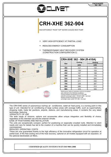
®PACKAGED362 - 904CRH-XHE 362-904HIGH EFFICIENCY "ROOF TOP" WATER COOLED HEAT PUMP• VERY HIGH EFFICIENCY AT PARTIAL LOAD• REDUCED ENERGY CONSUMPTION• THERMODYNAMIC HEAT RECOVERY SYSTEM(CONSTRUCTION CONFIGURATION C)CRH-XHE 362 - 904 (R-410A)SizeCooling[kW]Heating[kW]362 121 134402 136 153452 147 168464 162 179524 184 205604 211 232704 239 267804 285 312904 315 344Performance refers to operation at full re-circulationdata referred to the following conditions :Cooling Ambient temperature 27°C/19.5 WBexternal exchanger water = 30/35°C WB = wet bulbHeating ambient temperature 20°C DBexchanger water outlet 10°C DB = dry bulbThe CRH-XHE series of autonomous roof-top air conditioners, water-air heat pump, is a turning point in thistype of unit. Intended for air conditioning of large surface areas with average traffic, such as supermarkets,shopping malls, trade fair pavilions, airports, stations, and manufacturing areas, it contains the very latesttechnology, featuring:VERSATILITY OF USEThe wide range of versions, options and accessories allow unique integration and flexibility of choice,regardless of the intended use and the external climate.EASE OF POSITIONING AND INSTALLATIONThe units are exceptionally compact, perfect for positioning on especially crowded roofs. Attention to clientneeds and care for details has led to the creation of a machine than can be quickly installed and immediatelycommissioned.REDUCED OPERATING COSTSThese are now guaranteed thanks to the high efficiency of the innovative refrigeration circuit for operation atpartial load, of the free-cooling and of the heat recovery, optional on all models equipped with air expulsion, ofthe optional electrostatic air filters.BT08L005GB-01CERTIFIED QUALITY SYSTEM UNI EN ISO 9001:2008
BT08L005GB-01PACKAGED362 - 904GENERAL DESCRIPTIONMAIN FUNCTIONS AND APPLICATIONSThe CRH-XHE autonomous roof-top air conditioners are highefficiencywater-air heat pumps with completely automaticoperation. Based on user settings, the unit provides complete airtreatment through ventilation, filtering, cooling, heating, completeor partial addition of fresh air, possibility to control humidity. Thesemachines are extremely compact and resistant to atmosphericagents, suitable for outdoor installation on a flat roof, on a platformor on the ground. The distribution of treated air (to be handled bythe client) takes place via supply and return ducts and suitabledistribution devices such as air outlets or nozzles. They aretherefore perfect for air conditioning of large-volume rooms withaverage traffic, such as large commercial surfaces, trade fairpavilions, airports, stations, and production areas.APPLICATIONSVERSATILITY OF USEThe wide range of models and the possibility to choose theconstructive configurations make it possible to select the productthat is best suited to the needs of each installation and to integratethe unit into various architectonic contexts. The selection ofaccessories completes the possibility to customize the productaccording to the needs of the client.VERSATILE POSITIONING: ON FLAT ROOF, ONPLATFORM ON GROUNDEXTREME COMPACTNESSThe original layout of the sections that make up the machinesubstantially reduces its footprint, making it easier to position andleaving more space available for parking, additional equipmentrooms or other uses. This also reduces the time required for thepositioning of the ducts on the various sides of the unit, since itsgreat compactness allows its complete rotation (which is verydifficult with traditional units with in-line extension).APPLICATION EXAMPLESREDUCTION OF CONSUMPTION AND OPERATING COSTSThe roof-top units of the XHE series were created with theobjective of always operating at maximum energy savings throughan extremely intelligent and advanced control of power providedonly when it is needed, especially during frequent conditions ofoperation at partial load. The use of the free-cooling device and theadoption of thermodynamic recovery on the expelled air make itpossible to further reduce operating costs. Since ventilationrepresents one of the greatest factors of energy consumption,special attention has been given to the efficiency of the ventilationsystem through careful selection of components and limitations ofinternal pressure drops. The limitation of the emissions of carbondioxide and respect for the environment are guiding thoughts ofClivet which, through the implementation of modern technicalsolutions, pursues the reduction of energy consumption.EASY MAINTENANCEThe entire series is designed with highly reliable industrialcomponents that are easily accessible and available ifmaintenance is required. It is also equipped with self-diagnosis andsafety devices that ensure its proper operation while at the sametime protecting users.2
BT08L005GB-01GENERAL DESCRIPTION OF CONFIGURATIONS AVAILABLE IN CATALOGUEPACKAGED362 - 904The CRH-XHE range of air conditioners is highly customizable and is based on a standard model (version B), ona model with integrated expulsion (version C) and on a model with integrated expulsion and energy recovery onexpelled air (version C with recovery). Both configuration are capable of conditioning air flow rates with mixturesof return air and fresh air. The units are available with air flow in three modes: high, standard and reduced andcan be further customized with the choice of accessories (optional) especially designed to meet variousapplication needs.CB - PRINCIPLE OF OPERATION OF STANDARD UNIT (VERSION B)The standard constructional configuration, called version B, allows control of supply and return air flow and theintake of fresh air for required refreshing by means of a manually operated shutter.The version with optional setups is equipped with shutters with a servo-motor for constant adjustment of therefresh air mixture:- operation with a fixed percentage of refresh air with opening or closing of the shutter by means of an actuator(ON-OFF) which intervenes when ventilation is active (optional)- operation with variable percentage of refresh air with opening and closing of the shutters by means ofmodulating actuators driven by the signal of the air quality probe (optional)- operation with variable percentage of refresh air with opening and closing of the shutters by means ofmodulating actuators, which intervene when the fresh air conditions are such that they allow lowering of internalthermal loads simply by placing primary air in the room (free-cooling B) (optional).CONFIGURATION B STANDARD OR WITHSHUTTER ON-OFFCONFIGURATION B WITH FREECOOLING VERSION BSUPPLY +70%RETURN SUPPLY +70%RETURN-30%-MAN30%FRESH AIRAUTFRESH AIRCC - OPTIONAL VERSION WITH AIR EXPULSION AND FREE-COOLINGWhen the machine is in optional constructive configuration (called version C), it allows automatic management ofthe supply and return air flows, and the intake of fresh air for required refreshing. In addition, it is capable ofpartially or entirely expelling the return air by means of dedicated fans.The automatic adjustment of the shutters allows operation of the unit:- with full recirculation- with a mixture of re-circulation air and fresh air- with continuous adjustment of the flow rates of fresh and expelled air (modulating free-cooling);- with all fresh air and total expulsion of return air (total free-cooling).CONSTRUCTIONAL CONFIGURATION CEXHAUST AIRSUPPLY+-30%30%70%RETURNFRESH AIR3
BT08L005GB-01PACKAGED362 - 904FC - THERMAL FREE COOLING (construction configuration C)As soon as external conditions allow it, the unit is capable of automatically activating free-cooling mode, which, bykeeping the compressors off and drawing in suitably filtered fresh air, cools the served room. The fresh air flowcan be varied based on actual needs. This operating mode is especially useful in spring and autumn or with highambient loads. It allows substantial reduction of the unit's energy consumption and wear of the compressors.CONFIGURATION CODE(1)(2) (3)(4)(5)(6)(7)CRH - XHE C 452 M 200R100SMSRBSMSRCRMRRHMHR(1) CONSTRUCTIONAL CONFIGURATIONrecirculated/outside air mixing box (B)free cooling version with extract/recirculated/fresh air intake box (C)(2) SUPPLYStandard (S)(3) OUTLET STATIC PRESSURE VALUEOUTLET STATIC PRESSURE VALUE(4) RETURNStandard (S)(5) INTAKE STATIC PRESSURE VALUE(6) AIR FLOWStandard air flow (SM)Reduced air flow (RM)Air flow high (HM)(7) INTAKE AIR FLOWStandard air flow (SR)Reduced air flow (RR)Air flow high (HR)FILTRATIONStandard units are standard equipped with a suitable filtering sectioncomposed of pleated filters, class G4, with an ample surface. They are easilyaccessible for periodic maintenance.UPDATED ELECTRONIC CONTROLThe operation of the unit is fully automatic thanks to the Clivet Talk electronicadjustment system. This is a modular device, of automatic origins, with highspeed and reliability and control logic specifically designed for this type ofproduct. The user interface is easy to use. This allows better use of availableresources, extending the life cycle of the components and thus reducingmaintenance costs. With the micro-processor keypad, it is possible to performdaily/weekly programming of the set-point, as well as start-up or shutdown ofthe machine. The unit can also be connected to supervision systems usingclean contacts or by serial with the standards of communication mostcommonly available on the market.CONTROL LOGICS IN THE EVENT OF ALARM SIGNALMachine logics(1)Complete shutdown(2)Room kept depressurizedDescription Standard Version Vers. B withfree-cooling optionsupply fanreturn fanFresh air ShutterDischarge damperRecirculation shuttersupply fanreturn fanFresh air ShutterDischarge damperRecirculation shuttersupply fanOff Off Off- - OffOpen- --- - Off- - On- -- -- -ClosedClosedVersion COn On OnClosedClosedClosedClosedOpenClosedreturn fan- - Off(3)Room kept pressurized Fresh air ShutterOpenOpen OpenDischarge damper- -ClosedRecirculation shutter-ClosedClosedThe machine logic manages the signal from the smoke detector installed in the return section or by a fire detection unit, implementing one of the actions shown in the table which can be set as aparameter. If there is an alarm signal and according to the set logic, the compressors are always shut off. The roof-top units may not be used as smoke extractors.4
AVAILABLE POWERBT08L005GB-01OUTSIDE TEMPERATURE PROBEThe measurement of the temperature of outside air is an essentialparameter of heat adjustment. It takes place via a probe located in aspecial compartment that connects the external environment andthe return duct (always in negative pressure). Clivet has chosen thissolution to ensure correct measurement of temperature since theprobe is constantly in contact with a minimum flow of air. Onrequest, the temperature probe can be integrated with the optionalhumidity probe).INTAKE DUCTPACKAGED362 - 904FRESH AIROUTSIDE TEMPERATURE PROBEELECTRONIC EXPANSION VALVEThe electronic expansion valve is an essential component of the refrigerant circuit.It offers a number of advantages as compared to the traditional thermostatic valve.These include:- reduction of overheating temperature (greater efficiency of refrigerant circuit)- improved compressor working conditions (COP optimized)- reduction of pressure at condenser (less energy absorbed by compressors)- reduction of output temperature of the compressor- adaptation to all load conditions and transitories without causing swinging at partialloadsAll this aids in increasing the efficiency of the load for any thermal load condition and toextend the life cycle.LOW EFFICIENCYDANGER OF BREAKAGE OVERHEATINGHIGH EFFICIENCYOPTIMAL OPERATIONP = Provided Power VariationEEV= Electronic valveTEV = Thermostatic valveDEMAND LIMITLOW EFFICIENCYDANGER OF BREAKAGE PRESENCE OF LIQUIDThe Demand Limit function is a logic that controls the machine's resources dedicated to limiting the input powerfrom the electrical mains (for example when there are special agreements between the user and the operator ofthe electrical mains) or to selecting the thermal resources to be used based on special needs of the client. TheDemand Limit device can control and manage the available steps of thermal power by means of the receipt of anexternal analogue signal, 0-10V/4-20mA. The control logic does not act on the ventilation which is thereforealways ensured. The greater the input signal to the Demand Limit, the less the thermal power available for thesystem. In the extreme condition of pilot signal at 100%, the system can also shut off the last power step.[kW]AS THE DEMAND LIMIT SIGNAL INCREASES, THEPOWER STEPS ARE GRADUALLY DISABLED. WHEN THESIGNAL IS AT 100%, ALL AVAILABLE RESOURCES AREDISABLED.AUXILIARY ELECTRIC HEATING ELEMENTS60 2.5 5 7.5 10 [V]SIGNAL 0-10V DC5
BT08L005GB-01EERPACKAGED362 - 904PANELLINGThe need to improve access to the internal parts of the machine for theordinary maintenance and at the same time the need to give structuralstiffness and increase thermal insulation has brought to the adoption of"sandwich" type panels on all units. The roof and the structure of the airtreatment area are made with such panels with dual steel walls withpolyurethain foam and feature seal gaskets alongside the ledge. Thepanels are hinged and feature handles and closures with adjustableclamping.VERY HIGH EFFICIENCY AT PARTIAL LOADIn air conditioning projects, the choice of the unit is made based on the maximum load of the room to be served.In practice, over the course of the year these operating conditions are limited to short periods of time, whereasoperation at partial loads is the actual normal operating condition. The need to adapt the power provided to theload requested becomes essential in limiting energy consumption. This is why we have decided to couple twoscroll compressors of different power on a single refrigeration circuit, thus obtaining very high efficiency. Theelectronic control that the machine is equipped with divides compressor operation into three steps of power (1/3,2/3, 3/3). This limits the oscillation of the air temperature, and provides perfect adaptation to partial load, offeringsubstantial energy savings.9876% Working Time100%90%80%70%For 70% of thetime the load isunder 50%For 90% of thetime the load isunder 80%60%550%440%330%220%110%(1)(2) (3)0(1) (2) (3)0%
BT08L005GB-01PACKAGED362 - 904STANDARD UNIT SPECIFICATIONSCOMPRESSORScroll compressor complete with: overload thermal protection, high refrigerantdischarge temperature, rubber antivibration mounts, oil charge.A oil heater is automatically switched on at the compressor shut-down to preventoil dilution by the refrigerant.The compressors are connected in tandem on a single refrigerator circuit. Theyhave bi-phase equalization of the oil and are equipped with cut-off bibcocksA oil heater is automatically switched on at the compressor shut-down to preventoil dilution by the refrigerant.STRUCTUREThe basement is assembled with a painted galvanized steel frame. The internalstructure is made of “ALUZINK” bent galvanized steel . The alloy that protects theAluzink allow an excellent corrosion proofing thanks to the galvanic protectiontypical of the combination aluminium-zinc.PANELLINGPanels of the compressor panel in steel sheet metal, painted using polyesterpowders, colour RAL 9001 and covered on the inside with ashlared soundabsorbentmaterial.Sandwich panels in the air treatment section with dual walls in steel sheet metalwith polyurethane insulation (40 kg/m3), thickness of outer sheet metal 6/10 mmgalvanized and painted using polyester powders colour RAL 9001, polyurethanethickness with thermal conductivity coefficient 0.022W/mK, thickness of internalsheet metal 5/10 mm hot galvanized. The panel is also provided with a PVCprofile for thermal insulation and a EPDM rubber gasket that ensures the hermeticseal.All panelling can easily be removed to allow complete accessibility to internalcomponents.INTERNAL EXCHANGERDirect expansion finned exchanger, made from copper pipes in staggered rowsand mechanically expanded to the fin collars. The fins are made from aluminiumwith a corrugated surface and adequately distanced to ensure the maximum heatexchange efficiency.EXTERNAL EXCHANGERDirect expansion heat exchanger with braze welded stainless steel AISI 316plates and complete with external thermal/anti-condensation insulation, completewith water side differential pressure switch and water temperature control probe.FANSUPPLY FANCentrifugal fan with double intake, blades curved forward to achieve maximumperformance and silence. Statically and dynamically balanced as per standardsISO 1940 degree 6.3. Fastened to rubber anti-vibration devices. The screw, rotorand frame are made of galvanized sheet metal (semdzimir) the shaft is made ofC40 steel. Connection to electric motor with belt and pulleys.REFRIGERANT CIRCUITThe circuit is complete with:- refrigerant charge- sight glass with moisture indicator- high pressure switch- low pressure switch- filter dryer- electronic expansion valve- non-return valve- 4-way reverse cycle valve- liquid receiver- high pressure safety valve- low pressure safety valveFILTRATIONPleated filter for greater filtering surface, made up of galvanized plate frame withgalvanized and electric-welded protective mesh, and regenerable filtering mediamade from polyester fibre sized with synthetic resins. G4 efficiency according toCEN-EN 779 standard (Eurovent class EU4/5 - average efficiency 90.1% A-SHRAE 52-76 Atm). Self-extinguishing (resistance to fire class 1 - DIN 53438).For units up to size 452: additional filter G4 on the fresh air intake.- clean contacts for remote ON-OFF, cumulative alarm, fan status, compressorstatus, summer/winter mode- control keypad, including:display of the parameter indexdisplay of the set values and the error codesMENU button to jump to the main menuALARM button to access the alarm management functionsstatus button to display the status listunit operation or ventilation only selection buttonOn/Off and manual reset button for overload device activationUP and DOWN buttons to increase and decrease the valuesSelected function signal LEDCompressor timer / operation signal LEDRETURN FAN(Constructional configuration C)Centrifugal fan with double intake, blades curved forward to achieve maximumperformance and silence. Statically and dynamically balanced as per standardsISO 1940 degree 6.3. Fastened to rubber anti-vibration devices. The screw, rotorand frame are made of galvanized sheet metal (semdzimir) the shaft is made ofC40 steel. Connection to electric motor with belt and pulleys.External sectionHelical fans with shaped aluminium blades, directly coupled to the three-phaseelectric motor, with built-in thermal overload protection, minimum IP 54 construction.Mounted in aerodynamic housings to increase efficiency and minimise noiselevels, and fitted with safety grills.TESTUnit manufactured according to the ISO 9001 quality standards and subject tofunctional testing at the end of the production lineACCESSORIES- copper / copper evaporator coils- 2 rows hot water coil- modulating three-way valve- hot gas re-heating coil- Copper / copper hot gas re-heating coil- electrode boiler steam humidifier- water to waste evaporating wet-deck humidifier- Electric heaters.- Air quality sensor for CO2 p.p.m. control- Air quality sensor for CO2 and VOC p.p.m. control- bag filters section F7 class- High efficiency electrostatic filters additional section- differential pressure switch for dirty air filters- high and low pressure gauges- Active regeneration circuit on exhaust air- Plumbing assembly for loop with constant flow rate- Plumbing assembly for loop with variable flow rate- Plumbing assembly for system with disposable water- Antifreeze heater protection on the water side exchanger- Steel mesh filter on the water side (separately supplied accessories)- free-cooling with temperature comparison only (standard for version C)- free-cooling with independent comparison of temperature and absolute humidity- On/off motorized air outlet damper (only for B version)- Modulating air outlet damper (only for B version)- Disposal for inrush current reductionFans- Application with fabric ducts (only for C version)- high and low pressure gauges- smoke detector- phase monitor- power factor correction capacitors (cosfi > 0.9)- serial port RS485 with LONWORK protocol- serial port RS485 with MODBUS protocol- Remote control with remote microprocessor control (separately supplied accessories)TRAYCondensation collection basin in aluminium alloy 1050 H24 with anticondensationinsulation, welded and equipped with siphoned drain tubeELECTRICAL PANELthe electrical panel is situated inside the units and is accessed through a hingeddoor that is opened by a special keyThe Power Section includes:- main door lock isolator switch- compressor circuit breaker- compressor power supply remote control switch- fan motor thermal overload protection on air handlingcoil side- circuit breaker to protect auxiliary circuitmicroprocessor control section:- treated air temperature control- compressor overload protection and timer- centralised alarms with remote signalling- self-diagnosis system with immediate display of the error code- demand limit7
BT08L005GB-01PACKAGED362 - 904AIR FLOW: STANDARDGENERAL TECHNICAL SPECIFICATIONSSize 362 402 452 464 524 604 704 804 904COOLINGCooling capacity 1 kW 121,4 135,7 147,3 161,7 183,8 211,2 239,4 285,3 314,6Sensible capacity 1 kW 90,1 99,7 109,2 123,6 139,1 157,9 177 216,2 236,4Compressor power input 1 kW 22 24,8 28,1 28 33,2 37,9 43,8 50 56,7EER 1 5,53 5,47 5,25 5,77 5,53 5,57 5,47 5,7 5,55HEATINGHeat output 2 kW 134,2 152,6 168 178,7 205,1 231,8 266,7 311,6 344,2Compressor power input 2 kW 24,1 28,2 32 31,3 37,6 41,1 49,2 53,1 59,9COP 2 5,57 5,42 5,25 5,72 5,45 5,63 5,42 5,87 5,74COMPRESSORType of compressors 3 Scroll Scroll Scroll Scroll Scroll Scroll Scroll Scroll ScrollNo. of Compressors Nr 2 2 2 4 4 4 4 4 4Std Capacity control steps Nr 3 3 3 6 6 4 6 6 6Refrigerant circuits Nr 1 1 1 2 2 2 2 2 2AIR HANDLING SECTION FANS (OUTLET)Type of fans 4 CFG CFG CFG CFG CFG CFG CFG CFG CFGNumber of fans Nr 1 1 1 1 1 1 1 1 1Number of impellers Nr 2 2 2 2 2 2 2 2 2Air flow l/s 5555 6111 6666 8056 9028 10000 11111 12500 13888Installed unit power kW 7,5 7,5 9 9 11 15 18,5 18,5 22Max outside static pressure 5 Pa 300 210 210 240 210 330 300 330 270Max outside static pressure 6 Pa 570 570 570 570 570 510 570 570 570FANS (RETURN)Type of fans 7 CFG CFG CFG CFG CFG CFG CFG CFG CFGNumber of fans Nr 1 1 1 1 1 1 1 1 1Air flow l/s 4444 4888 5333 6444 7222 8000 8889 10000 11111Installed unit power kW 3 3 4 4 5,5 7,5 7,5 7,5 11Max outside static pressure 8 Pa 210 120 120 150 180 240 120 120 210Max outside static pressure 9 Pa 450 450 450 420 420 450 450 450 450EXTERNAL EXCHANGERWater flow rate (External Exchanger) l/s 6,9 7,7 8,4 9,1 10,4 11,9 13,5 16 17,7POWER SUPPLYStandard power supply V 400/3/50 400/3/50 400/3/50 400/3/50 400/3/50 400/3/50 400/3/50 400/3/50 400/3/50Performance refers to operation at full re-circulation(1) data referred to the following conditions :Ambient temperature 27°C/19.5 WBwater to internal exchanger 30/35°CWB = wet bulbEER referred only to compressors(2) data referred to the following conditions :ambient temperature 20°C DBexchanger water outlet 10°CDB = dry bulbCOP referred only to compressors(3) SCROLL = scroll compressor(4) CFG = centrifugal fan(5) with standard electric motor(6) with uprated electric motors(7) Constructional configuration CCFG = centrifugal fan(8) with standard electric motor(9) with uprated electric motors8
BT08L005GB-01PACKAGED362 - 904ELECTRICAL DATACONSTRUCTIONAL CONFIGURATION: MIXING BOX FOR RECYCLE /FRESH AIR (B)Size 362 402 452 464 524 604 704 804 904F.L.A. - FULL LOAD CURRENT AT MAX ADMISSIBLE CONDITIONSF.L.A. - Compressor 1 A 36,5 44,9 44,9 30,6 30,6 30,6 36,5 44,9 44,9F.L.A. - Compressor 2 A 30,6 30,6 36,5 15,2 22,6 30,6 30,6 30,6 36,5F.L.A. - Compressor 3 A - - - 30,6 30,6 30,6 36,5 44,9 44,9F.L.A. - Compressor 4 A - - - 15,2 22,6 30,6 30,6 30,6 36,5F.L.A. - Single supply fan 1 A 14,9 14,9 19 19 21 28,5 35 35 41F.L.A. - Total 2 A 67,6 76 81,9 92,1 106,9 122,9 134,7 151,5 163,3L.R.A. LOCKED ROTOR AMPERESL.R.A. - Compressor 1 A 225 272 272 173 173 173 225 272 272L.R.A. - Compressor 2 A 173 173 225 95 118 173 173 173 225L.R.A. - Compressor 3 A - - - 173 173 173 225 272 272L.R.A. - Compressor 4 A - - - 95 118 173 173 173 225L.R.A. - Single supply fan A 113,2 113,2 144,4 144,4 159,6 216,6 266 245 295,2F.L.I. FULL LOAD POWER INPUT AT MAX ADMISSIBLE CONDITIONF.L.I. - Compressor 1 kW 22,6 27,3 27,3 17 17 17 22,6 27,3 27,3F.L.I. - Compressor 2 kW 17 17 22,6 8,9 13,2 17 17 17 22,6F.L.I. - Compressor 3 kW - - - 17 17 17 22,6 27,3 27,3F.L.I. - Compressor 4 kW - - - 8,9 13,2 17 17 17 22,6F.L.I. - Single supply fan 3 kW 7,5 7,5 9 9 11 15 18,5 18,5 22F.L.I. - Total 4 kW 39,9 44,6 50,2 52,1 60,7 68,3 79,5 88,9 100,1power supply: 400/3/50 Hz +/-6%voltage unbalance: max 2 %Values not including accessories(1) n.d. = not definedThe input of the fan motors is shown in the performance tables of the fansThe installed motor must be determined taking into consideration the air flow rate and theusable static pressure(2) value including all standard components of the unitcontrol circuit includedThis data does not take into consideration the motors of the zone treatment fans nor theaccessoriesto obtain the overall F.L.A. value, add the total F.L.A. value to that of any accessories (seeelectrical data of accessories) and that of the motors of the treatment area fans (see table offan performance)(3) n.d. = not definedThe input of the fan motors is shown in the performance tables of the fansThe installed motor must be determined taking into consideration the air flow rate and theusable static pressure(4) value including all standard components of the unitcontrol circuit includedThis data does not take into consideration the motors of the zone treatment fans nor theaccessoriesto obtain the overall F.L.I. value, add the total F.L.I. value to that of any accessories (seeelectrical data of accessories) and that of the motors of the treatment area fans (see table offan performance)CONSTRUCTIONAL CONFIGURATION: FREE COOLING VERSION WITH EXTRACT/RECIRCULATED/FRESH AIR INTAKE BOX (C)ELECTRICAL DATASize 362 402 452 464 524 604 704 804 904F.L.A. - FULL LOAD CURRENT AT MAX ADMISSIBLE CONDITIONSF.L.A. - Compressor 1 A 36,5 44,9 44,9 30,6 30,6 30,6 36,5 44,9 44,9F.L.A. - Compressor 2 A 30,6 30,6 36,5 15,2 22,6 30,6 30,6 30,6 36,5F.L.A. - Compressor 3 A - - - 30,6 30,6 30,6 36,5 44,9 44,9F.L.A. - Compressor 4 A - - - 15,2 22,6 30,6 30,6 30,6 36,5F.L.A. - Single supply fan 1 A 14,9 14,9 19 19 21 28,5 35 35 41F.L.A. - Single Inlet fan 1 A 6,5 6,5 8,3 8,3 11,2 14,9 14,9 19 21F.L.A. - Total 2 A 67,6 76 81,9 92,1 106,9 122,9 134,7 151,5 163,3L.R.A. LOCKED ROTOR AMPERESL.R.A. - Compressor 1 A 225 272 272 173 173 173 225 272 272L.R.A. - Compressor 2 A 173 173 225 95 118 173 173 173 225L.R.A. - Compressor 3 A - - - 173 173 173 225 272 272L.R.A. - Compressor 4 A - - - 95 118 173 173 173 225L.R.A. - Single supply fan A 113,2 113,2 144,4 144,4 159,6 216,6 266 245 295,2L.R.A. - Single Intake fan A 49,4 49,4 63,1 63,1 85,1 113,2 113,2 144,4 151,2F.L.I. FULL LOAD POWER INPUT AT MAX ADMISSIBLE CONDITIONF.L.I. - Compressor 1 kW 22,6 27,3 27,3 17 17 17 22,6 27,3 27,3F.L.I. - Compressor 2 kW 17 17 22,6 8,9 13,2 17 17 17 22,6F.L.I. - Compressor 3 kW - - - 17 17 17 22,6 27,3 27,3F.L.I. - Compressor 4 kW - - - 8,9 13,2 17 17 17 22,6F.L.I. - Single supply fan 3 kW 7,5 7,5 9 9 11 15 18,5 18,5 22F.L.I. - Single Inlet fan 3 kW 3 3 4 4 5,5 7,5 7,5 9 11F.L.I. - Total 4 kW 39,9 44,6 50,2 52,1 60,7 68,3 79,5 88,9 100,1power supply: 400/3/50 Hz +/-6%voltage unbalance: max 2 %Values not including accessories(1) n.d. = not definedThe input of the fan motors is shown in the performance tables of the fansThe installed motor must be determined taking into consideration the air flow rate and theusable static pressure(2) value including all standard components of the unitcontrol circuit includedThis data does not take into consideration the motors of the zone treatment fans nor theaccessoriesto obtain the overall F.L.A. value, add the total F.L.A. value to that of any accessories (seeelectrical data of accessories) and that of the motors of the treatment area fans (see table offan performance)(3) n.d. = not definedThe input of the fan motors is shown in the performance tables of the fansThe installed motor must be determined taking into consideration the air flow rate and theusable static pressure(4) value including all standard components of the unitcontrol circuit includedThis data does not take into consideration the motors of the zone treatment fans nor theaccessoriesto obtain the overall F.L.I. value, add the total F.L.I. value to that of any accessories (seeelectrical data of accessories) and that of the motors of the treatment area fans (see table offan performance)9
BT08L005GB-01PACKAGED362 - 904ELECTRICAL INPUT OF OPTIONAL COMPONENTSTo obtain the electrical input of the unit including accessories, add the standard data in Electrical Data table tothose for the selected accessories.GRANDEZZE 362 402 452 464 524 604 704 804 904F.L.A. CORRENTE ASSORBITAF.L.A. EH20 - Resistenze elettriche di riscaldamento da 24 kWF.L.A. EH24 - Resistenze elettriche di riscaldamento da 36 kWF.L.A. EH28 - Resistenze elettriche di riscaldamento da 48 kWF.L.A. EH72 - Resistenze elettriche di riscaldamento da 72 kWF.L.A. EH33 - Resistenze elettriche di riscaldamento da 96 kWF.L.A. HSE8 - Umidificatore a vapore ad elettrodi immersi da 8 kg/hF.L.A. HSE9 - Umidificatore a vapore ad elettrodi immersi da 15 kg/hF.L.A. FES - Filtri elettrostastici ad alta efficienza classe H10F.L.I. POTENZA ASSORBITAF.L.I. EH20 - Resistenze elettriche di riscaldamento da 24 kWF.L.I. EH24 - Resistenze elettriche di riscaldamento da 36 kWF.L.I. EH28 - Resistenze elettriche di riscaldamento da 48 kWF.L.I. EH72 - Resistenze elettriche di riscaldamento da 72 kWF.L.I. EH33 - Resistenze elettriche di riscaldamento da 96 kWF.L.I. HSE8 - Umidificatore a vapore ad elettrodi immersi da 8 kg/hF.L.I. HSE9 - Umidificatore a vapore ad elettrodi immersi da 15 kg/hF.L.I. FES - Filtri elettrostastici ad alta efficienza classe H10A 34.6 34.6 34.6 - - - - - -A 52.0 52.0 52.0 52.0 52.0 52.0 52.0 - -A 69.4 69.4 69.4 69.4 69.4 69.4 69.4 69.4 69.4A - - - 104.0 104.0 104.0 104.0 104.0 104.0A - - - 138.6 138.6 138.6 138.6 138.6 138.6A 8.7 8.7 8.7 - - - - - -A 16.2 16.2 16.2 16.2 16.2 16.2 16.2 16.2 16.2A 2.2 2.2 2.2 2.2 2.2 2.2 2.2 2.2 2.2kW 24 24 24 - - - - - -kW 36 36 36 36 36 36 36 - -kW 48 48 48 48 48 48 48 48 48kW - - - 72 72 72 72 72 72kW - - - 96 96 96 96 96 96kW 6 6 6 - - - - - -kW 11.25 11.25 11.25 11.25 11.25 11.25 11.25 11.25 11.25kW 0.5 0.5 0.5 1 1 1 1 1.25 1.25CALCULATION OF BREAKAWAY CURRENT (M.I.C.)The calculation of the breakaway current (M.I.C.) is necessary in order to size the protection up the electrical linefrom the unit. Its value depends on the selected configuration and the components selected (motor sizes). TheM.I.C. is obtained by summing the maximum breakaway current (L.R.A.) of the largest compressor and the inputcurrent at the maximum admissible conditions (F.L.A.) of the remaining electrical components.M.I.C. = L.R.A.(C1) + F.L.A.(C2) + F.L.A.(C3) + F.L.A.(C4) + F.L.A.(Fan Intake) + F.L.A.(Fan Return)L.R.A. (C1) = breakaway current of the larger size compressor (Tandem 1).F.L.A. (C2) = input current of the smaller size compressor (Tandem 1).F.L.A. (C3) = input current of the larger size compressor (Tandem 2).F.L.A. (C4) = input current of the smaller size compressor (Tandem 2).F.L.A.(Fan Intake) = input current of supply fan.F.L.A.(Fan Return) = input current of return fan (only for version C).Example of calculation of the M.I.C. for units size 464 configuration C with standard supply fan (9 kW) and standard return fan (4 kW):M.I.C. = 173 + 15.2 + 30.6 + 15.2 + 9 + 4 = 247 ATANDEM 1 TANDEM 2C1 C2 C3 C410
SizeBT08L005GB-01To D.B. [°C]Ta W.B. [°C]PACKAGED362 - 904OPERATING LIMITS (COOLING)30252015105(2)10 15 20 25 30 35 40 45 50T H 2 O [°C](1)THE LIMITS ARE INDICATIVE AND HAVE BEEN CALCULATED CONSIDERING:- VALUES GENERAL AND NOT SPECIFICATIONS,- STANDARD AIR FLOW-RATE,- NON-CRITICAL POSITIONING AND CORRECT USE OF THE UNIT,- OPERATION AT FULL LOAD(-) DIFFERENCE BETWEEN INLET / OUTLET WATER TEMPERATURE = 5°CWITH UNIT OPERATING IN INTAKE OF OUTSIDE AIR CALCULATE THE TEMPERATU-RES OF MIXES WHICH ARE GENERATED FROM THE EXCHANGERS' INLET TO KNOWTHE LIMITS.TA = INTERNAL EXCHANGER INLET AIR TEMPERATURE W.B. (°C)WB = WET BULBTH20 = WATER LOOP TEMPERATURE (°C)(-) INTERNAL EXCHANGER WATER INLET(1) THE DASHED AREA REFERS TO THE FIELD OF UNITS OPERATIONSTANDARD(2) THE AREA WITH THE DOTTED OUTLINE IDENTIFIES THE FIELD OF OPERATION OFTHE UNITS WITH PLUMBING ASSEMBLY FOR A SYSTEM WITH DISPOSABLE WATER(OPTIONAL)OPERATING LIMITS (HEATING)302520151050-5-10(2) (1)(3)0 5 10 15 20 25 30 35 40T H 2 O [°C]THE LIMITS ARE INDICATIVE AND HAVE BEEN CALCULATED CONSIDERING:- VALUES GENERAL AND NOT SPECIFICATIONS,- STANDARD AIR FLOW-RATE,- NON-CRITICAL POSITIONING AND CORRECT USE OF THE UNIT,- OPERATION AT FULL LOAD(-) DIFFERENCE BETWEEN INLET / OUTLET WATER TEMPERATURE = 5°CWITH UNIT OPERATING IN INTAKE OF OUTSIDE AIR CALCULATE THE TEMPERATU-RES OF MIXES WHICH ARE GENERATED FROM THE EXCHANGERS' INLET TO KNOWTHE LIMITS.TO = TEMPERATURE OF AIR ENTERING THE INTERNAL EXCHANGER D.B.(°C)DB = DRY BULBTH20 = WATER LOOP TEMPERATURE (°C)(-) INTERNAL EXCHANGER WATER INLET(1) THE DASHED AREA REFERS TO THE FIELD OF UNITS OPERATIONSTANDARD(2) THE DASHED AREA INDICATES THE OPERATING RANGE WITH WATER WITHGLYCOL ADDED TO PREVENT FREEZING(3) THE AREA WITH THE DOTTED OUTLINE IDENTIFIES THE FIELD OF OPERATION OFTHE UNITS WITH PLUMBING ASSEMBLY FOR A SYSTEM WITH DISPOSABLE WATER(OPTIONAL)SOUND LEVELSAir flow: standardSound Power Level (dB)Octave band (Hz)SoundpressurelevelSoundpower level63 125 250 500 1000 2000 4000 8000 dB(A) dB(A)362 89 82 88 85 85 81 76 67 69 89402 90 83 89 86 85 82 76 64 70 89452 91 84 90 87 86 83 77 66 71 90464 99 95 98 88 84 75 70 67 72 92524 104 95 95 91 87 81 76 73 73 93604 104 95 95 91 87 81 76 73 73 93704 106 96 95 92 87 81 76 74 73 93804 105 98 98 91 90 83 77 76 74 95904 106 100 99 93 91 84 78 77 75 96the sound levels refer to the unit at full load, in the rated test conditions.The sound pressure level refers to a distance of 1m from the external surface ofthe units operating in an open field.standard 50 Pa static pressure(standard UNI EN ISO 3744)Please note that when the unit is installed in conditions other than nominal testconditions (e.g. near walls or obstacles in general), the sound levels may undergosubstantial variations.11
BT08L005GB-01PACKAGED362 - 904AIR FLOW: STANDARDSize 362 402 452 464 524 604 704 804 904Air flow l/s 5555 6111 6666 8056 9028 10000 11111 12500 13888COOLING PERFORMANCESizeTa(°C)DB/WBTEMPERATURE OF WATER LEAVING THE EXTERNAL HEAT EXCHANGER (°C) - TEMPERATURE DIFFERENTIAL 5°C25 30 35 40 45 50kWf kWe kWs kWf kWe kWs kWf kWe kWs kWf kWe kWs kWf kWe kWs kWf kWe kWs36240245246452422 / 1624 / 1726 / 1927 / 19,528 / 2130 / 2222 / 1624 / 1726 / 1927 / 19,528 / 2130 / 2222 / 1624 / 1726 / 1927 / 19,528 / 2130 / 2222 / 1624 / 1726 / 1927 / 19,528 / 2130 / 2222 / 1624 / 1726 / 1927 / 19,528 / 2130 / 2222 / 1624 / 17117,1 18,0 86,8 113,1 19,6 84,6 108,7 21,6 82,5 104,0 23,9 80,3 99,0 26,5 78,2 93,6 29,5 76,1120,7 18,2 92,3 116,7 19,8 90,1 112,3 21,7 87,9 107,4 24,0 85,7 102,2 26,6 83,4 96,7 29,5 81,2128,3 18,4 92,1 124,1 20,0 89,8 119,6 21,9 87,5 114,6 24,2 85,2 109,2 26,8 83,0 103,3 29,7 80,7130,2 18,5 94,7 126,1 20,0 92,4 121,5 22,0 90,1 116,5 24,2 87,9 111,0 26,8 85,6 105,0 29,8 83,3136,2 18,7 91,3 132,0 20,2 89,0 127,4 22,1 86,7 122,2 24,4 84,4 116,6 27,0 82,2 110,5 29,9 79,9140,3 18,8 95,9 136,1 20,3 93,6 131,4 22,2 91,3 126,2 24,5 89,1 120,5 27,1 86,8 114,3 30,0 84,5129,8 20,3 95,8 125,9 22,2 93,5 121,4 24,4 91,2 116,5 27,0 88,8 111,0 29,9 86,5 105,0 33,1 84,1133,9 20,4 102,0 130,0 22,3 99,6 125,4 24,5 97,2 120,2 27,1 94,8 114,5 30,0 92,4 108,1 33,2 90,1142,5 20,7 101,7 138,4 22,5 99,2 133,6 24,7 96,8 128,1 27,3 94,4 121,9 30,2 91,9 114,9 33,4 89,5144,7 20,8 104,6 140,5 22,6 102,1 135,7 24,8 99,7 130,1 27,3 97,2 123,8 30,2 94,8 116,8 33,4 92,4151,3 21,0 100,8 147,1 22,8 98,4 142,1 25,0 95,9 136,4 27,5 93,5 129,9 30,3 91,0 122,7 33,5 88,6155,9 21,1 105,9 151,6 22,9 103,5 146,6 25,1 101,1 140,8 27,6 98,6 134,2 30,4 96,2 126,9 33,6 93,8141,8 23,1 104,8 137,5 25,1 102,0 132,6 27,5 99,1 127,0 30,4 96,3 120,6 33,6 93,4 113,6 37,2 90,6146,0 23,2 111,6 141,7 25,2 108,7 136,6 27,7 105,8 130,9 30,5 102,9 124,5 33,7 100,0 117,3 37,4 97,1155,2 23,4 111,9 150,5 25,5 108,9 145,1 28,0 106,0 139,1 30,8 103,0 132,5 34,0 100,1 125,2 37,6 97,2157,7 23,5 115,1 152,8 25,6 112,2 147,3 28,1 109,2 141,2 30,9 106,3 134,5 34,1 103,3 127,3 37,7 100,4165,6 23,7 110,5 160,0 25,8 107,6 154,0 28,3 104,7 147,7 31,1 101,7 140,9 34,3 98,8 133,8 37,9 95,9171,1 23,8 114,6 165,0 26,0 111,7 158,7 28,5 108,9 152,1 31,3 106,0 145,4 34,5 103,2 138,4 38,0 100,3155,0 22,7 117,1 150,3 24,9 114,7 145,0 27,6 112,3 139,2 30,7 109,9 133,0 34,2 107,5 126,1 38,3 105,1159,9 22,9 124,7 155,1 25,0 122,2 149,7 27,7 119,8 143,7 30,8 117,4 137,1 34,3 114,9 129,9 38,3 112,5170,0 23,2 124,4 165,0 25,3 121,9 159,3 27,9 119,4 153,0 30,9 117,0 146,0 34,4 114,5 138,4 38,4 112,0172,7 23,3 128,5 167,5 25,4 126,0 161,7 28,0 123,5 155,4 31,0 121,1 148,4 34,5 118,6 140,8 38,4 116,1180,6 23,6 125,1 175,1 25,7 122,6 169,2 28,2 120,1 162,7 31,1 117,6 155,8 34,6 115,1 148,4 38,4 112,6186,1 23,8 134,4 180,3 25,8 131,9 174,2 28,3 129,4 167,7 31,2 126,8 160,9 34,6 124,3 153,8 38,5 121,8176,3 27,0 131,3 170,8 29,7 128,3 164,7 32,8 125,4 157,9 36,4 122,4 150,5 40,5 119,4 142,4 45,1 116,5181,5 27,2 140,5 176,1 29,8 137,5 170,0 32,9 134,5 163,1 36,5 131,5 155,5 40,6 128,5 147,1 45,1 125,5192,6 27,6 141,0 187,2 30,1 137,9 180,9 33,1 134,9 173,7 36,7 131,8 165,6 40,7 128,7 156,6 45,3 125,6195,6 27,7 145,3 190,1 30,2 142,2 183,8 33,2 139,1 176,4 36,7 136,1 168,2 40,8 133,0 159,0 45,3 129,9204,8 28,0 138,5 199,1 30,5 135,3 192,4 33,4 132,2 184,7 36,9 129,0 176,0 40,9 125,9 166,2 45,4 122,7211,2 28,2 142,8 205,3 30,6 139,6 198,4 33,6 136,4 190,4 37,0 133,2 181,3 41,0 130,0 171,1 45,6 126,8202,6 31,0 151,9 196,6 33,9 148,5 189,7 37,3 145,1 181,9 41,4 141,7 173,3 46,2 138,3 163,7 51,5 134,9208,8 31,3 161,4 202,7 34,1 158,0 195,7 37,5 154,6 187,7 41,6 151,1 178,8 46,3 147,7 169,0 51,6 144,260470426 / 1927 / 19,528 / 2130 / 2222 / 1624 / 1726 / 1927 / 19,528 / 21221,6 31,8 160,3 215,3 34,5 156,8 208,0 37,8 153,2 199,8 41,8 149,7 190,6 46,5 146,2 180,5 51,7 142,6224,9 31,9 165,0 218,5 34,6 161,4 211,2 37,9 157,9 202,9 41,9 154,3 193,7 46,5 150,8 183,6 51,8 147,2235,1 32,3 159,5 228,4 35,0 155,9 220,9 38,2 152,2 212,5 42,1 148,6 203,3 46,6 145,0 193,2 51,8 141,3242,1 32,6 169,4 235,2 35,2 165,7 227,5 38,4 162,0 219,0 42,2 158,4 209,9 46,7 154,7 200,0 51,8 151,0229,4 36,0 170,6 222,2 39,2 166,3 214,1 43,1 162,0 205,1 47,6 157,7 195,2 52,9 153,4 184,4 58,8 149,0236,7 36,2 181,6 229,4 39,4 177,2 221,2 43,3 172,7 211,9 47,8 168,3 201,7 53,1 163,9 190,5 59,0 159,5251,9 36,7 180,9 244,3 39,8 176,4 235,7 43,7 171,8 226,1 48,2 167,3 215,3 53,4 162,7 203,5 59,4 158,1255,8 36,8 186,1 248,1 40,0 181,6 239,4 43,8 177,0 229,7 48,3 172,4 218,9 53,5 167,8 207,0 59,5 163,3267,9 37,2 179,8 259,7 40,3 175,2 250,6 44,1 170,6 240,6 48,6 166,1 229,8 53,8 161,5 218,0 59,8 156,930 / 22276,2 37,5 189,6 267,6 40,6 185,1 258,2 44,3 180,5 248,1 48,8 176,0 237,3 54,0 171,4 225,8 60,0 166,9Performance refers to operation at full re-circulationTa = input air temperature at treatment (°C)DB = dry bulbWB = wet bulbkWf = Cooling capacity in kWkWs = sensible cooling capacity (kW)kWe = Compressor power input in kWthe cooling capacities have not accounted for the heat dissipation of the centrifugal fan motors.12
BT08L005GB-01PACKAGED362 - 904AIR FLOW: STANDARDCOOLING PERFORMANCESizeTa(°C)DB/WBTEMPERATURE OF WATER LEAVING THE EXTERNAL HEAT EXCHANGER (°C) - TEMPERATURE DIFFERENTIAL 5°C25 30 35 40 45 50kWf kWe kWs kWf kWe kWs kWf kWe kWs kWf kWe kWs kWf kWe kWs kWf kWe kWs80490422 / 1624 / 1726 / 1927 / 19,528 / 2130 / 2222 / 1624 / 1726 / 1927 / 19,528 / 2130 / 22274,8 41,0 204,2 265,8 44,8 199,6 255,9 49,2 195,0 245,1 54,3 190,4 233,5 60,0 185,8 220,9 66,4 181,1283,3 41,3 218,5 274,2 45,0 213,9 264,0 49,4 209,4 252,7 54,5 204,8 240,4 60,2 200,3 227,0 66,7 195,7301,1 41,9 219,0 291,6 45,5 214,4 280,9 49,9 209,7 268,9 54,9 205,1 255,6 60,7 200,4 241,1 67,0 195,8305,6 42,0 225,7 296,1 45,7 220,9 285,3 50,0 216,2 273,2 55,1 211,5 259,8 60,8 206,8 245,0 67,1 202,0319,8 42,5 215,3 310,0 46,1 210,3 299,0 50,5 205,2 286,6 55,4 200,1 272,9 61,1 195,1 258,0 67,3 190,0329,5 42,8 222,6 319,6 46,5 217,2 308,4 50,8 211,8 296,0 55,7 206,4 282,4 61,2 201,0 267,5 67,4 195,6302,4 46,6 226,5 292,6 50,7 220,6 281,5 55,6 214,7 269,0 61,3 208,7 255,2 67,7 202,8 240,0 74,9 196,9312,3 46,9 241,2 302,1 51,0 235,2 290,6 55,9 229,2 277,7 61,6 223,1 263,4 68,0 217,1 247,8 75,2 211,0332,4 47,4 241,6 321,8 51,6 235,4 309,7 56,5 229,2 296,1 62,2 223,0 281,1 68,6 216,8 264,6 75,7 210,6337,6 47,6 248,9 326,8 51,8 242,6 314,6 56,7 236,4 300,9 62,3 230,2 285,7 68,7 224,0 269,0 75,9 217,7353,2 48,0 238,8 342,2 52,2 232,6 329,7 57,2 226,3 315,7 62,8 220,1 300,1 69,2 213,8 283,0 76,3 207,6363,8 48,3 249,0 352,8 52,6 242,7 340,1 57,5 236,5 325,9 63,2 230,3 310,1 69,6 224,1 292,8 76,7 217,8Performance refers to operation at full re-circulationTa = input air temperature at treatment (°C)DB = dry bulbWB = wet bulbkWf = Cooling capacity in kWkWs = sensible cooling capacity (kW)kWe = Compressor power input in kWthe cooling capacities have not accounted for the heat dissipation of the centrifugal fan motors.13
BT08L005GB-01PACKAGED362 - 904AIR FLOW: STANDARDSize 362 402 452 464 524 604 704 804 904Air flow l/s 5555 6111 6666 8056 9028 10000 11111 12500 13888HEATING PERFORMANCETEMPERATURE OF WATER LEAVING THE EXTERNAL HEAT EXCHANGER (°C) - TEMPERATURE DIF-Size Ta (°C)6 8 10 12 14 16kWt kWe kWt kWe kWt kWe kWt kWe kWt kWe kWt kWe3624024524645241015181920212510151819202125101518192021251015181920212510151819202125128,1 19,1 134,4 19,7 140,8 20,2 147,3 20,7 153,9 21,3 160,5 21,9125,3 20,9 131,3 21,4 137,5 22,0 143,8 22,6 150,1 23,2 156,6 23,8123,6 22,1 129,5 22,7 135,5 23,2 141,7 23,8 148,0 24,4 154,4 25,1123,0 22,5 128,9 23,1 134,9 23,7 141,0 24,3 147,3 24,9 153,7 25,5122,5 22,9 128,3 23,5 134,2 24,1 140,3 24,7 146,6 25,3 153,0 26,0121,9 23,4 127,7 24,0 133,6 24,5 139,7 25,2 145,9 25,8 152,3 26,4119,7 25,2 125,3 25,8 131,1 26,4 137,1 27,1 143,3 27,7 149,6 28,4145,8 22,3 152,9 22,9 160,2 23,6 167,5 24,2 174,9 24,9 182,4 25,6142,7 24,4 149,3 25,1 156,2 25,7 163,4 26,4 170,8 27,2 178,4 27,9140,8 25,8 147,3 26,5 154,0 27,2 161,0 27,9 168,3 28,6 175,9 29,3140,2 26,3 146,6 27,0 153,3 27,7 160,3 28,4 167,5 29,1 175,0 29,8139,6 26,8 146,0 27,5 152,6 28,2 159,5 28,9 166,7 29,6 174,1 30,3139,0 27,3 145,4 28,0 152,0 28,7 158,8 29,4 165,9 30,1 173,2 30,8136,6 29,5 143,0 30,2 149,4 30,8 156,0 31,5 162,7 32,2 169,5 32,9160,8 25,5 168,6 26,2 176,5 26,9 184,6 27,7 192,8 28,5 201,1 29,4157,0 27,8 164,4 28,5 172,0 29,3 179,9 30,2 188,1 31,1 196,6 32,0154,9 29,3 162,1 30,1 169,5 30,9 177,3 31,8 185,4 32,7 193,7 33,6154,2 29,9 161,3 30,6 168,7 31,5 176,5 32,3 184,5 33,2 192,7 34,2153,5 30,4 160,6 31,2 168,0 32,0 175,6 32,9 183,5 33,8 191,8 34,7152,8 31,0 159,9 31,8 167,2 32,6 174,8 33,5 182,6 34,4 190,8 35,3150,2 33,3 157,2 34,1 164,3 35,0 171,6 35,8 179,0 36,7 186,7 37,6169,7 24,5 178,0 25,1 186,5 25,8 195,2 26,5 204,1 27,2 213,2 28,0166,0 26,9 174,4 27,6 182,9 28,4 191,5 29,1 200,1 29,8 208,9 30,6164,1 28,6 172,2 29,3 180,4 30,1 188,8 30,8 197,3 31,5 205,9 32,3163,5 29,2 171,5 29,9 179,6 30,6 187,9 31,4 196,3 32,1 204,9 32,9163,0 29,8 170,7 30,5 178,7 31,3 186,9 32,0 195,3 32,7 203,9 33,5162,5 30,5 170,0 31,2 177,8 31,9 185,9 32,6 194,2 33,3 202,8 34,1160,9 33,2 167,2 33,8 174,1 34,5 181,5 35,2 189,6 35,9 198,2 36,7195,3 29,6 204,9 30,4 214,6 31,2 224,5 32,0 234,5 32,9 244,7 33,7191,2 32,6 200,5 33,4 209,9 34,2 219,6 35,1 229,5 35,9 239,6 36,8189,1 34,6 198,0 35,4 207,1 36,2 216,5 37,1 226,1 37,9 236,1 38,8188,5 35,3 197,1 36,1 206,1 36,9 215,4 37,8 225,0 38,6 234,9 39,5187,9 36,0 196,3 36,8 205,1 37,6 214,3 38,5 223,8 39,3 233,6 40,2187,3 36,8 195,5 37,5 204,1 38,3 213,1 39,2 222,5 40,1 232,3 41,0185,2 40,0 192,4 40,6 200,2 41,4 208,4 42,2 217,2 43,1 226,6 44,060410151819202125220,1 32,4 230,9 33,3 241,8 34,1 252,9 35,1 264,1 36,0 275,4 36,9216,1 35,6 226,5 36,5 236,9 37,4 247,6 38,3 258,3 39,2 269,2 40,2213,7 37,8 223,7 38,7 233,9 39,6 244,3 40,5 254,9 41,4 265,6 42,4212,8 38,5 222,7 39,4 232,8 40,3 243,2 41,3 253,7 42,2 264,5 43,1212,0 39,3 221,8 40,2 231,8 41,1 242,1 42,1 252,6 43,0 263,4 43,9211,1 40,1 220,8 41,0 230,7 41,9 240,9 42,9 251,5 43,8 262,3 44,7207,7 43,5 216,7 44,5 226,3 45,4 236,4 46,4 247,0 47,3 258,1 48,2Performance refers to operation at full re-circulationTa = input air temperature at treatment (°C)DB = dry bulbkWt = Heating capacity (kW)kWe = Compressor power input in kWnot all thermal yields take into account the heat dissipated by the fan motors14
BT08L005GB-01PACKAGED362 - 904AIR FLOW: STANDARDHEATING PERFORMANCETEMPERATURE OF WATER LEAVING THE EXTERNAL HEAT EXCHANGER (°C) - TEMPERATURE DIF-Size Ta (°C)6 8 10 12 14 16kWt kWe kWt kWe kWt kWe kWt kWe kWt kWe kWt kWe704804904101518192021251015181920212510151819202125254,6 39,0 267,1 40,0 279,8 41,1 292,6 42,2 305,6 43,4 318,7 44,6249,0 42,6 260,9 43,7 273,2 44,9 285,8 46,1 298,8 47,4 312,2 48,7245,7 45,0 257,3 46,2 269,3 47,4 281,8 48,7 294,7 50,0 308,0 51,4244,6 45,9 256,1 47,1 268,0 48,3 280,4 49,6 293,3 50,9 306,6 52,3243,5 46,8 254,9 47,9 266,7 49,2 279,0 50,5 291,9 51,8 305,2 53,2242,4 47,7 253,7 48,9 265,4 50,1 277,7 51,4 290,5 52,8 303,7 54,2237,9 51,5 248,9 52,7 260,4 54,0 272,3 55,3 284,8 56,8 297,7 58,2296,5 42,3 311,2 43,4 326,3 44,5 341,7 45,7 357,5 46,9 373,6 48,2290,1 46,2 304,4 47,3 319,0 48,5 333,7 49,7 348,7 51,0 363,9 52,3286,4 48,8 300,3 50,0 314,5 51,2 328,9 52,4 343,5 53,7 358,4 55,0285,2 49,7 299,0 50,9 313,0 52,1 327,3 53,4 341,8 54,6 356,6 55,9284,0 50,7 297,6 51,9 311,5 53,1 325,7 54,3 340,2 55,6 354,9 56,9282,8 51,6 296,2 52,8 310,0 54,0 324,1 55,3 338,5 56,5 353,2 57,8278,1 55,7 290,8 56,9 304,0 58,2 317,7 59,4 331,9 60,6 346,7 61,8328,8 48,0 345,1 49,2 361,7 50,4 378,9 51,8 396,4 53,2 414,4 54,7321,1 52,2 336,9 53,5 353,0 54,9 369,5 56,3 386,3 57,8 403,5 59,4316,5 55,1 332,0 56,5 347,7 57,9 363,8 59,3 380,3 60,9 397,1 62,5315,0 56,1 330,3 57,5 346,0 58,9 362,0 60,4 378,3 61,9 394,9 63,5313,5 57,1 328,7 58,5 344,2 59,9 360,1 61,4 376,3 63,0 392,8 64,6312,1 58,2 327,1 59,6 342,5 61,0 358,2 62,5 374,3 64,1 390,8 65,7306,3 62,6 320,6 64,1 335,5 65,5 350,7 67,1 366,4 68,6 382,6 70,2Performance refers to operation at full re-circulationTa = input air temperature at treatment (°C)DB = dry bulbkWt = Heating capacity (kW)kWe = Compressor power input in kWnot all thermal yields take into account the heat dissipated by the fan motors15
BT08L005GB-01PACKAGED362 - 904AIR FLOW: REDUCEDSize 362 402 452 464 524 604 704 804 904Air flow l/s 4444 4888 5333 6389 7222 8056 8889 10000 11111COOLING PERFORMANCESizeTa(°C)DB/WBTEMPERATURE OF WATER LEAVING THE EXTERNAL HEAT EXCHANGER (°C) - TEMPERATURE DIFFERENTIAL 5°C25 30 35 40 45 50kWf kWe kWs kWf kWe kWs kWf kWe kWs kWf kWe kWs kWf kWe kWs kWf kWe kWs36240245246452424 / 1726 / 1927 / 19,528 / 2130 / 2232 / 23,524 / 1726 / 1927 / 19,528 / 2130 / 2232 / 23,524 / 1726 / 1927 / 19,528 / 2130 / 2232 / 23,524 / 1726 / 1927 / 19,528 / 2130 / 2232 / 23,524 / 1726 / 1927 / 19,528 / 2130 / 2232 / 23,524 / 1726 / 19114,4 18,0 83,8 111,2 19,6 81,6 107,5 21,5 79,4 103,2 23,8 77,2 98,3 26,4 75,0 92,9 29,4 72,9122,0 18,2 83,3 118,3 19,8 81,0 114,1 21,7 78,8 109,6 24,0 76,5 104,6 26,6 74,3 99,3 29,6 72,0123,9 18,3 85,4 120,1 19,9 83,2 115,8 21,8 80,9 111,2 24,1 78,7 106,3 26,7 76,4 101,0 29,7 74,1129,8 18,5 83,3 125,6 20,1 81,1 121,2 22,0 78,8 116,5 24,2 76,5 111,5 26,8 74,3 106,2 29,8 72,0133,7 18,6 88,3 129,4 20,2 86,1 124,9 22,1 83,9 120,1 24,4 81,6 115,1 26,9 79,4 109,8 29,9 77,2139,7 18,8 92,4 135,3 20,4 90,2 130,7 22,3 88,0 125,8 24,5 85,8 120,7 27,1 83,7 115,4 30,0 81,5127,0 20,2 93,7 123,8 22,1 91,6 119,8 24,3 89,4 115,2 26,9 87,2 109,8 29,8 85,1 103,6 33,2 82,9135,6 20,5 93,5 131,7 22,3 91,3 127,2 24,6 89,2 122,2 27,1 87,0 116,6 30,0 84,8 110,4 33,3 82,7137,7 20,6 95,9 133,7 22,4 93,7 129,1 24,6 91,5 124,0 27,2 89,4 118,4 30,1 87,2 112,2 33,4 85,0144,2 20,8 91,4 139,9 22,6 89,2 135,1 24,8 86,9 129,8 27,4 84,7 124,1 30,2 82,4 117,9 33,5 80,2148,6 20,9 94,8 144,1 22,8 92,5 139,2 24,9 90,2 133,8 27,5 87,8 128,1 30,3 85,5 121,8 33,5 83,2155,1 21,1 93,0 150,6 23,0 90,5 145,6 25,1 88,0 140,2 27,6 85,5 134,3 30,5 82,9 128,1 33,6 80,4138,6 23,0 101,2 133,9 25,0 98,4 129,0 27,5 95,6 123,8 30,3 92,7 118,3 33,6 89,9 112,6 37,2 87,1148,0 23,2 100,7 143,3 25,3 97,9 138,1 27,8 95,2 132,6 30,6 92,4 126,6 33,8 89,6 120,2 37,4 86,9150,4 23,3 103,2 145,6 25,4 100,5 140,4 27,9 97,7 134,8 30,7 95,0 128,7 33,9 92,3 122,2 37,5 89,5157,8 23,5 100,4 152,8 25,6 97,9 147,4 28,1 95,3 141,5 30,9 92,8 135,2 34,1 90,2 128,5 37,7 87,7162,8 23,6 106,1 157,6 25,7 103,7 152,1 28,2 101,3 146,1 31,1 98,9 139,7 34,3 96,6 132,9 37,8 94,2170,5 23,8 109,9 165,0 25,9 107,9 159,1 28,4 105,9 153,0 31,3 103,9 146,6 34,5 101,8 139,8 38,0 99,8152,4 22,6 113,2 147,9 24,9 110,6 143,0 27,5 108,0 137,5 30,6 105,4 131,4 34,2 102,8 124,9 38,3 100,2162,1 23,0 112,7 157,5 25,1 110,1 152,3 27,7 107,5 146,5 30,8 104,9 140,0 34,3 102,3 132,9 38,3 99,7164,6 23,0 115,7 160,0 25,2 113,1 154,7 27,8 110,5 148,8 30,9 107,9 142,2 34,4 105,4 135,0 38,3 102,8172,5 23,3 111,8 167,6 25,4 109,3 162,1 28,0 106,8 155,9 31,0 104,2 149,1 34,4 101,7 141,6 38,4 99,2177,9 23,5 117,6 172,9 25,6 115,1 167,2 28,1 112,6 160,8 31,1 110,1 153,8 34,5 107,6 146,2 38,4 105,1186,4 23,8 119,6 181,0 25,8 117,2 174,9 28,3 114,8 168,3 31,2 112,4 161,1 34,5 110,0 153,4 38,4 107,6172,9 27,0 127,8 168,3 29,6 124,7 162,7 32,7 121,6 156,4 36,3 118,5 149,2 40,5 115,4 141,2 45,1 112,3183,8 27,3 126,8 179,2 29,9 123,6 173,6 33,0 120,5 167,0 36,5 117,4 159,3 40,6 114,3 150,6 45,2 111,1186,6 27,4 130,0 182,0 30,0 126,9 176,4 33,0 123,8 169,7 36,6 120,6 161,9 40,7 117,5 153,0 45,2 114,4195,4 27,7 126,3 190,7 30,2 123,3 184,8 33,2 120,3 177,8 36,7 117,3 169,6 40,8 114,3 160,4 45,3 111,3201,5 27,9 133,5 196,6 30,4 130,6 190,5 33,3 127,7 183,2 36,8 124,8 174,9 40,9 122,0 165,4 45,4 119,1211,1 28,2 138,7 205,6 30,6 136,1 199,1 33,5 133,5 191,5 37,0 130,9 182,8 41,0 128,3 173,1 45,6 125,6198,9 31,0 147,6 193,5 33,8 144,2 187,2 37,2 140,7 180,0 41,3 137,2 172,0 46,0 133,8 163,0 51,4 130,3212,0 31,4 146,7 206,1 34,2 143,2 199,3 37,6 139,6 191,7 41,6 136,1 183,2 46,3 132,6 173,8 51,6 129,060470427 / 19,528 / 2130 / 2232 / 23,524 / 1726 / 1927 / 19,528 / 2130 / 2232 / 23,5215,3 31,6 150,5 209,3 34,3 147,0 202,4 37,7 143,4 194,7 41,7 139,9 186,1 46,3 136,4 176,7 51,6 132,8225,6 32,0 145,7 219,0 34,6 142,3 211,8 38,0 138,8 203,7 41,9 135,4 195,0 46,5 132,0 185,6 51,7 128,5232,7 32,3 153,4 225,7 34,9 150,1 218,1 38,2 146,7 209,9 42,1 143,4 201,2 46,6 140,1 191,8 51,7 136,8243,5 32,7 157,3 235,9 35,3 154,2 227,8 38,5 151,1 219,4 42,3 148,0 210,7 46,7 144,9 201,6 51,8 141,9224,9 35,9 165,4 218,6 39,1 161,0 211,3 42,9 156,7 202,9 47,5 152,3 193,5 52,8 148,0 183,1 58,7 143,6239,1 36,3 164,9 232,1 39,5 160,5 224,2 43,4 156,0 215,5 48,0 151,5 205,9 53,2 147,0 195,5 59,1 142,5242,8 36,4 169,3 235,6 39,6 164,8 227,6 43,5 160,3 218,8 48,1 155,8 209,2 53,3 151,4 198,8 59,2 146,9254,6 36,8 164,4 246,7 40,0 159,9 238,3 43,8 155,5 229,2 48,4 151,1 219,5 53,6 146,7 209,2 59,5 142,3262,9 37,1 173,4 254,5 40,2 169,1 245,7 44,1 164,8 236,4 48,6 160,5 226,7 53,8 156,2 216,5 59,7 151,9275,9 37,5 178,2 266,8 40,6 174,2 257,4 44,4 170,2 247,9 48,9 166,1 238,0 54,1 162,1 228,0 59,9 158,116Performance refers to operation at full re-circulationTa = input air temperature at treatment (°C)DB = dry bulbWB = wet bulbkWf = Cooling capacity in kWkWs = sensible cooling capacity (kW)kWe = Compressor power input in kWthe cooling capacities have not accounted for the heat dissipation of the centrifugal fan motors.
BT08L005GB-01PACKAGED362 - 904AIR FLOW: REDUCEDCOOLING PERFORMANCESizeTa(°C)DB/WBTEMPERATURE OF WATER LEAVING THE EXTERNAL HEAT EXCHANGER (°C) - TEMPERATURE DIFFERENTIAL 5°C25 30 35 40 45 50kWf kWe kWs kWf kWe kWs kWf kWe kWs kWf kWe kWs kWf kWe kWs kWf kWe kWs80490424 / 1726 / 1927 / 19,528 / 2130 / 2232 / 23,524 / 1726 / 1927 / 19,528 / 2130 / 2232 / 23,5268,9 40,9 197,8 261,2 44,6 192,9 252,4 49,0 187,9 242,4 54,1 183,0 231,2 59,9 178,0 218,9 66,4 173,0286,6 41,4 197,0 278,6 45,1 191,9 269,1 49,5 186,8 258,2 54,6 181,7 245,8 60,4 176,6 232,0 66,8 171,5291,1 41,6 202,1 283,0 45,3 197,0 273,4 49,6 191,9 262,3 54,7 186,8 249,7 60,5 181,7 235,7 66,9 176,6304,8 42,0 195,8 296,4 45,7 190,7 286,5 50,0 185,7 275,0 55,1 180,6 262,0 60,8 175,6 247,5 67,2 170,5314,2 42,3 205,7 305,6 46,0 200,8 295,5 50,3 195,8 283,9 55,3 190,9 270,7 60,9 185,9 256,1 67,3 180,9328,5 42,8 209,6 319,6 46,4 204,9 309,3 50,7 200,2 297,6 55,6 195,5 284,5 61,2 190,8 270,1 67,4 186,0296,3 46,5 219,3 286,7 50,6 213,3 276,2 55,5 207,2 264,6 61,2 201,2 252,1 67,6 195,1 238,5 74,8 189,1315,5 47,0 219,7 305,6 51,2 213,5 294,7 56,1 207,3 282,5 61,8 201,1 269,1 68,2 194,9 254,6 75,4 188,7320,4 47,1 225,4 310,5 51,4 219,2 299,3 56,3 213,0 287,0 62,0 206,8 273,5 68,4 200,5 258,8 75,5 194,3335,6 47,6 217,1 325,1 51,8 210,9 313,5 56,8 204,7 300,7 62,5 198,4 286,9 68,8 192,2 272,1 75,9 186,0346,1 47,9 224,6 335,0 52,1 218,4 323,0 57,1 212,2 310,0 62,8 206,0 296,2 69,2 199,8 281,3 76,2 193,7362,3 48,3 219,6 350,1 52,6 213,6 337,4 57,6 207,5 324,2 63,3 201,4 310,3 69,7 195,3 295,9 76,7 189,2Performance refers to operation at full re-circulationTa = input air temperature at treatment (°C)DB = dry bulbWB = wet bulbkWf = Cooling capacity in kWkWs = sensible cooling capacity (kW)kWe = Compressor power input in kWthe cooling capacities have not accounted for the heat dissipation of the centrifugal fan motors.17
BT08L005GB-01PACKAGED362 - 904AIR FLOW: REDUCEDSize 362 402 452 464 524 604 704 804 904Air flow l/s 4444 4888 5333 6389 7222 8056 8889 10000 11111HEATING PERFORMANCETEMPERATURE OF WATER LEAVING THE EXTERNAL HEAT EXCHANGER (°C) - TEMPERATURE DIF-Size Ta (°C)6 8 10 12 14 16kWt kWe kWt kWe kWt kWe kWt kWe kWt kWe kWt kWe362402452464524101518192021251015181920212510151819202125101518192021251015181920125,4 20,5 131,7 21,1 137,9 21,7 144,2 22,4 150,5 23,1 156,9 23,8122,9 22,5 128,8 23,1 134,7 23,8 140,8 24,5 147,0 25,2 153,2 25,9121,3 23,8 127,0 24,4 132,9 25,1 138,8 25,8 145,0 26,5 151,2 27,3120,8 24,2 126,4 24,9 132,2 25,6 138,2 26,3 144,3 27,0 150,6 27,8120,3 24,7 125,9 25,3 131,6 26,0 137,6 26,8 143,7 27,5 149,9 28,3119,7 25,1 125,3 25,8 131,0 26,5 136,9 27,2 143,0 28,0 149,3 28,8117,5 27,1 122,9 27,8 128,6 28,5 134,5 29,3 140,6 30,1 147,0 30,9143,3 24,1 150,1 24,8 156,9 25,5 163,9 26,3 171,0 27,1 178,2 27,9140,2 26,4 146,7 27,1 153,2 27,9 159,9 28,7 166,7 29,5 173,6 30,3138,3 27,9 144,6 28,6 151,0 29,4 157,5 30,2 164,2 31,0 170,9 31,7137,6 28,4 143,9 29,1 150,3 29,9 156,8 30,7 163,3 31,5 170,0 32,2137,0 28,9 143,2 29,7 149,5 30,4 156,0 31,2 162,5 32,0 169,1 32,7136,3 29,4 142,5 30,2 148,8 31,0 155,2 31,7 161,6 32,5 168,2 33,2133,7 31,6 139,7 32,4 145,8 33,2 152,0 33,9 158,3 34,6 164,7 35,3157,7 27,4 165,1 28,3 172,7 29,1 180,4 30,1 188,2 31,0 196,1 32,0154,1 29,9 161,2 30,8 168,5 31,8 175,9 32,7 183,4 33,7 191,1 34,7151,9 31,6 158,9 32,5 165,9 33,4 173,2 34,4 180,6 35,4 188,1 36,4151,2 32,1 158,1 33,1 165,1 34,0 172,3 35,0 179,6 35,9 187,1 37,0150,5 32,7 157,3 33,6 164,3 34,6 171,4 35,5 178,7 36,5 186,2 37,5149,8 33,3 156,5 34,2 163,5 35,2 170,6 36,1 177,8 37,1 185,2 38,1147,0 35,7 153,5 36,6 160,2 37,6 167,1 38,5 174,2 39,5 181,4 40,5166,8 26,3 174,9 27,1 183,2 27,9 191,6 28,8 200,1 29,6 208,7 30,5164,1 29,2 171,6 30,0 179,4 30,8 187,3 31,6 195,4 32,4 203,7 33,3161,9 31,0 169,1 31,8 176,5 32,6 184,3 33,4 192,3 34,2 200,7 35,1161,1 31,6 168,1 32,4 175,5 33,2 183,2 34,0 191,3 34,9 199,7 35,7160,3 32,2 167,1 33,0 174,4 33,8 182,1 34,6 190,2 35,5 198,7 36,3159,4 32,9 166,1 33,6 173,3 34,4 181,0 35,3 189,1 36,1 197,8 37,0155,4 35,5 161,5 36,3 168,4 37,0 176,1 37,9 184,6 38,7 193,9 39,6192,5 31,9 201,7 32,8 211,0 33,7 220,4 34,7 229,9 35,7 239,5 36,7188,5 35,2 197,3 36,1 206,2 37,1 215,2 38,0 224,3 39,0 233,5 40,0186,0 37,3 194,5 38,3 203,2 39,2 212,0 40,2 220,9 41,1 229,9 42,1185,2 38,0 193,6 39,0 202,2 40,0 210,9 40,9 219,7 41,9 228,6 42,8184,3 38,8 192,7 39,8 201,2 40,7 209,8 41,7 218,5 42,6 227,4 43,6604212510151819202125183,4 39,6 191,7 40,5 200,2 41,5 208,7 42,4 217,4 43,4 226,2 44,3179,9 42,7 187,9 43,7 195,9 44,7 204,2 45,6 212,6 46,5 221,2 47,4216,4 34,7 226,5 35,6 236,8 36,6 247,5 37,7 258,5 38,8 269,8 39,9212,3 38,2 221,4 39,1 231,2 40,2 241,5 41,2 252,4 42,3 264,0 43,5209,8 40,5 219,2 41,6 229,0 42,6 239,2 43,7 249,7 44,8 260,7 45,9208,9 41,3 218,5 42,4 228,4 43,5 238,6 44,6 249,0 45,7 259,7 46,8208,1 42,2 218,0 43,3 228,0 44,4 238,1 45,5 248,4 46,6 258,7 47,6207,2 43,0 217,5 44,2 227,6 45,3 237,8 46,4 247,8 47,5 257,8 48,5203,7 46,6 216,0 48,1 227,3 49,4 237,4 50,5 246,3 51,4 254,2 52,1Performance refers to operation at full re-circulationTa = input air temperature at treatment (°C)DB = dry bulbkWt = Heating capacity (kW)kWe = Compressor power input in kWnot all thermal yields take into account the heat dissipated by the fan motors18
BT08L005GB-01PACKAGED362 - 904AIR FLOW: REDUCEDHEATING PERFORMANCETEMPERATURE OF WATER LEAVING THE EXTERNAL HEAT EXCHANGER (°C) - TEMPERATURE DIF-Size Ta (°C)6 8 10 12 14 16kWt kWe kWt kWe kWt kWe kWt kWe kWt kWe kWt kWe704804904101518192021251015181920212510151819202125250,2 41,8 262,1 43,1 274,2 44,4 286,5 45,7 298,9 47,1 311,4 48,6244,6 45,9 256,1 47,2 267,9 48,6 279,8 50,0 292,0 51,5 304,4 53,0241,3 48,5 252,5 49,9 264,1 51,3 275,9 52,8 288,0 54,3 300,5 55,9240,2 49,4 251,3 50,8 262,8 52,2 274,6 53,7 286,7 55,3 299,2 56,9239,1 50,3 250,1 51,7 261,5 53,2 273,3 54,7 285,5 56,3 298,0 57,9238,0 51,3 248,9 52,7 260,3 54,2 272,0 55,7 284,2 57,3 296,8 58,9233,6 55,3 244,1 56,8 255,3 58,3 267,0 59,9 279,3 61,5 292,2 63,2290,5 45,2 304,5 46,5 318,7 47,8 333,2 49,1 347,9 50,6 362,8 52,0284,5 49,8 298,0 51,0 312,3 52,2 327,6 53,3 343,8 54,4 360,9 55,5281,3 52,4 294,1 53,8 308,1 55,2 323,1 56,4 339,1 57,4 356,2 58,3280,2 53,2 292,9 54,8 306,6 56,2 321,4 57,5 337,2 58,5 354,0 59,4279,2 54,1 291,7 55,8 305,1 57,3 319,6 58,6 335,1 59,7 351,6 60,6278,2 54,9 290,4 56,8 303,6 58,4 317,7 59,8 332,8 60,9 348,8 61,8274,6 58,2 285,6 60,9 297,2 63,1 309,2 65,0 321,7 66,4 334,7 67,4321,2 51,1 336,7 52,6 352,5 54,1 368,5 55,7 384,8 57,3 401,4 59,0313,7 55,8 328,3 57,3 343,6 58,9 359,5 60,7 376,2 62,5 393,4 64,4309,3 58,9 323,6 60,4 338,6 62,1 354,0 63,8 370,0 65,6 386,5 67,5307,8 59,9 322,2 61,5 336,9 63,2 352,1 64,9 367,7 66,6 383,8 68,5306,3 61,0 320,7 62,6 335,3 64,3 350,2 66,0 365,4 67,7 380,9 69,4304,9 62,1 319,3 63,8 333,8 65,4 348,4 67,0 363,0 68,7 377,8 70,4299,1 66,8 313,9 68,5 327,7 70,1 340,7 71,5 352,7 72,8 363,8 74,0Performance refers to operation at full re-circulationTa = input air temperature at treatment (°C)DB = dry bulbkWt = Heating capacity (kW)kWe = Compressor power input in kWnot all thermal yields take into account the heat dissipated by the fan motors19
BT08L005GB-01PACKAGED362 - 904AIR FLOW: HIGHSize 362 402 452 464 524 604 704 804 904Air flow l/s 6666 7222 7500 9722 10833 11667 12222 14722 15556COOLING PERFORMANCESizeTa(°C)DB/WBTEMPERATURE OF WATER LEAVING THE EXTERNAL HEAT EXCHANGER (°C) - TEMPERATURE DIFFERENTIAL 5°C25 30 35 40 45 50kWf kWe kWs kWf kWe kWs kWf kWe kWs kWf kWe kWs kWf kWe kWs kWf kWe kWs36240245246452416 / 1220 / 1424 / 1726 / 1927 / 19,528 / 2116 / 1220 / 1424 / 1726 / 1927 / 19,528 / 2116 / 1220 / 1424 / 1726 / 1927 / 19,528 / 2116 / 1220 / 1424 / 1726 / 1927 / 19,528 / 2116 / 1220 / 1424 / 1726 / 1927 / 19,528 / 2116 / 1220 / 14106,8 17,8 81,2 103,0 19,4 79,3 98,9 21,3 77,5 94,5 23,6 75,6 89,7 26,2 73,7 84,6 29,1 71,9113,8 18,0 93,5 109,7 19,6 91,6 105,4 21,5 89,7 100,6 23,8 87,9 95,5 26,4 86,0 90,1 29,3 84,1124,9 18,3 100,0 120,6 19,9 98,0 115,8 21,8 95,9 110,7 24,1 93,8 105,2 26,7 91,7 99,4 29,6 89,7132,8 18,6 99,4 128,2 20,1 97,0 123,3 22,0 94,7 118,0 24,3 92,4 112,4 26,9 90,1 106,3 29,8 87,8134,8 18,6 102,2 130,2 20,2 99,8 125,3 22,1 97,4 119,9 24,3 95,0 114,2 26,9 92,6 108,1 29,9 90,2141,0 18,8 97,4 136,3 20,4 94,7 131,3 22,3 92,1 125,9 24,5 89,4 120,0 27,1 86,7 113,8 30,0 84,1118,4 20,0 88,0 114,6 21,8 85,6 110,3 24,1 83,1 105,6 26,6 80,7 100,3 29,6 78,3 94,6 32,9 75,9126,2 20,2 104,2 122,3 22,1 101,9 117,8 24,3 99,7 112,6 26,8 97,5 106,9 29,8 95,3 100,6 33,0 93,0138,5 20,6 109,1 134,3 22,4 106,8 129,4 24,6 104,6 123,8 27,1 102,3 117,6 30,0 100,1 110,6 33,3 97,9147,0 20,8 109,7 142,6 22,7 107,3 137,5 24,8 104,8 131,7 27,3 102,4 125,2 30,2 99,9 118,0 33,4 97,4149,2 20,9 114,2 144,7 22,7 111,7 139,6 24,9 109,1 133,7 27,4 106,6 127,2 30,2 104,1 120,0 33,4 101,5155,8 21,1 114,8 151,2 22,9 112,0 145,8 25,1 109,2 139,9 27,6 106,4 133,3 30,4 103,5 126,0 33,6 100,7128,2 22,7 95,1 123,7 24,7 92,8 118,8 27,1 90,4 113,6 29,9 88,0 107,9 33,2 85,6 101,9 36,8 83,2136,8 22,9 110,4 132,1 24,9 107,7 127,0 27,4 105,0 121,4 30,2 102,2 115,3 33,4 99,5 108,7 37,0 96,8150,5 23,3 116,9 145,4 25,3 114,3 139,8 27,8 111,6 133,7 30,6 108,9 127,0 33,8 106,2 119,7 37,3 103,5160,1 23,6 116,0 154,7 25,6 113,8 148,7 28,1 111,5 142,3 30,9 109,2 135,2 34,1 107,0 127,7 37,6 104,7162,6 23,6 119,5 157,1 25,7 117,4 151,0 28,1 115,2 144,5 31,0 113,1 137,4 34,1 111,0 129,8 37,7 108,9170,2 23,8 115,2 164,3 25,9 113,6 158,0 28,4 112,1 151,2 31,2 110,5 143,9 34,4 109,0 136,1 37,9 107,4141,9 22,3 109,1 137,4 24,6 106,4 132,2 27,3 103,7 126,4 30,4 101,0 120,0 34,0 98,2 113,0 38,1 95,5151,0 22,6 127,5 146,2 24,8 125,0 140,9 27,4 122,6 134,9 30,6 120,2 128,4 34,2 117,8 121,2 38,2 115,3165,5 23,1 135,6 160,3 25,2 133,2 154,6 27,8 130,9 148,3 30,8 128,6 141,4 34,4 126,3 133,9 38,3 123,9175,8 23,4 134,4 170,3 25,5 132,0 164,2 28,0 129,5 157,6 31,0 127,0 150,4 34,5 124,6 142,7 38,4 122,1178,5 23,5 138,6 172,9 25,6 136,1 166,7 28,1 133,6 160,0 31,1 131,0 152,8 34,5 128,5 144,9 38,4 126,0186,6 23,8 133,0 180,7 25,8 130,2 174,3 28,3 127,4 167,3 31,2 124,6 159,8 34,6 121,8 151,7 38,4 119,0161,1 26,6 123,2 155,9 29,3 119,1 150,0 32,5 114,9 143,4 36,1 110,8 136,2 40,3 106,7 128,3 44,9 102,5171,5 26,9 142,7 166,1 29,5 139,3 159,9 32,7 135,9 153,0 36,3 132,4 145,3 40,4 129,0 136,9 45,1 125,6187,9 27,4 151,6 182,2 30,0 148,7 175,6 33,0 145,8 168,2 36,6 143,0 160,0 40,7 140,1 151,0 45,2 137,3199,4 27,8 150,5 193,4 30,3 147,7 186,6 33,3 144,9 178,9 36,8 142,1 170,4 40,8 139,3 161,0 45,3 136,5202,4 27,9 155,4 196,3 30,4 152,6 189,4 33,3 149,7 181,7 36,8 146,9 173,0 40,8 144,1 163,5 45,3 141,3211,4 28,3 149,4 205,2 30,7 146,4 198,1 33,6 143,4 190,1 37,0 140,4 181,3 40,9 137,4 171,5 45,3 134,4184,6 30,4 139,3 178,8 33,3 136,4 172,2 36,9 133,6 164,8 41,0 130,7 156,5 45,7 127,8 147,5 51,0 124,9195,9 30,8 162,4 190,1 33,7 159,5 183,2 37,2 156,5 175,4 41,3 153,5 166,6 46,0 150,5 156,9 51,3 147,560470424 / 1726 / 1927 / 19,528 / 2116 / 1220 / 1424 / 1726 / 1927 / 19,528 / 21214,4 31,5 172,6 208,0 34,3 169,5 200,7 37,6 166,4 192,4 41,7 163,3 183,1 46,4 160,1 172,9 51,7 157,0227,6 32,0 172,2 220,7 34,7 169,0 213,0 38,0 165,7 204,4 41,9 162,5 195,0 46,5 159,3 184,8 51,8 156,0231,0 32,2 178,1 224,0 34,8 174,9 216,1 38,1 171,6 207,5 42,0 168,4 198,1 46,6 165,1 188,0 51,8 161,8241,6 32,6 172,9 234,0 35,2 169,6 225,8 38,4 166,2 217,0 42,2 162,9 207,7 46,7 159,6 197,8 51,8 156,2206,8 35,3 160,5 199,7 38,6 156,9 192,0 42,5 153,2 183,6 47,0 149,5 174,5 52,2 145,8 164,8 58,0 142,1219,6 35,7 178,6 212,6 38,9 174,5 204,7 42,8 170,5 195,8 47,4 166,4 185,9 52,6 162,3 175,2 58,5 158,2241,0 36,4 189,3 233,6 39,5 184,8 225,0 43,4 180,4 215,4 47,9 175,9 204,8 53,2 171,5 193,1 59,1 167,1256,7 36,8 188,9 248,6 40,0 184,4 239,5 43,8 179,8 229,4 48,3 175,3 218,5 53,5 170,8 206,5 59,5 166,2260,8 37,0 194,7 252,4 40,1 190,2 243,2 43,9 185,6 233,1 48,4 181,1 222,0 53,6 176,5 210,1 59,6 172,0273,5 37,4 187,0 264,4 40,5 182,5 254,6 44,3 178,0 244,2 48,7 173,4 233,0 53,9 168,9 221,2 59,8 164,420Performance refers to operation at full re-circulationTa = input air temperature at treatment (°C)DB = dry bulbWB = wet bulbkWf = Cooling capacity in kWkWs = sensible cooling capacity (kW)kWe = Compressor power input in kWthe cooling capacities have not accounted for the heat dissipation of the centrifugal fan motors.
BT08L005GB-01PACKAGED362 - 904AIR FLOW: HIGHCOOLING PERFORMANCESizeTa(°C)DB/WBTEMPERATURE OF WATER LEAVING THE EXTERNAL HEAT EXCHANGER (°C) - TEMPERATURE DIFFERENTIAL 5°C25 30 35 40 45 50kWf kWe kWs kWf kWe kWs kWf kWe kWs kWf kWe kWs kWf kWe kWs kWf kWe kWs80490416 / 1220 / 1424 / 1726 / 1927 / 19,528 / 2116 / 1220 / 1424 / 1726 / 1927 / 19,528 / 21250,0 40,3 179,2 241,3 44,1 173,4 231,8 48,5 167,6 221,5 53,6 161,9 210,3 59,4 156,1 198,4 65,9 150,3266,4 40,8 219,8 257,2 44,5 214,7 247,2 48,9 209,5 236,2 54,0 204,3 224,4 59,8 199,1 211,7 66,3 193,9292,5 41,5 235,3 282,5 45,3 230,6 271,5 49,7 225,9 259,7 54,7 221,2 247,0 60,4 216,5 233,5 66,8 211,8310,9 42,1 232,8 300,2 45,8 228,2 288,6 50,2 223,6 276,2 55,1 218,9 263,1 60,8 214,3 249,1 67,0 209,7315,7 42,3 240,1 304,7 46,0 235,5 293,0 50,3 230,8 280,5 55,3 226,2 267,2 60,8 221,5 253,1 67,1 216,9330,1 42,7 231,7 318,6 46,4 227,0 306,4 50,7 222,2 293,5 55,6 217,4 279,9 61,1 212,6 265,6 67,2 207,8273,8 45,8 208,0 263,5 49,9 202,4 252,5 54,8 196,8 240,8 60,4 191,2 228,4 66,8 185,6 215,2 73,9 180,0291,0 46,3 237,9 280,7 50,4 232,1 269,6 55,3 226,4 257,5 60,9 220,6 244,6 67,2 214,9 230,8 74,3 209,2319,2 47,1 254,3 308,5 51,2 248,3 296,6 56,1 242,4 283,6 61,8 236,4 269,4 68,1 230,4 254,1 75,2 224,5339,7 47,6 253,8 328,3 51,8 247,7 315,6 56,7 241,6 301,6 62,4 235,4 286,3 68,8 229,3 269,6 75,9 223,1345,0 47,8 261,7 333,4 52,0 255,5 320,5 56,9 249,3 306,2 62,6 243,1 290,5 68,9 236,9 273,5 76,1 230,8361,5 48,2 251,3 349,2 52,4 245,0 335,4 57,4 238,6 320,1 63,1 232,3 303,3 69,5 226,0 285,1 76,7 219,6Performance refers to operation at full re-circulationTa = input air temperature at treatment (°C)DB = dry bulbWB = wet bulbkWf = Cooling capacity in kWkWs = sensible cooling capacity (kW)kWe = Compressor power input in kWthe cooling capacities have not accounted for the heat dissipation of the centrifugal fan motors.21
BT08L005GB-01PACKAGED362 - 904AIR FLOW: HIGHSize 362 402 452 464 524 604 704 804 904Air flow l/s 6666 7222 7500 9722 10833 11667 12222 14722 15556HEATING PERFORMANCETEMPERATURE OF WATER LEAVING THE EXTERNAL HEAT EXCHANGER (°C) - TEMPERATURE DIF-Size Ta (°C)6 8 10 12 14 16kWt kWe kWt kWe kWt kWe kWt kWe kWt kWe kWt kWe3624024524645241015181920212510151819202125101518192021251015181920212510151819202125130,2 18,3 136,8 18,8 143,4 19,2 150,2 19,7 157,1 20,2 164,2 20,7128,6 20,0 134,1 20,4 140,0 20,9 146,3 21,4 153,0 21,9 160,0 22,5127,1 21,2 132,3 21,6 138,0 22,1 144,1 22,6 150,6 23,1 157,6 23,7126,5 21,5 131,7 22,0 137,3 22,5 143,4 23,0 149,9 23,5 156,9 24,1125,9 21,9 131,1 22,4 136,7 22,9 142,7 23,4 149,2 23,9 156,1 24,5125,3 22,4 130,5 22,8 136,0 23,3 142,0 23,8 148,5 24,4 155,3 25,0122,3 24,1 127,8 24,6 133,5 25,1 139,5 25,7 145,8 26,2 152,3 26,8147,8 21,3 155,1 21,9 162,6 22,5 170,2 23,1 178,0 23,7 186,1 24,4144,7 23,3 151,7 23,9 158,9 24,5 166,3 25,1 173,8 25,8 181,5 26,4142,8 24,6 149,7 25,2 156,7 25,9 163,9 26,5 171,2 27,1 178,7 27,8142,2 25,1 149,0 25,7 156,0 26,3 163,1 26,9 170,3 27,6 177,7 28,2141,6 25,6 148,3 26,2 155,2 26,8 162,3 27,4 169,5 28,1 176,8 28,7140,9 26,1 147,6 26,7 154,5 27,3 161,5 27,9 168,6 28,6 175,8 29,2138,4 28,1 144,9 28,7 151,4 29,3 158,2 30,0 165,0 30,6 172,0 31,2162,6 24,7 170,7 25,3 178,9 26,0 187,2 26,7 195,6 27,5 204,1 28,3158,9 26,9 166,6 27,6 174,5 28,3 182,5 29,1 190,6 29,9 198,9 30,7156,6 28,4 164,1 29,1 171,8 29,9 179,6 30,6 187,6 31,4 195,7 32,3155,9 28,9 163,3 29,6 170,9 30,4 178,7 31,2 186,6 32,0 194,7 32,8155,1 29,4 162,5 30,1 170,0 30,9 177,7 31,7 185,6 32,5 193,7 33,4154,4 29,9 161,7 30,7 169,2 31,5 176,8 32,3 184,6 33,1 192,6 33,9151,5 32,2 158,4 33,0 165,6 33,8 173,0 34,6 180,7 35,4 188,5 36,2172,1 23,3 180,5 23,9 189,2 24,5 198,2 25,1 207,5 25,8 217,0 26,5168,1 25,6 176,6 26,2 185,3 26,8 194,1 27,5 203,1 28,2 212,1 28,9165,7 27,1 174,3 27,8 182,9 28,4 191,6 29,1 200,3 29,7 209,0 30,4164,9 27,7 173,5 28,3 182,1 29,0 190,7 29,6 199,3 30,3 208,0 31,0164,2 28,2 172,7 28,9 181,3 29,6 189,8 30,2 198,4 30,9 206,9 31,5163,4 28,8 172,0 29,5 180,5 30,1 189,0 30,8 197,4 31,5 205,8 32,1160,4 31,3 168,8 32,0 177,2 32,7 185,4 33,3 193,4 33,9 201,4 34,6197,9 28,2 207,7 28,9 217,8 29,6 228,1 30,4 238,7 31,1 249,4 32,0194,1 31,0 203,6 31,7 213,3 32,4 223,1 33,2 233,1 34,0 243,3 34,8191,7 32,8 201,0 33,6 210,4 34,3 220,0 35,1 229,8 35,8 239,7 36,6190,9 33,5 200,1 34,2 209,5 35,0 219,0 35,7 228,7 36,5 238,5 37,3190,1 34,2 199,2 34,9 208,5 35,7 218,0 36,4 227,6 37,2 237,4 37,9189,4 34,9 198,4 35,6 207,5 36,3 216,9 37,1 226,5 37,9 236,2 38,6186,1 37,8 194,7 38,5 203,6 39,3 212,7 40,0 222,1 40,8 231,7 41,51015222,8 31,2 233,8 32,0 245,1 32,8 256,5 33,6 268,2 34,5 280,0 35,4218,7 34,2 229,3 35,0 240,1 35,8 251,0 36,6 262,2 37,5 273,6 38,46041819202125Performance refers to operation at full re-circulationTa = input air temperature at treatment (°C)DB = dry bulbkWt = Heating capacity (kW)kWe = Compressor power input in kWnot all thermal yields take into account the heat dissipated by the fan motors216,3 36,2 226,6 37,0 237,1 37,8 247,8 38,7 258,7 39,5 269,9 40,4215,5 36,9 225,7 37,7 236,1 38,6 246,7 39,4 257,6 40,3 268,7 41,1214,7 37,7 224,8 38,5 235,1 39,3 245,6 40,1 256,4 41,0 267,5 41,9213,8 38,4 223,8 39,2 234,1 40,1 244,6 40,9 255,3 41,8 266,3 42,6210,6 41,7 220,2 42,5 230,1 43,4 240,3 44,2 250,9 45,0 261,7 45,922
BT08L005GB-01PACKAGED362 - 904AIR FLOW: HIGHHEATING PERFORMANCETEMPERATURE OF WATER LEAVING THE EXTERNAL HEAT EXCHANGER (°C) - TEMPERATURE DIF-Size Ta (°C)6 8 10 12 14 16kWt kWe kWt kWe kWt kWe kWt kWe kWt kWe kWt kWe704804904101518192021251015181920212510151819202125256,9 38,0 269,6 39,0 282,5 40,0 295,6 41,1 308,9 42,2 322,4 43,3251,1 41,5 263,4 42,5 275,9 43,6 288,6 44,8 301,6 45,9 314,7 47,1247,8 43,8 259,7 44,9 271,9 46,1 284,3 47,2 297,1 48,4 310,1 49,7246,6 44,7 258,4 45,8 270,5 46,9 282,9 48,1 295,6 49,3 308,6 50,6245,5 45,5 257,2 46,6 269,1 47,8 281,5 49,0 294,1 50,2 307,1 51,5244,4 46,4 255,9 47,5 267,8 48,7 280,0 49,9 292,6 51,1 305,5 52,4240,0 50,1 250,9 51,3 262,3 52,4 274,2 53,7 286,5 55,0 299,3 56,4301,5 40,7 316,4 41,6 331,7 42,6 347,5 43,7 363,8 44,8 380,6 46,0296,8 44,4 310,0 45,4 324,0 46,4 338,9 47,5 354,6 48,6 371,1 49,9293,0 46,9 305,9 47,9 319,5 48,9 334,0 50,0 349,4 51,2 365,5 52,4291,6 47,8 304,5 48,8 318,1 49,8 332,5 50,9 347,7 52,1 363,6 53,3290,2 48,7 303,0 49,7 316,6 50,7 331,0 51,8 346,0 53,0 361,8 54,2288,7 49,6 301,6 50,6 315,2 51,6 329,5 52,8 344,4 53,9 359,9 55,2281,8 53,4 295,6 54,5 309,6 55,6 323,8 56,7 338,1 57,9 352,6 59,1333,0 46,7 349,6 47,8 366,6 49,0 384,1 50,2 402,0 51,5 420,3 52,8324,9 50,8 341,0 52,0 357,5 53,2 374,4 54,6 391,6 56,0 409,2 57,4320,5 53,5 336,1 54,8 352,1 56,1 368,5 57,5 385,3 58,9 402,6 60,4319,1 54,5 334,4 55,8 350,3 57,1 366,5 58,5 383,2 59,9 400,4 61,4317,7 55,5 332,8 56,8 348,5 58,1 364,6 59,5 381,1 60,9 398,2 62,4316,3 56,5 331,2 57,8 346,7 59,1 362,6 60,5 379,0 62,0 396,0 63,5311,2 60,9 325,1 62,2 339,6 63,5 354,8 65,0 370,6 66,4 387,2 67,9Performance refers to operation at full re-circulationTa = input air temperature at treatment (°C)DB = dry bulbkWt = Heating capacity (kW)kWe = Compressor power input in kWnot all thermal yields take into account the heat dissipated by the fan motors23
BT08L005GB-01362402452464524604704804904PACKAGED362 - 904PERFORMANCES OF SUPPLY AIR FANSAIR FLOW: STANDARDEXTERNAL STATIC PRESSURE (Pa) 120 150 180 210 240 270 300 330 360 390 420 450 510 570Air flow l/s 5555 5555 5555 5555 5555 5555 5555 5555 5555 5555 5555 5555 5555 5555Fan RPM rpm 718 742 766 790 814 837 860 883 905 927 949 971 1013 1054Motor shaft input power kW 4.96 5.22 5.48 5.75 6.02 6.29 6.57 6.85 7.14 7.42 7.71 8.01 8.6 9.2Sound pressure level dB 86 87 87 87 87 88 88 88 88 89 89 89 90 91F.L.I. - Single Inlet fan kW 7.5 7.5 7.5 7.5 7.5 7.5 7.5 9 9 9 9 9 11 11F.L.A. - Single Inlet fan A 14.9 14.9 14.9 14.9 14.9 14.9 14.9 19.0 19.0 19.0 19.0 19.0 21.0 21.0Transmission code (fan) PF 2A 250 PF 2A 224PF 2A 236Transmission code (motor) PV 2A 156 PV 2A 177Air flow l/s 6111 6111 6111 6111 6111 6111 6111 6111 6111 6111 6111 6111 6111 6111Fan RPM rpm 767 790 812 834 856 878 899 920 941 962 982 1003 1042 1081Motor shaft input power kW 6.32 6.6 6.88 7.17 7.46 7.76 8.06 8.36 8.67 8.97 9.28 9.6 10.24 10.9Sound pressure level dB 88 89 89 89 89 89 89 90 90 90 91 91 91 92F.L.I. - Single Inlet fan kW 7.5 7.5 7.5 7.5 9 9 9 9 11 11 11 11 11 11F.L.A. - Single Inlet fan A 14.9 14.9 14.9 14.9 19.0 19.0 19.0 19.0 21.0 21.0 21.0 21.0 21.0 21.0Transmission code (fan) PF 2A 250 PF 2A 236PF 2A 224Transmission code (motor) PV 2A 156 PV 2A 177Air flow l/s 6666 6666 6666 6666 6666 6666 6666 6666 6666 6666 6666 6666 6666 6666Fan RPM rpm 820 841 862 882 902 922 942 962 982 1001 1020 1040 1077 1114Motor shaft input power kW 7.95 8.26 8.56 8.87 9.19 9.51 9.83 10.15 10.48 10.81 11.14 11.47 11.65 12.3Sound pressure level dB 90 90 90 91 91 91 91 91 92 92 92 92 93 93F.L.I. - Single Inlet fan kW 9 9 9 9 11 11 11 11 11 11 15 15 15 15F.L.A. - Single Inlet fan A 19.0 19.0 19.0 19.0 21.0 21.0 21.0 21.0 21.0 21.0 28.5 28.5 28.5 28.5Transmission code (fan) PF 2A 280 PF 2A 250PF 2A 315Transmission code (motor) PV 2A 177 PV 2A 177Air flow l/s 8056 8056 8056 8056 8056 8056 8056 8056 8056 8056 8056 8056 8056 8056Fan RPM rpm 680 705 730 756 781 806 831 856 881 905 930 954 1002 1049Motor shaft input power kW 6.9 7.3 7.7 8.2 8.6 9.1 9.5 10 10.5 11.1 11.6 12.2 12.7 13.8Sound pressure level dB 86 86 86 87 87 88 88 89 89 90 90 91 92 93F.L.I. - Single Inlet fan kW 9 9 9 9 9 11 11 11 11 15 15 15 15 15F.L.A. - Single Inlet fan A 19.0 19.0 19.0 19.0 19.0 21.0 21.0 21.0 21.0 28.5 28.5 28.5 28.5 28.5Transmission code (fan) PF 2A 315 PF 2A 315PF 3A 300Transmission code (motor) PV 2A 177 PV 2A 177Air flow l/s 9028 9028 9028 9028 9028 9028 9028 9028 9028 9028 9028 9028 9028 9028Fan RPM rpm 731 754 776 799 821 844 866 889 911 934 956 978 1022 1065Motor shaft input power kW 9.1 9.5 10 10.4 10.9 11.4 11.9 12.2 12.4 12.9 13.4 13.9 15.1 16.2Sound pressure level dB 88 88 89 89 89 89 90 90 91 91 92 92 93 93F.L.I. - Single Inlet fan kW 11 11 11 11 15 15 15 15 15 15 15 15 18.5 18.5F.L.A. - Single Inlet fan A 21.0 21.0 21.0 21.0 28.5 28.5 28.5 28.5 28.5 28.5 28.5 28.5 35.0 35.0Transmission code (fan) PF 2A 300PF 3A 300 PF 3A 280Transmission code (motor) PV 2A 177 PF 3A 170 PF 3A 180 PF 3A 190 PF 3A 200Air flow l/s 10000 10000 10000 10000 10000 10000 10000 10000 10000 10000 10000 10000 10000 10000Fan RPM rpm 792 812 833 853 873 894 914 935 955 975 995 1016 1056 -Motor shaft input power kW 11.9 12.1 12.3 12.8 13.3 13.7 14.2 14.8 15.3 15.8 16.4 16.9 18.1 -Sound pressure level dB 90 90 91 91 91 91 92 92 92 93 93 93 94 -F.L.I. - Single Inlet fan kW 15 15 15 15 15 15 15 15 18.5 18.5 18.5 18.5 18.5 -F.L.A. - Single Inlet fan A 28.5 28.5 28.5 28.5 28.5 28.5 28.5 28.5 35.0 35.0 35.0 35.0 35.0 -Transmission code (fan) PF 3A 315 PF 3A 300 PF 3A 280 -Transmission code (motor) PF 3A 170 PF 3A 180 PF 3A 190 PF 3A 200-Air flow l/s 11111 11111 11111 11111 11111 11111 11111 11111 11111 11111 11111 11111 11111 11111Fan RPM rpm 855 873 891 910 928 946 965 983 1001 1020 1038 1056 1093 1129Motor shaft input power kW 14.9 15.4 15.9 16.4 16.9 17.4 18 18.5 19 19.6 20.2 20.8 21.9 23.2Sound pressure level dB 93 93 93 93 93 94 94 94 94 94 94 95 95 96F.L.I. - Single Inlet fan kW 18.5 18.5 18.5 18.5 18.5 18.5 18.5 22 22 22 22 22 30 30F.L.A. - Single Inlet fan A 35.0 35.0 35.0 35.0 35.0 35.0 35.0 41.0 41.0 41.0 41.0 41.0 57.0 57.0Transmission code (fan) PF 3A 300 PF 3A 280 PF 3A 300 PF 3A 280PF 3A 300 PF 3A 280Transmission code (motor) PF 3A 170 PF 3A 180 PF 3A 200 PF A3 224Air flow l/s 12500 12500 12500 12500 12500 12500 12500 12500 12500 12500 12500 12500 12500 12500Fan RPM rpm 742 761 780 798 816 835 853 871 889 907 925 943 978 1012Motor shaft input power kW 14.2 14.7 15.2 15.8 16.4 16.9 17.5 18.1 18.7 19.3 20 20.6 21.9 23.2Sound pressure level dB 90 90 91 91 91 91 92 92 92 92 92 93 93 94F.L.I. - Single Inlet fan kW 18.5 18.5 18.5 18.5 18.5 18.5 18.5 18.5 22 22 22 22 30 30F.L.A. - Single Inlet fan A 35.0 35.0 35.0 35.0 35.0 35.0 35.0 35.0 41.0 41.0 41.0 41.0 57.0 57.0Transmission code (fan) PF 3A 355 PF 3A 315 PF 3A 300 PF 5A 315Transmission code (motor) PF 3A 180 PF 3A 190 PF 3A 180 PF 3A 190 PF 5A 224Air flow l/s 13889 13889 13889 13889 13889 13889 13889 13889 13889 13889 13889 13889 13889 13889Fan RPM rpm 794 811 828 845 862 878 895 911 928 944 961 977 1009 1041Motor shaft input power kW 18.3 18.9 19.5 20.1 20.7 21.3 21.9 22.5 23.2 23.8 24.5 25.2 26.5 27.9Sound pressure level dB 93 93 93 93 93 93 93 94 94 94 94 94 95 95F.L.I. - Single Inlet fan kW 22 22 22 22 22 22 30 30 30 30 30 30 30 30F.L.A. - Single Inlet fan A 41.0 41.0 41.0 41.0 41.0 41.0 57.0 57.0 57.0 57.0 57.0 57.0 57.0 57.0Transmission code (fan) PF 3A 355 PF 3A 315 PF 5A 355 PF 5A 315Transmission code (motor) PF 3A 200 PF 3A 190 PF 5A 224 PF 5A 200 PF 5A 224The performance takes into account the pressure drops in the unit (pressure drops in treatment coil, standard filters, etc.).To determine the performance required of the fans, you must add to the usable static pressure desired the pressure drops of any accessories.The value of absorbed electrical power has already been corrected by a factor that takes into account the losses in transmission and a minimum tolerance on the number of revs of the fan.24
362402452464524604704804904BT08L005GB-01PACKAGED362 - 904PERFORMANCES OF RETURN AIR FANSINTAKE AIR FLOW: STANDARD AIR FLOWEXTERNAL STATIC PRESSURE (Pa) 60 90 120 150 180 210 240 270 300 330 360 390 420 450Air flow l/s 4444 4444 4444 4444 4444 4444 4444 4444 4444 4444 4444 4444 4444 4444Fan RPM rpm 472 504 536 567 598 628 658 687 715 743 770 796 822 848Motor shaft input power kW 1.91 2.1 2.3 2.5 2.71 2.92 3.14 3.36 3.58 3.81 4.05 4.28 4.52 4.76Sound pressure level dB 81 81 81 82 82 82 82 83 83 84 84 84 85 85F.L.I. - Single Inlet fan kW 3 3 3 3 3 3 4 4 4 4 5.5 5.5 5.5 5.5F.L.A. - Single Inlet fan A 6.5 6.5 6.5 6.5 6.5 6.5 8.3 8.3 8.3 8.3 11.2 11.2 11.2 11.2Transmission code (fan) PF 1A 400 PF 1A 315 PF 1A 280 PF 1A 400Transmission code (motor) PV 1A 156 PV 1A 250Air flow l/s 4888 4888 4888 4888 4888 4888 4888 4888 4888 4888 4888 4888 4888 4888Fan RPM rpm 510 539 568 597 626 653 681 708 735 761 786 812 836 861Motor shaft input power kW 2.47 2.68 2.89 3.11 3.33 3.56 3.79 4.03 4.27 4.52 4.76 5.02 5.27 5.53Sound pressure level dB 83 83 83 84 84 84 84 84 85 85 85 86 86 86F.L.I. - Single Inlet fan kW 3 3 3 4 4 4 4 5.5 5.5 5.5 5.5 5.5 5.5 7.5F.L.A. - Single Inlet fan A 6.5 6.5 6.5 8.3 8.3 8.3 8.3 11.2 11.2 11.2 11.2 11.2 11.2 14.9Transmission code (fan) PF 1A 355 PF 1A 315 PF 1A 450 PF 1A 400Transmission code (motor) PV 1A 156 PV 1A 250Air flow l/s 5333 5333 5333 5333 5333 5333 5333 5333 5333 5333 5333 5333 5333 5333Fan RPM rpm 548 575 602 628 655 681 706 732 757 781 805 829 853 876Motor shaft input power kW 3.14 3.36 3.59 3.82 4.06 4.31 4.55 4.81 5.06 5.32 5.59 5.86 6.13 6.4Sound pressure level dB 85 85 85 85 85 86 86 86 86 86 87 87 87 88F.L.I. - Single Inlet fan kW 4 4 4 5.5 5.5 5.5 5.5 5.5 5.5 7.5 7.5 7.5 7.5 7.5F.L.A. - Single Inlet fan A 8.3 8.3 8.3 11.2 11.2 11.2 11.2 11.2 11.2 14.9 14.9 14.9 14.9 14.9Transmission code (fan) PF 1A 355 PF 1A 315 PF 1A 450 PF 1A 400Transmission code (motor) PV 1A 156 PV 1A 250Air flow l/s - 6444 6444 6444 6444 6444 6444 6444 6444 6444 6444 6444 6444 -Fan RPM rpm - 507 539 571 602 634 665 696 727 757 787 817 846 -Motor shaft input power kW - 3.1 3.4 3.7 4.1 4.4 4.8 5.2 5.6 6 6.5 6.9 7.4 -Sound pressure level dB - 80 80 81 82 82 83 84 85 85 86 87 87 -F.L.I. - Single Inlet fan kW - 4 4 4 5.5 5.5 5.5 5.5 7.5 7.5 7.5 7.5 7.5 -F.L.A. - Single Inlet fan A 8.3 8.3 8.3 11.2 11.2 11.2 11.2 14.9 14.9 14.9 14.9 14.9 -Transmission code (fan) - PF 1A 315 PF 2A 300 -Transmission code (motor) - PV 1A 139 PV 2A 156 PV 2A 177-Air flow l/s 7222 7222 7222 7222 7222 7222 7222 7222 7222 7222 7222 7222 7222 -Fan RPM rpm 517 546 574 608 630 658 686 715 742 770 798 825 852 -Motor shaft input power kW 3.8 4.1 4.5 4.8 5.2 5.5 5.9 6.3 6.7 7.2 7.6 8.1 8.6 -Sound pressure level dB 82 83 83 83 84 84 84 85 86 86 87 88 88 -F.L.I. - Single Inlet fan kW 5.5 5.5 5.5 5.5 5.5 7.5 7.5 7.5 7.5 7.5 9 9 9 -F.L.A. - Single Inlet fan A 11.2 11.2 11.2 11.2 11.2 14.9 14.9 14.9 14.9 14.9 19.0 19.0 19.0 -Transmission code (fan) PF 2A 400 PF 2A 355 PF 2A 300 PF 2A 280 -Transmission code (motor) PV 2A 164 PV 2A 177-Air flow l/s 8000 8000 8000 8000 8000 8000 8000 8000 8000 8000 8000 8000 8000 8000Fan RPM rpm 560 585 611 636 662 687 713 738 764 789 814 839 864 889Motor shaft input power kW 5 5.4 5.7 6.1 6.4 6.8 7.2 7.6 8.1 8.5 9 9.5 10 10.5Sound pressure level dB 85 85 85 85 86 86 86 87 87 87 88 88 89 90F.L.I. - Single Inlet fan kW 7.5 7.5 7.5 7.5 7.5 7.5 7.5 9 9 9 11 11 11 11F.L.A. - Single Inlet fan A 14.9 14.9 14.9 14.9 14.9 14.9 14.9 19.0 19.0 19.0 21.0 21.0 21.0 21.0Transmission code (fan) PF 2A 355 PF 2A 315 PF 2A 280 PF 2A 250Transmission code (motor) PV 2A 164Air flow l/s 8889 8889 8889 8889 8889 8889 8889 8889 8889 8889 8889 8889 8889 8889Fan RPM rpm 609 632 655 678 701 724 746 769 792 815 838 861 884 906Motor shaft input power kW 6.7 7.1 7.4 7.8 8.2 8.6 9 9.5 9.9 10.4 10.9 11.3 11.8 12.2Sound pressure level dB 87 87 87 88 88 88 88 88 89 89 89 90 90 91F.L.I. - Single Inlet fan kW 7.5 7.5 7.5 9 9 9 11 11 11 11 15 15 15 15F.L.A. - Single Inlet fan A 14.9 14.9 14.9 19.0 19.0 19.0 21.0 21.0 21.0 21.0 28.5 28.5 28.5 28.5Transmission code (fan) PF 2A 355 PF 2A 315 PF 2A 280 PF 2A 315Transmission code (motor) PV 2A 164 PF 2A 190Air flow l/s 10000 10000 10000 10000 10000 10000 10000 10000 10000 10000 10000 10000 10000 10000Fan RPM rpm 533 556 580 603 626 649 672 695 718 740 762 784 806 827Motor shaft input power kW 6.4 6.8 7.2 7.7 8.1 8.6 9 9.5 10 10.5 11.1 11.6 11.7 12.2Sound pressure level dB 85 85 85 85 85 86 86 86 87 87 87 88 88 89F.L.I. - Single Inlet fan kW 7.5 7.5 7.5 9 9 9 11 11 11 11 15 15 15 15F.L.A. - Single Inlet fan A 14.9 14.9 14.9 19.0 19.0 19.0 21.0 21.0 21.0 21.0 28.5 28.5 28.5 28.5Transmission code (fan) PF 2A 355 PF 2A 315 PF 3A 355Transmission code (motor) PV 2A 156 PV 2A 164 PV 2A 177 PF 3A 190 PF 3A 300Air flow l/s 11111 11111 11111 11111 11111 11111 11111 11111 11111 11111 11111 11111 11111 11111Fan RPM rpm 578 599 620 642 663 684 704 725 746 766 787 807 827 847Motor shaft input power kW 8.5 8.9 9.4 9.8 10.3 10.8 11.3 11.8 12.1 12.4 12.9 13.4 14 14.6Sound pressure level dB 88 88 88 88 88 88 88 88 89 89 89 89 90 90F.L.I. - Single Inlet fan kW 11 11 11 11 11 11 15 15 15 15 15 15 15 15F.L.A. - Single Inlet fan A 21.0 21.0 21.0 21.0 21.0 21.0 28.5 28.5 28.5 28.5 28.5 28.5 28.5 28.5Transmission code (fan) PF 2A 400 PF 2A 355 PF 3A 355 PF 3A 315Transmission code (motor) PV 2A 177 PF 3A 180 PF 3A 170 PF 3A 180The value of absorbed electrical power has already been corrected by a factor that takes into account the losses in transmission and a minimum tolerance on the number of revs of the fan.25
BT08L005GB-01362402452464524604704804904PACKAGED362 - 904PERFORMANCES OF SUPPLY AIR FANSAIR FLOW: REDUCEDEXTERNAL STATIC PRESSURE (Pa) 120 150 180 210 240 270 300 330 360 390 420 450 510 570Air flow l/s 4444 4444 4444 4444 4444 4444 4444 4444 4444 4444 4444 4444 4444 4444Fan RPM rpm 638 667 696 724 752 779 805 831 856 881 905 929 975 1020Motor shaft input power kW 2.99 3.21 3.44 3.66 3.89 4.13 4.36 4.61 4.85 5.09 5.35 5.6 6.11 6.63Sound pressure level dB 82 83 83 83 84 84 85 85 86 86 86 87 88 88F.L.I. - Single Inlet fan kW 4 4 4 4 5.5 5.5 5.5 5.5 5.5 7.5 7.5 7.5 7.5 7.5F.L.A. - Single Inlet fan A 8.3 8.3 8.3 8.3 11.2 11.2 11.2 11.2 11.2 14.9 14.9 14.9 14.9 14.9Transmission code (fan) PF 1A 250 PF 2A 224 PF 2A 200Transmission code (motor) PV 1A 139 PV 2A 156Air flow l/s 4888 4888 4888 4888 4888 4888 4888 4888 4888 4888 4888 4888 4888 4888Fan RPM rpm 681 708 735 761 786 812 836 861 885 908 931 954 998 1041Motor shaft input power kW 3.8 4.03 4.27 4.52 4.77 5.02 5.28 5.53 5.79 6.06 6.33 6.6 7.14 7.7Sound pressure level dB 84 84 85 85 85 86 86 86 87 87 88 88 89 89F.L.I. - Single Inlet fan kW 5.5 5.5 5.5 5.5 5.5 5.5 5.5 7.5 7.5 7.5 7.5 7.5 9 9F.L.A. - Single Inlet fan A 11.2 11.2 11.2 11.2 11.2 11.2 11.2 14.9 14.9 14.9 14.9 14.9 19.0 19.0Transmission code (fan) PF 2A 280 PF 2A 250 PF 2A 224 PF 2A 200Transmission code (motor) PV 2A 156Air flow l/s 5333 5333 5333 5333 5333 5333 5333 5333 5333 5333 5333 5333 5333 5333Fan RPM rpm 727 752 777 801 825 849 872 895 918 940 962 984 1026 1067Motor shaft input power kW 4.77 5.02 5.28 5.55 5.81 6.08 6.36 6.63 6.92 7.19 7.48 7.77 8.35 8.94Sound pressure level dB 86 86 86 87 87 87 88 88 88 88 89 89 90 90F.L.I. - Single Inlet fan kW 7.5 7.5 7.5 7.5 7.5 7.5 7.5 7.5 7.5 7.5 9 9 9 9F.L.A. - Single Inlet fan A 14.9 14.9 14.9 14.9 14.9 14.9 14.9 14.9 14.9 14.9 19.0 19.0 19.0 19.0Transmission code (fan) PF 2A 250 PF 2A 224 PF 2A 250 PF 2A 224Transmission code (motor) PV 2A 156 PV 2A 177Air flow l/s 6389 6389 6389 6389 6389 6389 6389 6389 6389 6389 6389 6389 6389 6389Fan RPM rpm 598 630 662 693 724 755 785 815 845 873 902 930 984 -Motor shaft input power kW 4.1 4.5 4.9 5.3 5.7 6.1 6.5 7 7.5 8 8.5 9 10 -Sound pressure level dB 82 82 83 84 85 85 86 87 87 88 88 89 90 -F.L.I. - Single Inlet fan kW 5.5 5.5 5.5 5.5 7.5 7.5 7.5 7.5 9 9 9 11 11 -F.L.A. - Single Inlet fan A 11.2 11.2 11.2 11.2 14.9 14.9 14.9 14.9 19.0 19.0 19.0 21.0 21.0 -Transmission code (fan) PF 2A 300 PF 2A 250 PF 2A 236 PF 2A 250 -Transmission code (motor) PV 2A 156 PV 2A 177 -Air flow l/s 7222 7222 7222 7222 7222 7222 7222 7222 7222 7222 7222 7222 7222 7222Fan RPM rpm 639 667 695 723 751 779 806 833 860 887 914 940 991 1041Motor shaft input power kW 5.4 5.8 6.2 6.6 7 7.4 7.9 8.4 8.9 9.4 9.9 10.4 11.5 12.2Sound pressure level dB 84 84 85 85 86 87 87 88 88 89 89 90 91 92F.L.I. - Single Inlet fan kW 7.5 7.5 7.5 7.5 7.5 9 9 9 11 11 11 11 15 15F.L.A. - Single Inlet fan A 14.9 14.9 14.9 14.9 14.9 19.0 19.0 19.0 21.0 21.0 21.0 21.0 28.5 28.5Transmission code (fan) PF 2A 280 PF 2A 250 PF 2A 315Transmission code (motor) PV 2A 156 PV 2A 177 PV 2A 250Air flow l/s 8056 8056 8056 8056 8056 8056 8056 8056 8056 8056 8056 8056 8056 8056Fan RPM rpm 686 711 736 762 787 812 837 862 886 911 936 960 1008 1055Motor shaft input power kW 7 7.4 7.8 8.3 8.7 9.2 9.7 10.2 10.7 11.2 11.7 12.3 12.8 14Sound pressure level dB 86 86 87 87 87 88 88 89 90 90 91 91 92 93F.L.I. - Single Inlet fan kW 9 9 9 9 9 11 11 11 11 15 15 15 15 15F.L.A. - Single Inlet fan A 19.0 19.0 19.0 19.0 19.0 21.0 21.0 21.0 21.0 28.5 28.5 28.5 28.5 28.5Transmission code (fan) PF 2A 315 PF 2A 280 PF 3A 355 PF 3A 315 PF 3A 300 PF 3A 280Transmission code (motor) PV 2A 177 PF 3A 224 PF 3A 200Air flow l/s 8888 8888 8888 8888 8888 8888 8888 8888 8888 8888 8888 8888 8888 8888Fan RPM rpm 730 753 776 799 822 845 868 890 913 936 958 981 1025 -Motor shaft input power kW 8.9 9.3 9.7 10.2 10.7 11.2 11.7 11.9 12.2 12.7 13.2 13.7 14.9 -Sound pressure level dB 88 88 88 89 89 89 90 90 91 91 92 92 93 -F.L.I. - Single Inlet fan kW 11 11 11 11 11 15 15 15 15 15 15 15 15 -F.L.A. - Single Inlet fan A 21.0 21.0 21.0 21.0 21.0 28.5 28.5 28.5 28.5 28.5 28.5 28.5 28.5 -Transmission code (fan) PF 2A 300 PF 3A 315 PF 3A 300PF 3A 280 -Transmission code (motor) PV 2A 177 PF 3A 180 PF 3A 190 PF 3A 200 -Air flow l/s 10000 10000 10000 10000 10000 10000 10000 10000 10000 10000 10000 10000 10000 10000Fan RPM rpm 639 662 684 707 729 752 774 796 817 838 859 880 921 961Motor shaft input power kW 8.5 9 9.5 10 10.5 11 11.6 11.9 12.2 12.7 13.3 13.9 15 16.3Sound pressure level dB 86 86 86 87 87 87 88 88 89 89 89 90 91 91F.L.I. - Single Inlet fan kW 11 11 11 11 11 15 15 15 15 15 15 15 18.5 18.5F.L.A. - Single Inlet fan A 21.0 21.0 21.0 21.0 21.0 28.5 28.5 28.5 28.5 28.5 28.5 28.5 35.0 35.0Transmission code (fan) PF 2A 355 PF 3A 355 PF 3A 315 PF 3A 300Transmission code (motor) PV 2A 187 PF 3A 190 PF 3A 200 PF 3A 190PF 3A 200Air flow l/s 11111 11111 11111 11111 11111 11111 11111 11111 11111 11111 11111 11111 11111 11111Fan RPM rpm 683 704 724 745 766 786 806 826 846 866 885 905 943 -Motor shaft input power kW 11 11.5 11.8 12 12.5 13.1 13.6 14.2 14.7 15.3 15.9 16.5 17.8 -Sound pressure level dB 88 88 88 89 89 89 89 90 90 90 91 91 92 -F.L.I. - Single Inlet fan kW 15 15 15 15 15 15 15 15 15 18.5 18.5 18.5 18.5 -F.L.A. - Single Inlet fan A 28.5 28.5 28.5 28.5 28.5 28.5 28.5 28.5 28.5 35.0 35.0 35.0 35.0 -Transmission code (fan) PF 3A 355 PF 3A 315 PF 3A 300 -Transmission code (motor) PF 3A 170 PF 3A 180 PF 3A 190 PF 3A 180 PF 3A 190 -The performance takes into account the pressure drops in the unit (pressure drops in treatment coil, standard filters, etc.).To determine the performance required of the fans, you must add to the usable static pressure desired the pressure drops of any accessories.The value of absorbed electrical power has already been corrected by a factor that takes into account the losses in transmission and a minimum tolerance on the number of revs of the fan.26
362402452464524604704804904BT08L005GB-01PACKAGED362 - 904PERFORMANCES OF RETURN AIR FANSINTAKE AIR FLOW: REDUCED AIR FLOWEXTERNAL STATIC PRESSURE (Pa) 60 90 120 150 180 210 240 270 300 330 360 390 420 450Air flow l/s - 3555 3555 3555 3555 3555 3555 3555 3555 3555 3555 3555 3555 3555Fan RPM rpm - 451 489 526 562 597 630 663 694 725 755 783 811 839Motor shaft input power kW - 1.27 1.44 1.61 1.79 1.97 2.16 2.35 2.55 2.75 2.95 3.16 3.36 3.58Sound pressure level dB - 76 77 78 78 79 79 80 81 81 82 83 83 84F.L.I. - Single Inlet fan kW - 2.2 2.2 2.2 2.2 2.2 3 3 3 4 4 4 4 4F.L.A. - Single Inlet fan A 4.8 4.8 4.8 4.8 4.8 6.5 6.5 6.5 8.3 8.3 8.3 8.3 8.3Transmission code (fan) - PF 1A 355 PF 1A 315 PF 1A 300 PF 1A250Transmission code (motor) - PV 1A 139 PV 1A 156Air flow l/s 3911 3911 3911 3911 3911 3911 3911 3911 3911 3911 3911 3911 3911 -Fan RPM rpm 441 512 512 547 580 613 645 676 706 735 764 792 819 -Motor shaft input power kW 1.42 1.77 1.77 1.96 2.15 2.35 2.55 2.75 2.96 3.17 3.39 3.6 3.83 -Sound pressure level dB 78 79 79 79 80 80 81 81 82 82 83 83 84 -F.L.I. - Single Inlet fan kW 2.2 2.2 2.2 3 3 3 3 3 4 4 4 4 4 -F.L.A. - Single Inlet fan A 4.8 4.8 4.8 6.5 6.5 6.5 6.5 6.5 8.3 8.3 8.3 8.3 8.3 -Transmission code (fan) PF 1A 355 PF 1A 315 PF 1A 280 PF 1A250 -Transmission code (motor) PV 1A 139 PV 1A 156-Air flow l/s 4267 4267 4267 4267 4267 4267 4267 4267 4267 4267 4267 4267 4267 4267Fan RPM rpm 471 504 537 569 600 631 661 691 719 747 775 802 828 853Motor shaft input power kW 1.78 1.97 2.16 2.36 2.56 2.77 2.99 3.2 3.42 3.65 3.88 4.11 4.34 4.58Sound pressure level dB 80 80 81 81 81 82 82 82 83 83 84 84 85 85F.L.I. - Single Inlet fan kW 3 3 3 3 3 3 4 4 4 4 5.5 5.5 5.5 5.5F.L.A. - Single Inlet fan A 6.5 6.5 6.5 6.5 6.5 6.5 8.3 8.3 8.3 8.3 11.2 11.2 11.2 11.2Transmission code (fan) PF 1A 400 PF 1A 315 PF 1A 280 PF 1A 400Transmission code (motor) PV 1A 156 PV 1A 250Air flow l/s - - 5111 5111 5111 5111 5111 5111 5111 5111 5111 5111 5111 5111Fan RPM rpm - - 492 532 571 609 647 683 719 754 788 821 853 884Motor shaft input power kW - - 2.1 2.4 2.8 3.1 3.5 3.8 4.2 4.6 5.1 5.5 6 6.4Sound pressure level dB - - 76 78 79 80 81 82 83 84 85 85 86 87F.L.I. - Single Inlet fan kW - - 3 3 3 4 4 4 5.5 5.5 5.5 7.5 7.5 7.5F.L.A. - Single Inlet fan A - - 6.5 6.5 6.5 8.3 8.3 8.3 11.2 11.2 11.2 14.9 14.9 14.9Transmission code (fan) - - PF 1A 355 PF 1A 315 PF 2A 300 PF 2A 280Transmission code (motor) - - PV 1A 156 PV 2A 177Air flow l/s 5778 5778 5778 5778 5778 5778 5778 5778 5778 5778 5778 5778 5778 5778Fan RPM rpm 446 481 517 552 587 622 656 690 723 756 788 819 850 880Motor shaft input power kW 2.2 2.5 2.7 3.1 3.4 3.7 4.1 4.5 4.9 5.3 5.8 6.2 6.7 7.1Sound pressure level dB 77 78 79 79 80 81 82 83 84 85 85 86 87 87F.L.I. - Single Inlet fan kW 4 4 4 4 4 4 5.5 5.5 5.5 5.5 7.5 7.5 7.5 7.5F.L.A. - Single Inlet fan A 8.3 8.3 8.3 8.3 8.3 8.3 11.2 11.2 11.2 11.2 14.9 14.9 14.9 14.9Transmission code (fan) PF 1A 355 PF 1A 300 PF 2A 280Transmission code (motor) PV 1A 139 PV 2A 156 PV 2A 177Air flow l/s 6444 6444 6444 6444 6444 6444 6444 6444 6444 6444 6444 6444 6444 6444Fan RPM rpm 481 513 544 576 607 639 670 701 732 762 792 822 851 880Motor shaft input power kW 2.9 3.2 3.5 3.8 4.1 4.5 4.9 5.3 5.7 6.1 6.6 7 7.5 8Sound pressure level dB 80 80 81 81 82 83 83 84 85 85 86 87 87 88F.L.I. - Single Inlet fan kW 4 4 4 4 5.5 5.5 5.5 5.5 7.5 7.5 7.5 7.5 9 9F.L.A. - Single Inlet fan A 8.3 8.3 8.3 8.3 11.2 11.2 11.2 11.2 14.9 14.9 14.9 14.9 19.0 19.0Transmission code (fan) PF 1A 315 PF 2A 300 PF 2A 280Transmission code (motor) PV 1A 139 PV 2A 156 PV 2A 177Air flow l/s 7111 7111 7111 7111 7111 7111 7111 7111 7111 7111 7111 7111 7111 -Fan RPM rpm 517 545 574 603 631 660 689 717 745 773 801 829 856 -Motor shaft input power kW 3.7 4.0 4.4 4.7 5.1 5.4 5.8 6.2 6.6 7.1 7.5 8 8.5 -Sound pressure level dB 82 82 83 83 84 84 84 85 86 86 87 88 88 -F.L.I. - Single Inlet fan kW 5.5 5.5 5.5 5.5 5.5 7.5 7.5 7.5 7.5 7.5 9 9 9 -F.L.A. - Single Inlet fan A 11.2 11.2 11.2 11.2 11.2 14.9 14.9 14.9 14.9 14.9 19.0 19.0 19.0 -Transmission code (fan) PF 2A 355 PF 2A 300 PF 2A 280 -Transmission code (motor) PV 2A 164 PV 2A 177-Air flow l/s 8000 8000 8000 8000 8000 8000 8000 8000 8000 8000 8000 8000 8000 8000Fan RPM rpm 458 488 516 545 573 601 629 656 682 708 734 759 784 808Motor shaft input power kW 3.6 4.0 4.4 4.7 5.1 5.6 6 6.4 6.9 7.4 7.9 8.4 8.9 9.4Sound pressure level dB 80 80 81 81 81 82 83 83 84 84 85 86 86 87F.L.I. - Single Inlet fan kW 5.5 5.5 5.5 5.5 5.5 7.5 7.5 7.5 7.5 9 9 9 11 11F.L.A. - Single Inlet fan A 11.2 11.2 11.2 11.2 11.2 14.9 14.9 14.9 14.9 19.0 19.0 19.0 21.0 21.0Transmission code (fan) PF 2A 400 PF 2A 355 PF 2A 315Transmission code (motor) PV 2A 164 PV 2A 177Air flow l/s 8889 8889 8889 8889 8889 8889 8889 8889 8889 8889 8889 8889 8889 8889Fan RPM rpm 493 519 546 572 597 623 648 673 698 722 746 770 793 816Motor shaft input power kW 4.8 5.1 5.5 5.9 6.4 6.8 7.2 7.7 8.2 8.7 9.2 9.7 10.2 10.8Sound pressure level dB 82 82 83 83 83 84 84 85 85 86 86 87 87 88F.L.I. - Single Inlet fan kW 5.5 5.5 7.5 7.5 7.5 7.5 7.5 9 9 9 11 11 11 11F.L.A. - Single Inlet fan A 11.2 11.2 14.9 14.9 14.9 14.9 14.9 19.0 19.0 19.0 21.0 21.0 21.0 21.0Transmission code (fan) PF 2A 400 PF 2A 355 PF 2A 315 PF 2A 300Transmission code (motor) PV 2A 164 PV 2A 177The value of absorbed electrical power has already been corrected by a factor that takes into account the losses in transmission and a minimum tolerance on the number of revs of the fan.27
BT08L005GB-01362402452464524604704804904PACKAGED362 - 904PERFORMANCES OF SUPPLY AIR FANSAIR FLOW: HIGHEXTERNAL STATIC PRESSURE (Pa) 120 150 180 210 240 270 300 330 360 390 420 450 510 570Air flow l/s 6666 6666 6666 6666 6666 6666 6666 6666 6666 6666 6666 6666 6666 6666Fan RPM rpm 824 844 865 885 906 926 946 965 985 1004 1024 1043 1080 1117Motor shaft input power kW 8.01 8.31 8.62 8.93 9.24 9.56 9.88 10.21 10.53 10.86 11.2 11.53 11.7 12.36Sound pressure level dB 90 90 90 91 91 91 91 91 92 92 92 92 93 93F.L.I. - Single Inlet fan kW 9 9 9 9 11 11 11 11 11 11 15 15 15 15F.L.A. - Single Inlet fan A 19.0 19.0 19.0 19.0 21.0 21.0 21.0 21.0 21.0 21.0 28.5 28.5 28.5 28.5Transmission code (fan) PF 2A 280 PF 2A 250 PF 2A 315Transmission code (motor) PV 2A 177 PV 2A 250Air flow l/s 7222 7222 7222 7222 7222 7222 7222 7222 7222 7222 7222 7222 7222 7222Fan RPM rpm 869 889 908 927 946 965 983 1002 1020 1039 1057 1075 1110 1145Motor shaft input power kW 9.79 10.11 10.44 10.77 11.11 11.45 11.79 11.87 11.96 12.3 12.63 12.97 13.66 14.36Sound pressure level dB 92 92 92 92 92 92 93 93 93 93 93 93 94 94F.L.I. - Single Inlet fan kW 11 11 11 11 15 15 15 15 15 15 15 15 15 15F.L.A. - Single Inlet fan A 21.0 21.0 21.0 21.0 28.5 28.5 28.5 28.5 28.5 28.5 28.5 28.5 28.5 28.5Transmission code (fan) PF 2A 250 PF 2A 355 PF 2A 315Transmission code (motor) PV 2A 177 PV 2A 250Air flow l/s 7500 7500 7500 7500 7500 7500 7500 7500 7500 7500 7500 7500 - -Fan RPM rpm 905 923 942 960 979 997 1015 1033 1050 1068 1086 1103 - -Motor shaft input power kW 11 11.33 11.68 11.76 11.85 12.19 12.53 12.87 13.21 13.56 13.91 14.26 - -Sound pressure level dB 93 93 93 93 93 93 93 94 94 94 94 94 - -F.L.I. - Single Inlet fan kW 15 15 15 15 15 15 15 15 15 15 15 15 - -F.L.A. - Single Inlet fan A 28.5 28.5 28.5 28.5 28.5 28.5 28.5 28.5 28.5 28.5 28.5 28.5 - -Transmission code (fan) PF 2A 355 PF 2A 315 - -Transmission code (motor) PV 2A 250 - -Air flow l/s 9722 9722 9722 9722 9722 9722 9722 9722 9722 9722 9722 9722 9722 9722Fan RPM rpm 770 791 812 833 854 875 896 917 938 959 979 1000 1041 1082Motor shaft input power kW 11 11.4 11.9 12.1 12.3 12.8 13.3 13.8 14.3 14.8 15.4 15.9 17 18.2Sound pressure level dB 90 90 90 90 91 91 91 91 92 92 92 93 93 94F.L.I. - Single Inlet fan kW 15 15 15 15 15 15 15 15 15 18.5 18.5 18.5 18.5 18.5F.L.A. - Single Inlet fan A 28.5 28.5 28.5 28.5 28.5 28.5 28.5 28.5 28.5 35.0 35.0 35.0 35.0 35.0Transmission code (fan) PF 3A 355 PF 3A 315 PF 3A 300 PF 3A 280 PF 3A 300 PF 3A 280Transmission code (motor) PF 3A 190 PF 3A 180 PF 3A 200Air flow l/s 10833 10833 10833 10833 10833 10833 10833 10833 10833 10833 10833 10833 10833 10833Fan RPM rpm 832 851 870 889 907 926 945 964 983 1001 1020 1039 1076 -Motor shaft input power kW 13.8 14.3 14.8 15.3 15.8 16.3 16.8 17.3 17.8 18.4 19 19.5 20.7 -Sound pressure level dB 92 92 92 92 93 93 93 93 94 94 94 94 95 -F.L.I. - Single Inlet fan kW 15 15 15 18.5 18.5 18.5 18.5 18.5 18.5 22 22 22 22 -F.L.A. - Single Inlet fan A 28.5 28.5 28.5 35.0 35.0 35.0 35.0 35.0 35.0 41.0 41.0 41.0 41.0 -Transmission code (fan) PF 3A 315 PF 3A 300 PF 3A 280 -Transmission code (motor) PF 3A 180 PF 3A 190 PF 3A 200 PF 3A 190 PF 3A 200 -Air flow l/s 11667 11667 11667 11667 11667 11667 11667 11667 11667 11667 11667 11667 11667 11667Fan RPM rpm 888 906 923 941 958 976 993 1010 1028 1045 1063 1080 1115 1150Motor shaft input power kW 17 17.5 18 18.5 19.1 19.6 20.1 20.7 21.3 21.8 22.4 23 24.2 25.5Sound pressure level dB 94 94 94 94 94 94 95 95 95 95 95 95 96 96F.L.I. - Single Inlet fan kW 18.5 18.5 18.5 22 22 22 22 22 22 22 30 30 30 30F.L.A. - Single Inlet fan A 35.0 35.0 35.0 41.0 41.0 41.0 41.0 41.0 41.0 41.0 57.0 57.0 57.0 57.0Transmission code (fan) PF 3A 315 PF 3A 300 PF 3A 280 PF 3A 315 PF 3A 300Transmission code (motor) PF 3A 190 PF 3A 200 PF 3A 236Air flow l/s 12222 12222 12222 12222 12222 12222 12222 12222 12222 12222 12222 12222 12222 12222Fan RPM rpm 922 939 955 972 988 1005 1022 1038 1055 1072 1088 1105 1138 1172Motor shaft input power kW 19.3 19.8 20.3 20.9 21.4 21.9 22.5 23.1 23.6 24.2 24.8 25.4 26.7 27.9Sound pressure level dB 95 95 95 95 95 95 95 96 96 96 96 96 97 97F.L.I. - Single Inlet fan kW 22 22 22 22 22 30 30 30 30 30 30 30 30 30F.L.A. - Single Inlet fan A 41.0 41.0 41.0 41.0 41.0 57.0 57.0 57.0 57.0 57.0 57.0 57.0 57.0 57.0Transmission code (fan) PF 3A 300 PF 3A 280 PF 3A 315 PF 3A 300Transmission code (motor) PF 3A 190 PF 3A 200 PF 3A 190 PF 3A 200 PF 3A 236Air flow l/s 14722 14722 14722 14722 14722 14722 14722 14722 14722 14722 14722 14722 14722 14722Fan RPM rpm 839 855 871 887 902 918 934 950 965 981 996 1012 1042 1073Motor shaft input power kW 21.7 22.3 22.9 23.5 24.2 24.8 25.5 26.1 26.8 27.4 28.1 28.8 30.2 31.7Sound pressure level dB 94 94 94 94 94 94 95 95 95 95 95 95 96 96F.L.I. - Single Inlet fan kW 30 30 30 30 30 30 30 30 30 30 30 30 37 37F.L.A. - Single Inlet fan A 57.0 57.0 57.0 57.0 57.0 57.0 57.0 57.0 57.0 57.0 57.0 57.0 66.0 66.0Transmission code (fan) PF 5A 355 PF 5A 315Transmission code (motor) PF 5A 200 PF 5A 224Air flow l/s 15556 15556 15556 15556 15556 15556 15556 15556 15556 15556 15556 15556 15556 15556Fan RPM rpm 865 881 896 911 926 941 956 971 986 1000 1015 1030 1059 1088Motor shaft input power kW 24.7 25.3 26 26.6 27.3 27.9 28.6 29.3 29.9 30.6 31.3 32 33.5 35Sound pressure level dB 95 95 95 95 95 95 96 96 96 96 96 96 97 97F.L.I. - Single Inlet fan kW 30 30 30 30 30 30 30 30 37 37 37 37 37 37F.L.A. - Single Inlet fan A 57.0 57.0 57.0 57.0 57.0 57.0 57.0 57.0 66.0 66.0 66.0 66.0 66.0 66.0Transmission code (fan) PF 5A 355 PF 5A 315Transmission code (motor) PF 5A 200 PF 5A 224 PF 5A 200 PF 5A 224The performance takes into account the pressure drops in the unit (pressure drops in treatment coil, standard filters, etc.).To determine the performance required of the fans, you must add to the usable static pressure desired the pressure drops of any accessories.The value of absorbed electrical power has already been corrected by a factor that takes into account the losses in transmission and a minimum tolerance on the number of revs of the fan.28
362402452464524604704804904BT08L005GB-01PACKAGED362 - 904PERFORMANCES OF RETURN AIR FANSINTAKE AIR FLOW: HIGH AIR FLOWEXTERNAL STATIC PRESSURE (Pa) 60 90 120 150 180 210 240 270 300 330 360 390 420 450Air flow l/s 5333 5333 5333 5333 5333 5333 5333 5333 5333 5333 5333 5333 5333 5333Fan RPM rpm 539 566 593 620 646 672 698 723 748 773 797 821 845 868Motor shaft input power kW 3.07 3.29 3.51 3.75 3.98 4.22 4.47 4.72 4.98 5.24 5.5 5.77 6.04 6.31Sound pressure level dB 85 85 85 85 85 85 86 86 86 86 87 87 87 88F.L.I. - Single Inlet fan kW 4 4 4 5.5 5.5 5.5 5.5 5.5 5.5 5.5 7.5 7.5 7.5 7.5F.L.A. - Single Inlet fan A 8.3 8.3 8.3 11.2 11.2 11.2 11.2 11.2 11.2 11.2 14.9 14.9 14.9 14.9Transmission code (fan) PF 1A 355 PF 1A 315 PF 1A 450 PF 1A 400Transmission code (motor) PV 1A 156 PV 1A 250Air flow l/s 5778 5778 5778 5778 5778 5778 5778 5778 5778 5778 5778 5778 5778 5778Fan RPM rpm 578 603 628 652 677 701 725 749 773 796 819 842 864 887Motor shaft input power kW 3.84 4.08 4.32 4.57 4.82 5.08 5.34 5.61 5.88 6.15 6.43 6.71 7 7.28Sound pressure level dB 87 87 87 87 87 87 87 87 87 88 88 88 88 89F.L.I. - Single Inlet fan kW 5.5 5.5 5.5 5.5 5.5 7.5 7.5 7.5 7.5 7.5 7.5 7.5 7.5 7.5F.L.A. - Single Inlet fan A 11.2 11.2 11.2 11.2 11.2 14.9 14.9 14.9 14.9 14.9 14.9 14.9 14.9 14.9Transmission code (fan) PF 1A 315 PF 1A 450 PF 1A 400Transmission code (motor) PV 1A 156 PV 1A 250Air flow l/s 6000 6000 6000 6000 6000 6000 6000 6000 6000 6000 6000 6000 - -Fan RPM rpm 599 623 647 671 695 718 742 765 788 810 833 855 - -Motor shaft input power kW 4.29 4.54 4.79 5.05 5.31 5.57 5.84 6.12 6.4 6.68 6.96 7.25 - -Sound pressure level dB 88 88 88 88 88 88 88 88 88 88 89 89 - -F.L.I. - Single Inlet fan kW 5.5 5.5 5.5 5.5 5.5 7.5 7.5 7.5 7.5 7.5 7.5 7.5 - -F.L.A. - Single Inlet fan A 11.2 11.2 11.2 11.2 11.2 14.9 14.9 14.9 14.9 14.9 14.9 14.9 - -Transmission code (fan) PF 1A 315 PF 1A 450 PF 1A 400 - -Transmission code (motor) PV 1A 156 PV 1A 250- -Air flow l/s 7778 7778 7778 7778 7778 7778 7778 7778 7778 7778 7778 7778 7778 7778Fan RPM rpm 545 571 597 623 649 676 702 728 754 780 806 832 857 883Motor shaft input power kW 4.6 5 5.3 5.6 6 6.4 6.8 7.2 7.6 8.1 8.5 9 9.5 10Sound pressure level dB 84 84 85 85 85 85 86 86 86 87 88 88 89 89F.L.I. - Single Inlet fan kW 5.5 5.5 5.5 7.5 7.5 7.5 7.5 7.5 9 9 9 11 11 11F.L.A. - Single Inlet fan A 11.2 11.2 11.2 14.9 14.9 14.9 14.9 14.9 19.0 19.0 19.0 21.0 21.0 21.0Transmission code (fan) PF 2A 355 PF 2A 315 PF 2A 280 PF 2A 250Transmission code (motor) PV 2A 156 PV 2A 164Air flow l/s 8667 8667 8667 8667 8667 8667 8667 8667 8667 8667 8667 8667 8667 8667Fan RPM rpm 594 617 641 664 688 711 735 758 782 805 829 852 875 899Motor shaft input power kW 6.2 6.6 6.9 7.3 7.5 8.1 8.5 8.9 9.4 9.8 10.3 10.8 11.3 11.8Sound pressure level dB 86 87 87 87 87 87 87 88 88 88 89 89 90 90F.L.I. - Single Inlet fan kW 7.5 7.5 7.5 7.5 9 9 9 11 11 11 11 11 15 15F.L.A. - Single Inlet fan A 14.9 14.9 14.9 14.9 19.0 19.0 19.0 21.0 21.0 21.0 21.0 21.0 28.5 28.5Transmission code (fan) PF 2A 315 PF 2A 300 PF 3A 315Transmission code (motor) PV 2A 156 PV 2A 177 PF 3A 190Air flow l/s 9333 9333 9333 9333 9333 9333 9333 9333 9333 9333 9333 9333 9333 9333Fan RPM rpm 632 654 676 698 719 741 763 785 807 828 850 872 894 915Motor shaft input power kW 7.6 8 8.4 8.8 9.2 9.6 10 10.5 10.9 11.4 11.9 12.1 12.3 12.8Sound pressure level dB 88 88 88 89 89 89 89 89 89 90 90 90 91 91F.L.I. - Single Inlet fan kW 9 9 9 9 11 11 11 11 15 15 15 15 15 15F.L.A. - Single Inlet fan A 19.0 19.0 19.0 19.0 21.0 21.0 21.0 21.0 28.5 28.5 28.5 28.5 28.5 28.5Transmission code (fan) PF 2A 315 PF 2A 280 PF 3A 315Transmission code (motor) PV 2A 156 PF 3A 180 PF 3A 190Air flow l/s 9778 9778 9778 9778 9778 9778 9778 9778 9778 9778 9778 9778 9778 9778Fan RPM rpm 659 680 700 721 742 763 784 805 825 846 867 888 909 929Motor shaft input power kW 8.7 9.1 9.5 9.9 10.3 10.8 11.2 11.6 11.9 12.1 12.5 13 13.5 14Sound pressure level dB 89 89 89 89 90 90 90 90 90 91 91 91 91 92F.L.I. - Single Inlet fan kW 11 11 11 11 11 11 15 15 15 15 15 15 15 15F.L.A. - Single Inlet fan A 21.0 21.0 21.0 21.0 21.0 21.0 28.5 28.5 28.5 28.5 28.5 28.5 28.5 28.5Transmission code (fan) PF 2A 300 PF 3A 315 PF 3A 300Transmission code (motor) PV 2A 164 PF 3A 170 PF 3A 180 PF 3A 190Air flow l/s 11778 11778 11778 11778 11778 11778 11778 11778 11778 11778 11778 - - -Fan RPM rpm 603 623 644 664 684 703 723 743 762 782 801 - - -Motor shaft input power kW 9.9 10.3 10.8 11.3 11.8 12 12.3 12.8 13.3 13.9 14.4 - - -Sound pressure level dB 89 89 89 89 89 89 89 89 90 90 90 - - -F.L.I. - Single Inlet fan kW 11 11 11 15 15 15 15 15 15 15 15 - - -F.L.A. - Single Inlet fan A 21.0 21.0 21.0 28.5 28.5 28.5 28.5 28.5 28.5 28.5 28.5Transmission code (fan) PF 2A 355 PF 3A 355 PF 3A 315 - - -Transmission code (motor) PV 2A 164 PF 3A 170 PF 3A 180 PF 3A 170 - - -Air flow l/s 12444 12444 12444 12444 12444 12444 12444 12444 - - - - - -Fan RPM rpm 632 651 671 690 709 728 746 765 - - - - - -Motor shaft input power kW 11.5 11.8 12 12.5 13 13.5 14 14.5 - - - - - -Sound pressure level dB 90 90 90 90 90 90 90 90 - - - - - -F.L.I. - Single Inlet fan kW 15 15 15 15 15 15 15 15 - - - - - -F.L.A. - Single Inlet fan A 28.5 28.5 28.5 28.5 28.5 28.5 28.5 28.5 - - - - - -Transmission code (fan) PF 3A 400 PF 3A 355 - - - - - -Transmission code (motor) PF 3A 180 PF 3A 190 PF 3A 180- - - - - -The value of absorbed electrical power has already been corrected by a factor that takes into account the losses in transmission and a minimum tolerance on the number of revs of the fan.29
BT08L005GB-01PACKAGED362 - 904PRESSURE DROPS OF OPTIONAL COMPONENTSTo obtain the performance required of the supply fans, add the value of desired static pressure to the value in Pashown in the table of pressure drops of the optional components.SIZE 362 402 452 464 524 604 704 804 904PRESSURE DROPCHW2 2 rows hot water coil Pa 28 32 35 30 36 42 50 47 55CPHG Hot gas re-heating coil Pa 20 22 24 18 20 22 24 22 24F7 High efficiency F7 air filter 1 Pa 140 160 180 100 120 140 160 140 160FES High efficiency H10 electrostatic air filter Pa 40 40 40 40 40 40 40 40 40HWS Water to waste evaporating wet-deck humidifier Pa 21 23 25 18 20 22 24 21 23The values shown are to be considered approximate for units operating power in normal use with standard air flow rate.(1)Pressure drops with filters with average dirtinessHIGH CUSTOMIZATION OF UNITConstructive configuration B is equipped with a recirculation air and fresh air mixture chamber, and a singleventilation section for both supply and return. Constructive configuration C is equipped with a recirculation air andfresh air mixture chamber, a ventilation section dedicated to supply and a ventilation section dedicated to return/expulsion. Both constructive configurations B and C can be customized with the selection of a flow rate with threepossible values: standard, high, or reduced, based on design needs.EXCLUSIVE OPTIONAL ACCESSORIES OF THE CONFIGURATION BFCB - FREE-COOLING THERMAL VERSION BThe configuration with thermal free-cooling for version B allows operation with a variable percentage of refreshair, with opening or closing of the shutters on fresh air and on recirculation air by means of modulating actuators,which intervene when the conditions of fresh air are such that it allows lowering of the internal thermal loadssimply by placing primary air in the room. Conditions of adjustment are identified by comparing the outsidetemperature with that of the served room. In spring or autumn, or in applications where there are high room loads,the configuration with free-cooling makes it possible to substantially reduce the energy consumption of the unitsand the wear of the compressors.In heat-pump operating mode, the free-heating logic is used. With the same principle as free-cooling, it makes useof the energy contained in the fresh air to increase the thermal load of the served room without the aid of thecompressors.The component requires a system for extraction and expulsion of air from the served room, outside the unit (to be provided by the client).FCEB - FREE-COOLING ENTHALPIC VERSION BThe configuration with enthalpic free-cooling for version B allows operation with a variable percentage of refreshair, with opening or closing of the shutters on fresh air and on recirculation air by means of modulating actuators,which intervene when the conditions of fresh air are such that it allows lowering of the internal thermal loadssimply by placing primary air in the room. Conditions of adjustments are determined by the comparison not only ofthe temperature but also of the humidity between the exterior and the served room.The component requires a system for extraction and expulsion of air from the served room, outside the unit (to be provided by the client).SERM - ON/OFF MOTORIZED AIR OUTLET DAMPEROpening or closing of the fresh air shutter is controlled by an ON-OFF actuator which, with the machine running,opens the shutter to a preset value while, with the machine shut down, closes the shutter, thus avoiding the"chimney effect" of the ducts with heat loss to the exterior.SERMD - MODULATING MOTORIZED FRESH AIR SHUTTERThe configuration with motorized shutter with modulating adjustment for configuration B allows operation with avariable percentage of refresh air with opening or closing of the shutter by means of an actuator driven by a 0-10Vsignal based on concentrations of CO2 or CO2+VOC detected by the air quality probe. This configuration can beselected only in combination with the air quality probe.30
BT08L005GB-01PACKAGED362 - 904EXCLUSIVE OPTIONAL ACCESSORIES OF THE CONFIGURATION CFCE - ENTHALPIC FREE COOLINGThe configuration with enthalpic free-cooling is the optional version of version C. This device allows operation witha variable percentage of refresh air, with opening or closing of the shutters on fresh air and on recirculation air bymeans of modulating actuators, which intervene when the conditions of fresh air are such that it allows lowering ofthe internal thermal loads simply by placing primary air in the room. Conditions of adjustments are determined bythe comparison not only of the temperature but also of the humidity between the exterior and the served room.CANT - APPLICATION WITH FABRIC DUCTSThis option allows the fans to start up gradually and means the unitcan be adapted to most of the appliances which use fabric ducts toconvey the air. Using the soft starter and special technical designfeatures allows the stress on the fabric ducts when the machinestarts up to be reduced to a minimum.This option is supplied with the unit in constructive configuration C and a soft starter device.RE1 - ENERGY RECOVERY OF EXPELLED AIR (VERSION C)The innovative integrated thermodynamic recovery system makes it possible to recover the energy in the flow ofexpelled air, in either winter or summer operation, thus complying with local regulations and precise designchoices aimed at the reduction of consumption.The energy exchange between the refrigeration circuit of the unit and the source starts on the finned packagedexchanger of thermodynamic recovery, on which the flow of expelled air is placed, and is completed on the mainplate exchanger.The energy recovered in this way reduces that exchanged by the refrigeration circuit with the water source.This decreases the water flow rate in the system and as a result the overall investment costs (pipes, pumps, etc.)and operating costs (consumption for pumping, possible integration of towers or boilers, etc.) As an added benefit,the seasonal costs for ventilation are substantially less than those of recovery systems with crossed or rotatingflows, whose greater consumption caused by enormous pressures drops in the air side often annul the amount ofenergy recovered and in some cases even exceeds it.CONFIGURATION C WITH MODULATING SHUTTERS AND ENERGY RECOVERY OF EXHAUST AIRSUMMER OPERATIONWINTER OPERATIONFRESH AIRFRESH AIRSUPPLYWATERLOOPSUPPLYWATERLOOPRETURNEXHAUST AIRRETURNC1 C2 C1 C2EXHAUST AIR31
BT08L005GB-01PACKAGED362 - 904THERMODYNAMIC ENERGY RECOVERY AND CONSUMPTION REDUCTION SOURCE SIDECOOLING PERFORMANCETHERMODYNAMIC RECOVERY ACTIVE WITH 15% OF EXPELLED /FRESH AIRSize362402452464524604704804904Qo(l/s)Return air temperature (D.B.) relative humidity of return air14 °C 50% U.R. 16 °C 50% U.R. 18 °C 50% U.R. 20 °C 50% U.R. 22 °C 50% U.R.P (kW) Qa (l/s) P (kW) Qa (l/s) P (kW) Qa (l/s) P (kW) Qa (l/s) P (kW) Qa (l/s)667 6,63 0,32 8,07 0,39 10,74 0,51 13,57 0,65 16,58 0,79833 8,02 0,38 9,76 0,47 12,84 0,61 16,24 0,78 19,87 0,951000 9,47 0,45 11,53 0,55 15,10 0,72 19,10 0,91 23,38 1,12733 7,30 0,35 8,88 0,42 11,82 0,57 14,93 0,71 18,24 0,87917 8,82 0,42 10,73 0,51 14,13 0,68 17,87 0,85 21,86 1,051083 10,26 0,49 12,49 0,60 16,36 0,78 20,69 0,99 25,33 1,21800 7,92 0,38 9,64 0,46 12,90 0,62 16,30 0,78 19,90 0,951000 9,59 0,46 11,70 0,56 15,40 0,74 19,60 0,94 23,90 1,141125 10,60 0,51 12,90 0,62 17,00 0,81 21,50 1,03 26,30 1,26958 9,54 0,46 11,61 0,56 15,44 0,74 19,52 0,93 23,84 1,141208 11,63 0,56 14,15 0,68 18,62 0,89 23,55 1,13 28,81 1,381458 13,82 0,66 16,82 0,80 22,02 1,05 27,86 1,33 34,10 1,631083 10,78 0,52 13,12 0,63 17,46 0,84 22,06 1,06 26,95 1,291354 13,03 0,62 15,86 0,76 20,87 1,00 26,39 1,26 32,29 1,541625 15,40 0,74 18,74 0,90 24,54 1,17 31,04 1,49 37,99 1,821208 12,03 0,58 14,64 0,70 19,47 0,93 24,61 1,18 30,06 1,441500 14,43 0,69 17,57 0,84 23,12 1,11 29,24 1,40 35,76 1,711750 16,58 0,79 20,18 0,97 26,43 1,26 33,43 1,60 40,92 1,961333 13,27 0,63 16,15 0,77 21,49 1,03 27,15 1,30 33,17 1,591667 16,04 0,77 19,52 0,93 25,69 1,23 32,48 1,55 39,74 1,901833 17,37 0,83 21,14 1,01 27,68 1,32 35,02 1,68 42,87 2,051500 14,93 0,71 18,17 0,87 24,17 1,16 30,55 1,46 37,32 1,791875 18,04 0,86 21,96 1,05 28,90 1,38 36,55 1,75 44,70 2,142208 20,92 1,00 25,47 1,22 33,35 1,60 42,18 2,02 51,63 2,471667 16,59 0,79 20,19 0,97 26,86 1,29 33,94 1,62 41,46 1,982083 20,04 0,96 24,40 1,17 32,11 1,54 40,60 1,94 49,67 2,382333 22,11 1,06 26,91 1,29 35,23 1,69 44,57 2,13 54,56 2,61The table shows the benefits of the thermodynamic recoverer in terms of reduction of power exchanged with the source and of reduction of the water flow on the source side (ex. WLHPloop). They do not represent an additional increase of the machine's power, whose general performance remain basically unchanged if compared to the models without such option.Qo = expelled air flow rate (l/s)P = power due to the heat exchange on the recovery coil which relieves the source side (water loop) in kWQa = reduction of water flow rate due to thermal exchange on the recovery coil which relieves the plate exchanger on the water loop side (l/s)The yields of the recovery and the calculation of the reduction of water flow rate refer to a loop with water entering the exchanger at 15°C and leaving it at 10°CTHERMODYNAMIC RECOVERY ACTIVE WITH 30% OF EXPELLED /FRESH AIR32Size362402452464524604704804904Qo(l/s)Return air temperature (D.B.) relative humidity of return air22 °C 50% U.R. 25 °C 50% U.R. 27 °C 50% U.R. 28 °C 50% U.R. 30 °C 50% U.R. 32 °C 50% U.R.P (kW) Qa (l/s) P (kW) Qa (l/s) P (kW) Qa (l/s) P (kW) Qa (l/s) P (kW) Qa (l/s) P (kW) Qa (l/s)1333 31,50 1,51 30,78 1,47 29,44 1,41 28,95 1,39 27,89 1,33 26,72 1,281667 32,77 1,57 32,01 1,53 30,67 1,47 30,08 1,44 28,99 1,39 27,75 1,332000 35,79 1,71 34,96 1,67 33,54 1,60 32,84 1,57 31,66 1,51 30,29 1,451466 34,65 1,66 33,85 1,62 32,38 1,55 31,84 1,52 30,68 1,47 29,39 1,411833 36,05 1,72 35,22 1,68 33,74 1,61 33,09 1,58 31,90 1,53 30,53 1,462167 38,78 1,86 37,88 1,81 36,34 1,74 35,58 1,70 34,30 1,64 32,81 1,571600 37,82 1,81 36,94 1,77 35,29 1,69 34,68 1,66 33,38 1,60 32,04 1,532000 39,49 1,89 38,58 1,85 36,95 1,77 36,16 1,73 34,82 1,67 33,4 1,602250 40,29 1,93 39,34 1,88 37,67 1,80 36,86 1,76 35,48 1,70 34,04 1,631917 45,29 2,17 44,25 2,12 42,32 2,03 41,62 1,99 40,10 1,92 38,41 1,842417 47,52 2,27 46,42 2,22 44,48 2,13 43,62 2,09 42,05 2,01 40,25 1,932917 52,20 2,50 50,99 2,44 48,91 2,34 47,89 2,29 46,17 2,21 44,17 2,112167 51,19 2,45 50,02 2,39 47,84 2,29 47,04 2,25 45,33 2,17 43,42 2,082708 53,26 2,55 52,02 2,49 49,85 2,39 48,89 2,34 47,12 2,25 45,10 2,163250 58,17 2,78 56,82 2,72 54,50 2,61 53,37 2,55 51,45 2,46 49,22 2,362417 57,10 2,73 55,79 2,67 53,37 2,55 52,47 2,51 50,57 2,42 48,43 2,323000 58,99 2,82 57,63 2,76 55,22 2,64 54,15 2,59 52,20 2,50 49,96 2,393500 62,65 3,00 61,20 2,93 58,70 2,81 57,48 2,75 55,41 2,65 53,01 2,542667 63,01 3,01 61,56 2,95 58,89 2,82 57,90 2,77 55,79 2,67 53,44 2,563333 65,54 3,14 64,03 3,06 61,35 2,94 60,17 2,88 57,99 2,77 55,51 2,663667 65,63 3,14 64,11 3,07 61,49 2,94 60,21 2,88 58,04 2,78 55,53 2,663000 70,88 3,39 69,25 3,31 66,25 3,17 65,14 3,12 62,77 3,00 60,12 2,883750 73,74 3,53 72,03 3,45 69,02 3,30 67,69 3,24 65,24 3,12 62,45 2,994417 79,05 3,78 77,22 3,69 74,07 3,54 72,53 3,47 69,92 3,35 66,89 3,203333 78,76 3,77 76,95 3,68 73,61 3,52 72,37 3,46 69,74 3,34 66,80 3,204166 81,92 3,92 80,03 3,83 76,69 3,67 75,21 3,60 72,49 3,47 69,38 3,324667 83,53 4,00 81,59 3,90 78,27 3,74 76,64 3,67 73,88 3,53 70,68 3,38The table shows the benefits of the thermodynamic recoverer in terms of reduction of power exchanged with the source and of reduction of the water flow on the source side (ex. WLHPloop). They do not represent an additional increase of the machine's power, whose general performance remain basically unchanged if compared to the models without such option.Qo = expelled air flow rate (l/s)P = power due to the heat exchange on the recovery coil which relieves the source side (water loop) in kWQa = reduction of water flow rate due to thermal exchange on the recovery coil which relieves the plate exchanger on the water loop side (l/s)The yields of the recovery and the calculation of the reduction of water flow rate refer to a loop with water entering the exchanger at 15°C and leaving it at 10°C
BT08L005GB-01COOLING PERFORMANCETHERMODYNAMIC RECOVERY ACTIVE WITH 45% OF EXPELLED /FRESH AIRPACKAGED362 - 904Size362402452464524604704804904Qo(l/s)Return air temperature (D.B.) relative humidity of return air14 °C 50% U.R. 16 °C 50% U.R. 18 °C 50% U.R. 20 °C 50% U.R. 22 °C 50% U.R.P (kW) Qa (l/s) P (kW) Qa (l/s) P (kW) Qa (l/s) P (kW) Qa (l/s) P (kW) Qa (l/s)2000 15,84 0,76 19,56 0,94 24,29 1,16 30,97 1,48 37,78 1,812500 18,49 0,88 22,86 1,09 27,74 1,33 35,42 1,69 43,18 2,073000 21,49 1,03 26,58 1,27 31,89 1,53 40,75 1,95 49,66 2,382200 17,42 0,83 21,51 1,03 26,72 1,28 34,07 1,63 41,55 1,992750 20,34 0,97 25,14 1,20 30,52 1,46 38,97 1,86 47,50 2,273250 23,28 1,11 28,80 1,38 34,55 1,65 44,15 2,11 53,80 2,572400 19,10 0,91 23,40 1,12 29,10 1,39 37,00 1,77 45,30 2,173000 22,40 1,07 27,50 1,32 33,40 1,60 42,50 2,03 52,10 2,493375 24,30 1,16 29,80 1,43 35,80 1,71 45,60 2,18 55,80 2,672875 22,77 1,09 28,12 1,35 34,92 1,67 44,53 2,13 54,31 2,603625 26,82 1,28 33,15 1,59 40,23 1,92 51,37 2,46 62,62 3,004375 31,34 1,50 38,76 1,85 46,51 2,23 59,43 2,84 72,42 3,473250 25,74 1,23 31,78 1,52 39,47 1,89 50,33 2,41 61,40 2,944063 30,05 1,44 37,15 1,78 45,08 2,16 57,57 2,75 70,18 3,364875 34,92 1,67 43,19 2,07 51,82 2,48 66,22 3,17 80,70 3,863625 28,72 1,37 35,45 1,70 44,03 2,11 56,15 2,69 68,49 3,284500 33,29 1,59 41,15 1,97 49,94 2,39 63,77 3,05 77,73 3,725250 37,61 1,80 46,52 2,23 55,81 2,67 71,32 3,41 86,91 4,164000 31,69 1,52 39,12 1,87 48,59 2,32 61,95 2,96 75,57 3,625000 36,99 1,77 45,72 2,19 55,48 2,65 70,85 3,39 86,37 4,135500 39,40 1,89 48,73 2,33 58,47 2,80 74,71 3,57 91,04 4,364500 35,65 1,71 44,01 2,11 54,66 2,62 69,70 3,33 85,01 4,075625 41,61 1,99 51,43 2,46 62,42 2,99 79,71 3,81 97,16 4,656625 47,46 2,27 58,70 2,81 70,43 3,37 90,00 4,31 109,67 5,255000 39,61 1,90 48,90 2,34 60,73 2,91 77,44 3,71 94,46 4,526250 46,23 2,21 57,14 2,73 69,35 3,32 88,56 4,24 107,95 5,177000 50,15 2,40 62,03 2,97 74,41 3,56 95,09 4,55 115,88 5,54The table shows the benefits of the thermodynamic recoverer in terms of reduction of power exchanged with the source and of reduction of the water flow on the source side (ex. WLHPloop). They do not represent an additional increase of the machine's power, whose general performance remain basically unchanged if compared to the models without such option.Qo = expelled air flow rate (l/s)P = power due to the heat exchange on the recovery coil which relieves the source side (water loop) in kWQa = reduction of water flow rate due to thermal exchange on the recovery coil which relieves the plate exchanger on the water loop side (l/s)The yields of the recovery and the calculation of the reduction of water flow rate refer to a loop with water entering the exchanger at 15°C and leaving it at 10°CHEATING PERFORMANCETHERMODYNAMIC RECOVERY ACTIVE WITH 15% OF EXPELLED /FRESH AIRSize362402452464524604704804904Qo(l/s)Return air temperature (D.B.) relative humidity of return air22 °C 50% U.R. 25 °C 50% U.R. 27 °C 50% U.R. 28 °C 50% U.R.30 °C 50% U.R.32 °C 50% U.R.P (kW) Qa (l/s) P (kW) Qa (l/s) P (kW) Qa (l/s) P (kW) Qa (l/s) P (kW) Qa (l/s) P (kW) Qa (l/s)667 26,24 1,26 25,22 1,21 24,22 1,16 23,80 1,14 22,90 1,10 22,03 1,05833 28,06 1,34 27,08 1,30 25,98 1,24 25,54 1,22 24,57 1,18 23,63 1,131000 31,14 1,49 30,13 1,44 28,89 1,38 28,39 1,36 27,31 1,31 26,27 1,26733 28,86 1,38 27,74 1,33 26,64 1,27 26,18 1,25 25,19 1,21 24,23 1,16917 30,87 1,48 29,79 1,43 28,59 1,37 28,09 1,34 27,03 1,29 25,99 1,241083 33,73 1,61 32,64 1,56 31,30 1,50 30,76 1,47 29,59 1,42 28,46 1,36800 31,45 1,50 30,21 1,45 29,05 1,39 28,49 1,36 27,43 1,31 26,36 1,261000 33,74 1,61 32,64 1,56 31,36 1,50 30,74 1,47 29,6 1,42 28,47 1,361125 34,97 1,67 33,82 1,62 32,48 1,55 31,83 1,52 30,65 1,47 29,44 1,41958 37,73 1,81 36,25 1,73 34,82 1,67 34,22 1,64 32,92 1,58 31,67 1,521208 40,69 1,95 39,28 1,88 37,68 1,80 37,03 1,77 35,63 1,70 34,26 1,641458 45,41 2,17 43,94 2,10 42,14 2,02 41,41 1,98 39,84 1,91 38,31 1,831083 42,64 2,04 40,98 1,96 39,36 1,88 38,68 1,85 37,21 1,78 35,80 1,711354 45,60 2,18 44,02 2,11 42,23 2,02 41,50 1,99 39,93 1,91 38,40 1,841625 50,60 2,42 48,97 2,34 46,95 2,25 46,14 2,21 44,39 2,12 42,69 2,041208 47,57 2,28 45,71 2,19 43,90 2,10 43,15 2,06 41,51 1,99 39,93 1,911500 50,51 2,42 48,75 2,33 46,78 2,24 45,97 2,20 44,22 2,12 42,53 2,041750 54,50 2,61 52,74 2,52 50,57 2,42 49,69 2,38 47,81 2,29 45,97 2,201333 52,49 2,51 50,44 2,41 48,44 2,32 47,61 2,28 45,80 2,19 44,06 2,111667 56,12 2,69 54,17 2,59 51,97 2,49 51,08 2,44 49,14 2,35 47,26 2,261833 57,09 2,73 55,25 2,64 52,98 2,53 52,06 2,49 50,08 2,40 48,16 2,301500 59,05 2,83 56,74 2,71 54,50 2,61 53,56 2,56 51,53 2,47 49,56 2,371875 63,14 3,02 60,94 2,92 58,47 2,80 57,46 2,75 55,28 2,65 53,17 2,542208 68,77 3,29 66,55 3,18 63,81 3,05 62,71 3,00 60,32 2,89 58,01 2,781667 65,61 3,14 63,05 3,02 60,55 2,90 59,51 2,85 57,25 2,74 55,07 2,632083 70,15 3,36 67,71 3,24 64,96 3,11 63,84 3,05 61,42 2,94 59,07 2,832333 72,66 3,48 70,32 3,36 67,43 3,23 66,26 3,17 63,74 3,05 61,30 2,93The table shows the benefits of the thermodynamic recoverer in terms of reduction of power exchanged with the source and of reduction of the water flow on the source side (ex. WLHPloop). They do not represent an additional increase of the machine's power, whose general performance remain basically unchanged if compared to the models without such option.Qo = expelled air flow rate (l/s)P = power due to the heat exchange on the recovery coil which relieves the source side (water loop) in kWQa = reduction of water flow rate due to thermal exchange on the recovery coil which relieves the plate exchanger on the water loop side (l/s)The yields of the recovery and the calculation of the reduction of water flow rate refer to a loop with water entering the exchanger at 15°C and leaving it at 10°C33
BT08L005GB-01PACKAGED362 - 904HEATING PERFORMANCETHERMODYNAMIC RECOVERY ACTIVE WITH 30% OF EXPELLED /FRESH AIRSize362402452464524604704804904Qo(l/s)Return air temperature (D.B.) relative humidity of return air14 °C 50% U.R. 16 °C 50% U.R. 18 °C 50% U.R. 20 °C 50% U.R. 22 °C 50% U.R.P (kW) Qa (l/s) P (kW) Qa (l/s) P (kW) Qa (l/s) P (kW) Qa (l/s) P (kW) Qa (l/s)1333 11,75 0,56 14,33 0,69 18,42 0,88 23,33 1,12 28,58 1,371667 13,92 0,67 17,00 0,81 21,50 1,03 27,33 1,31 33,42 1,602000 16,18 0,77 19,82 0,95 24,80 1,19 31,55 1,51 38,57 1,851466 12,92 0,62 15,76 0,75 20,26 0,97 25,66 1,23 31,44 1,501833 15,31 0,73 18,70 0,89 23,65 1,13 30,07 1,44 36,76 1,762167 17,53 0,84 21,47 1,03 26,87 1,29 34,18 1,64 41,79 2,001600 14,10 0,67 17,20 0,82 22,10 1,06 28,00 1,34 34,30 1,642000 16,70 0,80 20,40 0,98 25,80 1,23 32,80 1,57 40,10 1,922250 18,20 0,87 22,30 1,07 27,90 1,33 35,50 1,70 43,40 2,081917 16,89 0,81 20,61 0,99 26,48 1,27 33,54 1,60 41,09 1,972417 20,18 0,97 24,65 1,18 31,18 1,49 39,64 1,90 48,46 2,322917 23,59 1,13 28,91 1,38 36,17 1,73 46,02 2,20 56,26 2,692167 19,09 0,91 23,29 1,11 29,93 1,43 37,92 1,81 46,45 2,222708 22,62 1,08 27,63 1,32 34,94 1,67 44,42 2,13 54,31 2,603250 26,29 1,26 32,21 1,54 40,30 1,93 51,28 2,45 62,69 3,002417 21,30 1,02 25,98 1,24 33,38 1,60 42,30 2,02 51,81 2,483000 25,05 1,20 30,60 1,46 38,70 1,85 49,20 2,35 60,16 2,883500 28,31 1,35 34,69 1,66 43,40 2,08 55,22 2,64 67,51 3,232667 23,50 1,12 28,67 1,37 36,84 1,76 46,67 2,23 57,17 2,743333 27,84 1,33 34,00 1,63 43,00 2,06 54,67 2,62 66,84 3,203667 29,66 1,42 36,34 1,74 45,47 2,18 57,85 2,77 70,72 3,383000 26,44 1,27 32,25 1,54 41,44 1,98 52,50 2,51 64,32 3,083750 31,32 1,50 38,25 1,83 48,38 2,31 61,51 2,94 75,20 3,604417 35,73 1,71 43,77 2,09 54,77 2,62 69,68 3,33 85,19 4,083333 29,38 1,41 35,84 1,71 46,04 2,20 58,34 2,79 71,46 3,424166 34,79 1,66 42,50 2,03 53,75 2,57 68,34 3,27 83,54 4,004667 37,75 1,81 46,25 2,21 57,87 2,77 73,63 3,52 90,02 4,31The table shows the benefits of the thermodynamic recoverer in terms of reduction of power exchanged with the source and of reduction of the water flow on the source side (ex. WLHPloop). They do not represent an additional increase of the machine's power, whose general performance remain basically unchanged if compared to the models without such option.Qo = expelled air flow rate (l/s)P = power due to the heat exchange on the recovery coil which relieves the source side (water loop) in kWQa = reduction of water flow rate due to thermal exchange on the recovery coil which relieves the plate exchanger on the water loop side (l/s)The yields of the recovery and the calculation of the reduction of water flow rate refer to a loop with water entering the exchanger at 15°C and leaving it at 10°CTHERMODYNAMIC RECOVERY ACTIVE WITH 45% OF EXPELLED /FRESH AIRSize362402452464524604704804904Qo(l/s)Return air temperature (D.B.) relative humidity of return air22 °C 50% U.R. 25 °C 50% U.R. 27 °C 50% U.R. 28 °C 50% U.R. 30 °C 50% U.R. 32 °C 50% U.R.P (kW) Qa (l/s) P (kW) Qa (l/s) P (kW) Qa (l/s) P (kW) Qa (l/s) P (kW) Qa (l/s) P (kW) Qa (l/s)2000 33,94 1,62 33,18 1,59 31,66 1,51 31,07 1,49 29,89 1,43 28,63 1,372500 34,79 1,66 34,13 1,63 32,51 1,56 31,92 1,53 30,69 1,47 29,38 1,413000 37,67 1,80 37,04 1,77 35,24 1,69 34,62 1,66 33,27 1,59 31,83 1,522200 37,33 1,79 36,50 1,75 34,83 1,67 34,18 1,64 32,87 1,57 31,49 1,512750 38,27 1,83 37,55 1,80 35,77 1,71 35,12 1,68 33,76 1,62 32,32 1,553250 40,81 1,95 40,13 1,92 38,18 1,83 37,50 1,79 36,04 1,72 34,49 1,652400 40,70 1,95 39,73 1,90 38,04 1,82 37,21 1,78 35,83 1,71 34,36 1,643000 41,46 1,98 40,97 1,96 39,18 1,87 38,32 1,83 36,88 1,76 35,36 1,693375 42,36 2,03 41,54 1,99 39,71 1,90 38,83 1,86 37,37 1,79 35,82 1,712875 48,79 2,33 47,70 2,28 45,52 2,18 44,67 2,14 42,97 2,06 41,16 1,973625 50,45 2,41 49,50 2,37 47,15 2,26 46,30 2,22 44,51 2,13 42,60 2,044375 54,94 2,63 54,02 2,58 51,40 2,46 50,49 2,42 48,52 2,32 46,43 2,223250 55,15 2,64 53,92 2,58 51,45 2,46 50,50 2,42 48,57 2,32 46,52 2,234063 56,54 2,71 55,47 2,65 52,84 2,53 51,88 2,48 49,88 2,39 47,75 2,284875 61,22 2,93 60,19 2,88 57,28 2,74 56,25 2,69 54,06 2,59 51,73 2,483625 61,52 2,94 60,15 2,88 57,40 2,75 56,33 2,70 54,18 2,59 51,89 2,484500 62,62 3,00 61,44 2,94 58,53 2,80 57,47 2,75 55,25 2,64 52,89 2,535250 65,93 3,15 64,82 3,10 61,68 2,95 60,59 2,90 58,22 2,79 55,72 2,674000 67,88 3,25 66,37 3,18 63,33 3,03 62,15 2,97 59,78 2,86 57,26 2,745000 69,58 3,33 68,27 3,27 65,03 3,11 63,85 3,06 61,38 2,94 58,76 2,815500 69,07 3,30 67,91 3,25 64,62 3,09 63,47 3,04 60,99 2,92 58,37 2,794500 76,36 3,65 74,66 3,57 71,25 3,41 69,92 3,35 67,25 3,22 64,42 3,085625 78,28 3,75 76,80 3,67 73,16 3,50 71,84 3,44 69,06 3,30 66,11 3,166625 83,19 3,98 81,80 3,91 77,84 3,72 76,45 3,66 73,47 3,52 70,31 3,365000 84,85 4,06 82,96 3,97 79,16 3,79 77,69 3,72 74,73 3,58 71,57 3,426250 86,97 4,16 85,33 4,08 81,29 3,89 79,81 3,82 76,72 3,67 73,45 3,517000 87,91 4,21 86,43 4,14 82,25 3,94 80,78 3,87 77,63 3,71 74,29 3,55The table shows the benefits of the thermodynamic recoverer in terms of reduction of power exchanged with the source and of reduction of the water flow on the source side (ex. WLHPloop). They do not represent an additional increase of the machine's power, whose general performance remain basically unchanged if compared to the models without such option.Qo = expelled air flow rate (l/s)P = power due to the heat exchange on the recovery coil which relieves the source side (water loop) in kWQa = reduction of water flow rate due to thermal exchange on the recovery coil which relieves the plate exchanger on the water loop side (l/s)The yields of the recovery and the calculation of the reduction of water flow rate refer to a loop with water entering the exchanger at 15°C and leaving it at 10°C34
<strong>Temp</strong>erature differential(<strong>Delta</strong> T) of the air thatpasses through the electricalheating elements [°C]BT08L005GB-01OPTIONAL ACCESSORIES COMMON TO CONFIGURATIONS B AND CPACKAGED362 - 904EH - ELECTRIC HEATERSThis option is advisable for cold climates. Available in various powers, it allows heatingof the served room. The electrical heating elements are managed by a thermalcontrol device with two power settings.The fins are made of aluminium, with a size suitable to ensure high efficiency andmaintain low power density on the surfaces to limit overheating. The low temperatureof the heating elements increases their lifespan and limits the effect of air ionization.In heat pump mode, the heating elements may be automatically activated to preheatthe inlet air to the main coil, for example during operation with high percentages offresh air. This extends the operating limits of the machine. The electrical heating elementscan be used to boost the yield of the heat pump. The thermal control device iscapable of simultaneously activating the pre-heating and integration functions.COMBINATIONS ELECTRIC HEATERSSize24kW36kW48kW72kW96kW362 402 452 464 524 604 704 804 904This operation involves variation of the main electrical data of the machine.hot water coil and electric heaters cannot be mounted at the same timeOPERATING LIMITS (Heating)To D.B. [°C]302520151050-5-10(2) (1)(3)(4)0 5 10 15 20 25 30 35 40T H 2 O [°C]ΔTTHE LIMITS ARE INDICATIVE AND HAVE BEEN CALCULATEDCONSIDERING:- VALUES GENERAL AND NOT SPECIFICATIONS,- STANDARD AIR FLOW-RATE,- NON-CRITICAL POSITIONING AND CORRECT USE OF THEUNIT,- OPERATION AT FULL LOADTO = D.B: TEMPERATURE OF INLET AIR MIXTURE (°C)DB = DRY BULBTH20 = WATER LOOP TEMPERATURE (°C)(PLATE EXCHANGER INLET)(1) THE DASHED AREA REFERS TO THE FIELD OF UNITS OPE-RATIONSTANDARD(2) DASHED AREA = FIELD VALID ONLY WITH WATER ANDGLYCOL MIX (TO AVOID THE RISK OF FREEZING)(3) THE AREA WITH THE DOTTED OUTLINE IDENTIFIES THEFIELD OF OPERATION OF THE UNITS WITH PLUMBING AS-SEMBLY FOR A SYSTEM WITH DISPOSABLE WATER(OPTIONAL)(4) EXTENSION OF THE FIELD OF OPERATION WITH PREHEA-TING HEATING ELEMENTS. TO OBTAIN THE LOWER LIMIT CUR-VE, CONSIDER AS THE TEMPERATURE DIFFERENCE (DELTA T)THE VALUE SHOWN IN THE TABLE “EXTENSION OF OPERATINGLIMITS WITH PRE-HEATING ELEMENTS”.EXTENSION OF OPERATING LIMITS WITH PRE-HEATING ELEMENTSThe pre-heating elements make it possible to increase the temperature of the air mixture entering treatment (temperature To) and make it possible to work withlower temperature limits of the mixture entering the internal heat exchanger, extending the operating range of the machine in winter operation. The table of extensionof limits of operation shows the temperature differences (<strong>Delta</strong> T) to be subtracted from the lower limits of the temperature of the air entering the internal heatexchanger (To) in order to obtain the new limit of operation.SizeAir flow rate [l/s]24 kW 36 kW 48 kW 72 kW 96 kW362 5555 3.6 5.3 7.1 - -402 6111 3.2 4.9 6.5 - -452 6666 3.0 4.4 5.9 - -464 8055 - 3.7 4.9 7.4 9.8524 9028 - 3.3 4.4 6.6 8.8604 10000 - 3.0 4.0 5.9 7.9704 11111 - 2.7 3.6 5.3 7.1804 12500 - 1.9 3.2 4.7 6.3904 13889 - 1.7 2.8 4.3 5.735
BT08L005GB-01[Pa]PACKAGED362 - 9043WVM - MODULATING 3-WAY VALVETo be used in conjunction with the hot water coil (optional). It is controlled by the on-board microprocessor by meansof a 0-10V signal and allows fully automatic adjustment of the hot water coil. The valve with modulating actuatoris provided already installed and wired on the machine.PRESSURE DROP MODULATING THREE-WAY VALVEQ [l/s] = water flow rateCHW2 - TWO-ROW HOT WATER COILOption recommended for very cold climates since it allows heating of the served room. The battery is equippedwith a thermostat for the anti-freeze function. The anti-freeze function is always active, even when the unit is instandby. If necessary, it forces opening of the valve to the maximum allowable value for allow passage of water inthe coil and to prevent the formation of ice.In heat pump mode, the hot water coil may allow both pre-heating of the inlet air to the main coil, as well asintegration of the capacity provided by the heat pump. As an alternative, it may intervene in complete substitutionof the thermal capacity provided by the compressors. This is possible by setting a turning point, i.e. a temperaturelimit of the fresh air below which use of the compressors is blocked, and the water coil is used as the soleresource. If the water coil provides pre-heating of the air, the control logic reduces its power to a preset value,which keeps the compressors from working with condensation temperatures that are too high. If instead the watercoil is used as the main resource (e.g. because the compressors are not available), the maximum power will beprovided.HOT WATER COIL PRESSURE DROP: AIR SIDE6560464-704 804-90455504540353025362-452THE AIR SIDE PRESSURE DROPS ARE RELATI-VE TO THE MEDIUM AIR TEMPERATURE OF20°C AND ARE TO BE ADDED TO THE PRES-SURE DROPS DUE TO DUCTS, TERMINALDEVICES AND ANY OTHER COMPONENT THATCAUSES A DROP IN WORKING DISCHARGEHEAD.20154000 5000 6000 7000 8000 9000 10000 11000 12000 13000 14000 15000 16000Q [l/s]HOT WATER COIL PRESSURE DROP: WATER SIDEPRESSURE DROPS ON THE WATER SIDE ARECALCULATED CONSIDERING AN AVERAGEWATER TEMPERATURE OF 65°CQ[L/S]= WATER-FLOW RATEThis option reduces the available static pressure (air side).36The component requires connection to the hot water plumbing system (to be provided for by the client).
Ta (°C)Ta (°C)BT08L005GB-01Ta (°C)Ta (°C)Ta (°C)Ta (°C)Ta (°C)Ta (°C)Ta (°C)PERFORMANCES OF HOT WATER COIL (2 ROWS)Size362402452464524604704804904Qo (l / s)Qo (l / s)Qo (l / s)80,0 / 65,0 70,0 / 55,0 60,0 / 40,0 80,0 / 65,0 70,0 / 55,0 60,0 / 40,0 80,0 / 65,0 70,0 / 55,0 60,0 / 40,0kWt kWt kWt kWt kWt kWt kWt kWt kWt5 206,0 173,8 131,1 239,4 201,8 151,8 269,8 227,3 170,410 188,7 156,7 114,4 219,3 182,0 132,4 247,1 205,1 148,614 175,0 143,4 101,1 203,4 166,5 117,0 229,3 187,6 131,416 168,3 136,8 94,6 195,6 158,8 109,4 220,5 178,9 122,718 161,5 130,1 88,1 187,8 151,1 101,8 211,8 170,3 114,220 154,9 123,7 81,6 180,1 143,6 94,2 203,1 161,6 105,65 219,8 185,3 139,6 254,9 214,8 161,3 284,1 239,3 179,110 201,3 167,2 121,8 233,5 193,8 140,6 260,3 215,9 156,214 186,7 152,9 107,7 216,7 177,3 124,3 241,5 197,5 138,116 179,6 145,8 100,7 208,3 169,1 116,2 232,2 188,3 129,118 172,4 138,8 93,7 200,1 160,9 108,1 223,0 179,3 120,020 165,3 131,9 86,8 191,8 152,8 100,1 213,9 170,1 111,05 233,0 196,4 147,7 269,8 227,3 170,4 291,0 245,1 183,410 213,4 177,2 128,8 247,1 205,1 148,6 266,6 221,2 159,814 198,0 162,0 113,9 229,3 187,6 131,4 247,4 202,3 141,316 190,4 154,5 106,5 220,5 178,9 122,7 237,9 192,9 132,118 182,8 147,1 99,1 211,8 170,3 114,2 228,5 183,6 122,820 175,3 139,7 91,7 203,1 161,6 105,6 219,1 174,4 113,6Qo (l / s) 6389 80565 308,1 260,7 198,6 360,2 304,5 230,9 407,5 344,2 260,410 283,1 236,2 174,1 331,0 276,0 202,5 374,8 311,9 228,114 263,6 216,8 154,7 308,2 253,3 179,9 348,7 286,3 202,516 253,9 207,1 145,0 296,9 242,0 168,5 335,8 273,6 189,818 244,2 197,5 135,3 285,5 230,8 157,2 323,1 260,9 177,120 234,5 188,0 125,6 274,3 219,6 145,9 310,3 248,2 164,2Qo (l / s) 7222 9028Qo (l / s)5 334,8 283,2 215,2 388,3 328,1 248,6 436,8 368,9 278,610 307,7 256,6 188,7 357,1 297,3 217,7 401,8 334,3 244,114 286,5 235,5 167,6 332,3 272,9 193,4 373,8 306,8 216,516 275,9 225,1 157,1 320,0 260,8 181,2 360,0 293,1 202,918 265,4 214,6 146,6 307,8 248,7 169,0 346,3 279,5 189,220 254,9 204,1 136,0 295,7 236,6 156,8 332,7 265,9 175,55 360,2 304,5 230,9 414,9 350,5 265,1 457,8 386,5 291,610 331,0 276,0 202,5 381,7 317,6 232,2 420,8 350,2 255,514 308,2 253,3 179,9 355,1 291,5 206,1 391,8 321,5 226,616 296,9 242,0 168,5 342,0 278,6 193,1 377,4 307,1 212,218 285,5 230,8 157,2 329,0 265,6 180,2 363,0 292,9 198,020 274,3 219,6 145,9 316,0 252,7 167,0 348,7 278,6 183,5Qo (l / s) 8889Qo (l / s)Ti/To (°C)4444 5556 66674889 611111111 122225 384,4 324,8 246,1 443,8 374,8 283,0 471,3 397,9 299,910 353,2 294,4 215,5 408,3 339,7 248,1 433,3 360,6 262,914 328,9 270,2 191,5 379,9 311,7 220,0 403,4 330,9 233,116 316,8 258,2 179,5 365,9 297,9 206,0 388,6 316,2 218,318 304,7 246,2 167,3 352,0 284,0 192,2 373,8 301,5 203,520 292,7 234,2 155,2 338,1 270,2 178,2 359,0 286,8 188,710000 125005 459,3 387,3 290,5 532,4 448,7 335,0 591,7 498,3 371,110 421,7 350,4 253,7 489,3 405,8 292,7 543,8 450,8 324,014 392,4 321,2 224,7 455,1 372,2 258,8 505,8 413,1 286,516 377,8 306,5 210,0 438,1 355,2 242,0 486,9 394,4 267,818 363,0 292,3 195,5 420,9 338,3 225,1 468,1 376,1 249,020 348,6 277,9 181,0 404,2 321,7 208,4 449,3 357,0 230,25 492,8 415,2 310,8 570,0 480,2 358,1 612,7 515,9 383,910 452,8 375,8 271,5 523,9 434,1 312,5 563,1 466,8 335,114 420,9 344,5 240,3 487,3 398,1 276,4 523,8 427,6 296,216 405,3 328,7 224,7 469,1 380,1 258,5 504,3 408,3 276,918 389,7 313,4 209,1 450,9 362,0 240,3 484,8 389,1 257,620 374,3 298,1 193,5 432,6 344,0 222,2 465,4 369,9 238,072225333 6667 75008056 100009722108331166714722Qo (l / s) 11111 13889 15555Ta = air temperature entering the air handling coil (°C)Ti/To = water temperature inlet/outlet (°C)Qo = air flow (l/s)kWt = Heating capacity (kW)PACKAGED362 - 90437
BT08L005GB-01PACKAGED362 - 904AIR FILTERINGThis is an essential function for proper maintenance of conditions of well-being and hygiene in the served rooms.For this reason it is the subject of precise standards based on the specific applications. The units are standardequipped with filters with an efficiency of G4 on the treatment section. They have an ample surface and lowpressure drops. The second filtering stage is available through innovative, high-efficiency filters, electro-static,automatically controlled, class H10. Thanks to the minimum pressure drops and the possibility to wash them, theysubstantially reduce consumption and hence ventilation costs, while at the same time ensuring excellentperformance. As an alternative the more traditional high-efficiency F7 rigid pocket filters are available.F7 - HIGH EFFICIENCY F7 AIR FILTERThe multi-dihedral filters with rigid pockets, class F7, are filtering components thatare in addition to the standard G4 filters, for more effective filtering. They arewidely used in civil air conditioning systems and in industrial applications thatrequire suitable performance concerning fine dusts and particles with dimensionsgreater than µm. Class F7 filters are made of fibreglass paper, pleated withconstant calibrated spacing, mounted on frames with a sturdy structure in extrudedmoulded polyester; the ample filtering surface reduces air side pressure drops.Class F7 filters must be replaced after reaching their limits of dirtiness withscheduled periodic maintenance. It is possible to provide as an accessory the dirtyfilters differential switch, which informs the user that the admissible limit of dirtinesshas been reached so as not to excessively reduce the air flow rate with respect tothe nominal value.This option reduces the available static pressure (air side).FES - AIR FILTER, ELECTRO-STATIC, HIGH-EFFICIENCY, H10Class H10 high-efficiency filters are additional filtering components with an activeelectrostatic system. Solid or liquid particles contained in the air flow are trapped byand electrical field. The air flow through the filter is affected in two main phases:release of an electrical charge to the particles (ionization), and capture of theparticles by electrostatic deposit (captivation). On a periodic basis, the filters mustbe washed to remove the captured particles.The filters are capable of trapping fine dusts, some types of viruses and microorganisms(anti-bacterial action) with very modest pressure drops. The range ofuse normally includes fine powders that measure less than 1 µm. Typical pollutantsare cigarette smoke (0.5÷0.3 µm), oily vapours (1÷0.2 µm), PM10 (particles < 10µm), PM2.5 (particles < 2.5µm), PM1 (particles < 1µm), etc.Dirtiness of the electric filter is signalled by a sensor that makes it possible toschedule periodic maintenance, which can be easily performed by washing in waterwith a special non-aggressive detergent for aluminium. The greater initial cost, as compared to a traditional pocketfilter, is recovered quickly since the electrostatic filters last for the entire life of the machine, whereas pocket filtersrequire periodic replacement.FLOW OF CONTAMINATED AIRIONIZATIONCAPTIVATIONThis option reduces the available static pressure (air side).38hot water coil and electric heaters cannot be mounted at the same time
Cost related to standard unit [%]Cost savingBT08L005GB-01PACKAGED362 - 904COMPARISON OF OPERATING COSTS: A CASE STUDYThe high-efficiency electrostatic filters allow very rapid return of the initial investment as compared with atraditional filtering system, thanks to the reduction of electrical consumption of the ventilation sections and thegreatly reduced maintenance costs, since the filters do not require periodic replacement.A typical case study shows how return on investment occurs in just a few months. In the heavy-duty use of ashopping centre, this occurs by the second year with respect to a traditional system with pocket, F7, highefficiencysecond stage filtering.This also greatly reduces environmental impact, both due to more rational use of energy, and because no specialwaste is produced, such as the used traditional pocket filters.150Cost analysis (electrostatic filters – bag filters)(1) COST FOR PURCHASE AND OPERATIONOF THE SECOND FILTERING STAGE, TRADI-TIONAL TYPE, WITH POCKETS, EFFICIENCY F7100(1)(2) COST FOR PURCHASE AND OPERATIONOF THE SECOND FILTERING STAGE, ELEC-TROSTATIC TYPE, WITH POCKETS, EFFI-CIENCY H10IN ORDER, THE PERCENTAGE OF COST IN-CREASES ARE PRESENTED FOR A STANDARDUNIT WITH SINGLE FILTERING STAGE OF G450Cost save from19° month(2)EFFICIENCY.OPERATION INCLUDES GREATERCOSTS FOR VENTILATION AND MAINTENAN-CE. PERFORMANCE OF ELECTROSTATICFILTER:- -25% ON VENTILATION COSTS- -90% ON COSTS OF MAINTENANCEEXAMPLE BASED ON MEDIUM SIZED UNITSUSED ON A SHOPPING CENTRE THAT ISOPEN 12 HOURS A DAY, 6 DAYS A WEEK, ANDSUBJECT TO ROUTINE MAINTENANCE 3TIMES A YEAR00 1 2 3 4 5 6Time [years]The values are to be considered approximate.The H10 class electrostatic filters and the F7 pocket filters cannot be included simultaneously on the machine.PSAF - DIFFERENTIAL PRESSURE SWITCH FOR DIRTY AIR FILTERSIt makes it possible to detect and signal (with a suitable alarm) when thedirtiness of the air filter reaches its maximum level. This provides the machineoperator with information on when filter maintenance is required. The detectionsignal is installed in the unit. It is already connected to the electrical panel andpre-calibrated in the factory. Calibration can be modified by a specializedservice centre during the commissioning phase.39
BT08L005GB-01PACKAGED362 - 904CPHG - HOT GAS RE-HEATING COILThis option is recommended during the summer when dehumidification of the room is required. The flow of air toenter the room may contain a higher level of humidity than desired. The dehumidification process is used toreduce it. The air flow is first cooled in the treatment coil with separation of condensation.It is then freely post-heated to maintain the desired condition of comfort in the room served. The post-heating coilis located behind the treatment coil and is activated by drawing a flow of hot gas down the line from thecompressors through the action of a dedicated solenoid valve.The process starts working based on the humidity set-point established by the user.With respect to traditional devices, such as electrical heating elements or hot water coils, the use of the postheatingcoil does not consume any energy. It also lowers the condensation temperature, which provides twopositive effects: the power absorbed by the compressors is considerably reduced, and at the same time thecooling power is increased with greater EER.TREATMENT COILRE-HEATING COILHUMID AIRCOLD AIRTREATED AIRHUMIDITY PROBECONDENSATE DISCHARGECOMPRESSORSTO THE CONDENSERELECTRONIC EXPAN-SION VALVEThis option reduces the available static pressure (air side).40
Ta (°C)Ta (°C)BT08L005GB-01Ta (°C)Ta (°C)Ta (°C)Ta (°C)Ta (°C)Ta (°C)Ta (°C)PERFORMANCES OF POST-HEATING COIL HOT GAS RE-HEATINGSize362402452464524604704804904PACKAGED362 - 904External exchanger water outlet temperature (°C)25 27 30 32 35 25 27 30 32 35 25 27 30 32 35kWt kWt kWt kWt kWt kWt kWt kWt kWt kWt kWt kWt kWt kWt kWtQo (l / s) 4444 5556 666710 34,0 36,6 40,6 43,3 47,4 38,8 41,8 46,4 49,5 54,2 41,7 45,0 50,0 53,4 58,512 31,3 33,9 37,9 40,6 44,7 35,7 38,7 43,3 46,4 51,0 38,4 41,7 46,7 50,0 55,114 28,6 31,2 35,2 37,9 41,9 32,6 35,6 40,2 43,3 47,9 35,1 38,4 43,3 46,6 51,716 26,0 28,6 32,5 35,2 39,2 29,6 32,6 37,1 40,2 44,8 31,9 35,1 40,0 43,3 48,318 23,3 25,9 29,8 32,5 36,5 26,6 29,6 34,0 37,1 41,7 28,6 31,8 36,7 40,0 44,920 20,7 23,3 27,2 29,8 33,8 23,6 26,5 31,0 34,0 38,6 25,4 28,6 33,4 36,7 41,6Qo (l / s) 4889 611110 35,9 38,8 43,0 45,9 50,2 40,9 44,2 49,1 52,4 57,3 45,0 48,6 54,0 57,6 63,112 33,1 35,9 40,1 43,0 47,3 37,7 40,9 45,8 49,0 54,0 41,4 45,0 50,3 53,9 59,414 30,3 33,1 37,3 40,1 44,4 34,5 37,7 42,5 45,7 50,6 37,9 41,4 46,7 50,3 55,716 27,5 30,2 34,4 37,2 41,5 31,3 34,4 39,2 42,4 47,3 34,4 37,8 43,1 46,7 52,118 24,7 27,4 31,6 34,4 38,6 28,1 31,2 36,0 39,2 44,1 30,8 34,3 39,6 43,1 48,520 21,9 24,6 28,8 31,6 35,8 24,9 28,0 32,8 36,0 40,8 27,4 30,8 36,0 39,5 44,9Qo (l / s) 5333 6667Qo (l / s)10 37,8 40,8 45,3 48,3 52,9 43,0 46,4 51,6 55,1 60,3 46,0 49,6 55,1 58,9 64,512 34,8 37,8 42,3 45,3 49,8 39,6 43,0 48,1 51,5 56,8 42,3 45,9 51,4 55,1 60,714 31,9 34,8 39,2 42,2 46,8 36,2 39,6 44,6 48,1 53,3 38,7 42,3 47,7 51,4 56,916 28,9 31,8 36,2 39,2 43,7 32,9 36,2 41,2 44,6 49,8 35,1 38,6 44,0 47,7 53,218 26,0 28,9 33,2 36,2 40,7 29,5 32,8 37,8 41,2 46,3 31,5 35,0 40,4 44,0 49,520 23,0 25,9 30,3 33,2 37,7 26,1 29,4 34,4 37,8 42,9 27,9 31,4 36,8 40,4 45,8638910 50,2 54,1 60,2 64,2 70,4 55,9 60,4 67,2 71,7 78,6 64,4 69,6 77,4 82,7 90,612 46,1 50,0 56,0 60,1 66,2 51,4 55,8 62,5 67,1 73,9 59,1 64,3 72,0 77,3 85,214 42,0 46,0 51,9 55,9 62,0 46,9 51,3 57,9 62,4 69,2 53,9 59,0 66,7 71,9 79,816 38,0 42,0 47,9 51,9 57,9 42,4 46,8 53,4 57,9 64,6 48,7 53,8 61,5 66,6 74,418 34,1 38,0 43,9 47,8 53,8 37,9 42,3 48,9 53,3 60,0 43,6 48,6 56,3 61,4 69,120 30,2 34,1 39,9 43,8 49,7 33,6 37,9 44,5 48,8 55,4 38,5 43,6 51,1 56,2 63,8Qo (l / s) 722210 54,0 58,3 64,8 69,2 75,9 61,7 66,6 74,1 79,1 86,7 68,6 74,1 82,4 88,0 96,512 49,6 53,9 60,4 64,7 71,3 56,6 61,5 69,0 74,0 81,5 62,9 68,4 76,7 82,2 90,714 45,3 49,5 55,9 60,3 66,8 51,6 56,5 63,9 68,9 76,4 57,3 62,8 71,0 76,6 85,016 41,0 45,2 51,6 55,9 62,4 46,7 51,5 58,9 63,8 71,3 51,8 57,2 65,4 70,9 79,318 36,7 40,9 47,2 51,5 57,9 41,8 46,6 53,9 58,8 66,2 46,3 51,7 59,9 65,3 73,620 32,5 36,7 43,0 47,2 53,6 36,9 41,7 49,0 53,8 61,2 40,9 46,3 54,4 59,8 68,010 57,7 62,3 69,3 73,9 81,0 65,5 70,7 78,7 84,0 92,1 71,5 77,3 86,0 91,8 100,712 53,0 57,5 64,5 69,1 76,2 60,1 65,3 73,2 78,5 86,6 65,6 71,3 80,0 85,8 94,614 48,3 52,8 59,7 64,4 71,4 54,8 60,0 67,8 73,1 81,1 59,8 65,5 74,1 79,9 88,616 43,7 48,2 55,0 59,6 66,6 49,5 54,7 62,5 67,7 75,7 54,0 59,7 68,2 74,0 82,718 39,1 43,6 50,4 55,0 61,9 44,3 49,4 57,2 62,4 70,3 48,3 53,9 62,4 68,1 76,820 34,6 39,1 45,8 50,3 57,1 39,1 44,3 52,0 57,1 64,9 42,7 48,3 56,7 62,4 70,910 61,1 66,0 73,4 78,4 85,9 69,5 75,1 83,6 89,3 97,9 73,4 79,3 88,3 94,3 103,412 56,1 61,0 68,3 73,3 80,8 63,8 69,4 77,8 83,5 92,0 67,3 73,2 82,1 88,1 97,214 51,2 56,0 63,3 68,2 75,7 58,2 63,7 72,0 77,7 86,2 61,4 67,2 76,0 82,0 91,016 46,3 51,1 58,3 63,2 70,6 52,6 58,0 66,4 72,0 80,4 55,4 61,2 70,0 75,9 84,918 41,4 46,2 53,4 58,3 65,6 47,0 52,5 60,7 66,3 74,7 49,6 55,3 64,1 70,0 78,820 36,6 41,4 48,5 53,3 60,6 41,5 47,0 55,2 60,7 69,0 43,7 49,5 58,2 64,0 72,810 78,5 84,6 93,7 99,9 109,3 89,6 96,6 107,1 114,2 124,9 98,5 106,2 117,8 125,6 137,512 72,4 78,4 87,5 93,7 103,0 82,7 89,6 100,0 107,1 117,8 90,8 98,5 110,0 117,8 129,614 66,4 72,3 81,4 87,5 96,8 75,8 82,6 93,0 100,0 110,6 83,2 90,8 102,3 110,0 121,716 60,4 66,3 75,3 81,4 90,6 68,9 75,7 86,0 93,0 103,5 75,6 83,1 94,5 102,2 113,918 54,4 60,3 69,2 75,3 84,4 62,0 68,8 79,0 86,0 96,5 68,1 75,6 86,9 94,5 106,120 48,4 54,3 63,2 69,2 78,3 55,2 61,9 72,1 79,0 89,5 60,7 68,1 79,3 86,9 98,410 83,6 90,1 99,9 106,5 116,5 95,3 102,7 113,9 121,5 132,9 101,7 109,6 121,6 129,7 141,912 77,1 83,6 93,3 99,8 109,8 87,8 95,2 106,4 113,9 125,3 93,7 101,6 113,5 121,6 133,714 70,7 77,1 86,7 93,2 103,1 80,5 87,8 98,9 106,3 117,7 85,8 93,7 105,5 113,5 125,616 64,3 70,6 80,2 86,7 96,5 73,1 80,4 91,4 98,9 110,1 78,0 85,8 97,6 105,5 117,518 57,9 64,2 73,7 80,2 90,0 65,9 73,1 84,0 91,4 102,6 70,3 78,0 89,7 97,6 109,520 51,5 57,8 67,3 73,7 83,4 58,7 65,9 76,7 84,0 95,2 62,6 70,2 81,8 89,7 101,68056Qo (l / s) 8056 10000Qo (l / s) 8889 11111Qo (l / s)10000Qo (l / s) 111117222750097229028 108331250011667122221472213889 15555Ta = outlet air temperature from the treatment coil and entering the post-heating coilQo = air flow rate (l/s)kWt = thermal power provided (kW)The post-heating coil is supplied with hot gas released between the supply of the compressor and the condensation coil.Since the temperature of the hot condensation gas is related to the outside air temperature, the approximate powers of the post-heating coil are expressedbased on the outside air temperature.41
BT08L005GB-01PACKAGED362 - 904HSE - ELECTRODE BOILER STEAM HUMIDIFIERThis device is perfect for the winter period when it is necessary to add humidityto the room without cooling the air flow. The modulating automatic adjustmentmakes it possible to adapt the production of steam and the related operatingcosts to meet actual needs. Available in different powers, the device is suitablefor use with unsoftened water of medium conductivity. It is complete with waterfilling solenoid valve, disposable cylinder, water drainage solenoid valve,distribution nozzle, electronic control card with functions of verification of waterlevel, verification of conductivity, anti-foam, manual override of water drainage.To ensure the utmost hygiene, the cylinder is automatically drained after acertain period of inactivity. The device includes an automatically activated antifreezedevice. A supply probe is used to monitor the humidity level. It is installedand wired on-board the machine.COMBINATIONS ELECTRODE BOILER STEAM HUMIDIFIERSize SizeThis operation involves variation of the main electrical data of the machine.This accessory requires the presence of a water circuit and drain on board the machine.HWS - WATER TO WASTE EVAPORATING WET-DECK HUMIDIFIERThis option is recommended when quick, efficient humidification of the servedroom is required. Humidification of the air mixture occurs by passing the air flowthrough a honeycomb package that is kept humid at all times by a series ofnozzles that inject water in small drops. The reserve of water for treatment istaken directly from the water mains. During operation, the pure water vapour ismixed with the air currents. The remaining part, enriched with mineral salts, iscollected in the tub and eliminated. The constant exchange of water ensurescleaning of the evaporation septum and provides maximum limitation of theformation and proliferation of Legionnaire's Disease. With this option, energyconsumption for water evaporation is limited. Whenever the packaged humidifieris active, in addition to humidifying, adiabatic cooling of the air takes place,which is constantly compensated for by the thermal control device. Directconnection to the plumbing system eliminates the need for special watertreatment and easy control of the humidification process by means of themeasuring and adjusting device of the water flow rate provided standard.This option reduces the available static pressure (air side).solenoid valvemeasuringdeviceManual shut-offvalveThis accessory requires the presence of a water circuit and drain on board the machine.MAXIMUM RATE OF STEAM RELEASED BY THE WET DECK HUMIDIFIERSize362 402 452 464 524 604 704 804 904Ta (°C) D.B. Ta (°C) W.B. Kg/h Kg/h Kg/h Kg/h Kg/h Kg/h Kg/h Kg/h Kg/h30 15.1 115 127 138 167 187 207 230 259 28835 17.6 144 158 173 209 234 259 288 324 36040 19.8 175 193 210 254 285 315 350 394 438Ta D.B.= dry bulb temperature of inlet air to the wet deck.Ta W.B.= wet bulb temperature of inlet air to the wet deck.Approximate values of the maximum rate of steam released by the wet deck humidifier to the air to obtain controlled thermal and humidity conditions in supply.The data refer to a unit with standard air flow rate in supply.42
BT08L005GB-01PACKAGED362 - 904PAQC - AIR QUALITY SENSOR FOR CO2 P.P.M. CONTROLThis option is recommended for areas with highly variable rates of traffic.The probe measure the amount of CO2 in the environment and sends themachine a 0/10V proportional signal. Based on the received signal, themachine manages the input of the correct amount of refresh air, preventingwasted energy and money due to a treatment of fresh air in excess ofactual needs. The probe is installed and wired on board the machine and islocated in the unit's supply duct.In units in constructive configuration B, the probe must be combined withPAQCV - AIR QUALITY SENSOR FOR CO2 AND VOC P.P.M. CONTROLThe option is recommended in areas with tobacco smoke, formaldehyde(from solvents, deodorants, glues, paints, detergents), food preparation,etc. The probe measure the amount of CO2 and VOC (volatile organiccompounds) in the environment and sends the machine a 0/10Vproportional signal. Based on the received signal, the machine managesthe input of the correct amount of refresh air, preventing wasted energy andmoney due to a treatment of fresh air in excess of actual needs. The probeis installed and wired on board the machine and is located in the unit'ssupply duct.In units in constructive configuration B, the probe must be combined withthe modulating fresh air shutter accessory for efficient adjustment of theintake of fresh air.MHP - HIGH AND LOW PRESSURE GAUGESIt allows measurement of the pressure of the refrigerant at the supply andreturn of the compressors, making these parameters easier to check bytechnicians assigned to operate the machine. The two liquid pressuregauges and corresponding pressure sockets are installed on the machinein an easily accessible location.SFSTRV - DISPOSAL FOR INRUSH CURRENT REDUCTIONA device which allows the fans to start up gradually and accelerate steadilyuntil the rated speed is reached. This electronic device is able to decreasethe starting torque of the motor, reducing the absorbed current on start-up,at the same time protecting the motor and the transmission members (beltsand bearings) from heavy stresses, thus guaranteeing an extended life forthe components. During shut-off, the device allows the speed to be reducedgradually.TInominal operating pointnominal operating pointTHE BROKEN LINE INDICATES THE MOTORTORQUE AS SPEED INCREASES THE SOLIDLINE INDICATES THE MOTOR TORQUE ASSPEED INCREASES WITH SOFT STARTERRPMRPMTHE BROKEN LINE INDICATES THE NORMALCURRENT ABSORPTION ON INCREASE OFTHE FAN SPEED. THE SOLID LINE SHOWS THEPLOT OF THE CURRENT ON INCREASE OFFAN SPEED WITH SOFT STARTER.43
BT08L005GB-01120PACKAGED362 - 904PM - PHASE MONITORThe phase monitor makes it possible to check the correct connection of the phases and their imbalance in unitspowered with a tri-phase system. If the connection of the phases is not correct, or the threshold of phaseimbalance is exceeded, or the voltage is too high or too low for a certain amount of time, the monitor acts on thecontrol circuit and orders the machine to be shut down. As soon as nominal line conditions are restored, the unit isautomatically reset.The device is installed and wired on board the machine.PFCP - POWER FACTOR CORRECTION CAPACITORS (COSFI > 0.9)The component is necessary to lower the phase difference betweencurrent and voltage in the electromagnetic components of the machine,such as asynchronous motors.By re-phasing it is possible to reduce the intensity of the line current byreducing a part of the power of the mains (reactive power). This leads toan economic benefit which the energy provider grants to the final user.The component makes it possible to bring the cosfi power factor tovalues which on average are greater than 0.9.MOB - SERIAL PORT RS485 WITH MODBUS PROTOCOLIt allows serial connection of supervision systems, using ModBus as thecommunication protocol. It allows access to the complete list ofoperating variables, controls and alarms.The device is installed and wired on board the machine.LON - SERIAL PORT RS485 WITH LONWORK PROTOCOLIt allows serial connection of supervision systems, using LonWork as thecommunication protocol. It allows access to a list of operating variables,control and alarms compliant with the Echelon standard.The device is installed and wired on board the machine.RCMRX - REMOTE CONTROL WITH REMOTE MICROPROCESSOR CONTROLDevice which allows complete control of the machinefrom a remote location. It is easily wall-mounted, andhas the same appearance and functions as the userinterface on board the unit (user-friendly software).To be connected during commissioning of the machineat a maximum distance of 100 m.Roof-top connectionCablepower supply150separately supplied accessories44
BT08L005GB-01PACKAGED362 - 904CLIVET MANAGEMENT SYSTEM (CMS) Clivet Supervising System (CMS)Clivet Management System (CMS) is a Clivet supervision system that allow to schedule and manage all theinstalled Clivet conditioning units, optimizing their functional working and the others systems in order to reduce theenergy consumption.Thanks to the simple use of the software and to the tridimensional graphic interface, it is possible to changecomplex activities of system operating into simple activities made by the customer. Clivet management system letto visualize the maintenance state of the conditioning units, valuate and manage the alarms. The user makesoperation on the supervision workstation or on the PLC (Programmable Logic Controller) interface display. Theexchange data between workstation, units, control electronic devices, remote managing electronic devices ismade on serial bus networks by communication standard protocol RS485, or on local network LAN (Local AreaNetwork) Ethernet TCP/IP. The control software let to verify the conditioning unit and to make the on-lineassistance directly from Clivet factory using the telephone network.45
BT08L005GB-01DP [kPa]PACKAGED362 - 904WATER CONNECTION DIAGRAMSClivet's many years of experience with systems that use water as the carrier fluid for heat exchange, has led to the creation of plumbing assemblies that are suitablefor any sort of system. The technical measures that have been implemented limit the occurrence of the most common installation problems and simplify thecommissioning of the machine.TPD3ACL - STANDARD PLUMBING ASSEMBLY (Internal water connections to be made by client)The standard unit is equipped with the following components:1 - plate heat exchanger complete with water side differential pressure switch (to controlpresence of water flow rate) and a water temperature control probe (to disable the compressorswhen the water temperature drops below the limit value);2 - drainage bibcock (to allow the exchanger to be drained for maintenance);3 - bleed bibcock (to allow venting of air from the system);3122 1The component requires connection to the plumbing system (to be provided for by the client).ACPC - PLUMBING ASSEMBLY FOR LOOP WITH CONSTANT FLOW RATE (Optional)TPD132445The plumbing assembly for the constant flow rate loop includes, in addition to the standardcomponents, the following:1 - plate heat exchanger complete with water side differential pressure switch (to controlpresence of water flow rate) and a water temperature control probe (to disable the compressorswhen the water temperature drops below the limit value);2 - drainage bibcock (to allow the exchanger to be drained for maintenance);3 - bleed bibcock (to allow venting of air from the system);the additional components:4 - two-way manually activated valves located at the inlet and outlet of the water sideexchanger (to make it possible to disconnect the unit from the plumbing system formaintenance);The component requires connection to the plumbing system (to be provided for by the client).ACPV - PLUMBING ASSEMBLY FOR LOOP WITH VARIABLE FLOW RATE (Optional)TPD1327465The plumbing assembly for the variable flow rate loop includes, in addition to the standardcomponents, the following:1 - plate heat exchanger complete with water side differential pressure switch (to controlpresence of water flow rate) and a water temperature control probe (to disable the compressorswhen the water temperature drops below the limit value);2 - drainage bibcock (to allow the exchanger to be drained for maintenance);3 - bleed bibcock (to allow venting of air from the system);the additional components:4 - two-way manually activated valves at the inlet of the water side exchanger (to make itpossible to disconnect the unit from the plumbing system for maintenance);5 - manually activated two-way valve for loop wash by-pass (to allow washing of the pipesof the system and protect the heat exchanger against fouling);6 - anti-freeze by-pass (to allow water to seep through when the valve is closed, thusavoiding the risk of freezing of the water in the pipes) with manual cut-off valve;7 - two-way motorize ON/OFF valve located at the outlet of the heat exchanger (operationis linked to that of the refrigeration circuit: with the compressor off the valve stays closedand as a result less water is used);PRESSURE DROPS IN PLUMBING ASSEMBLY70402-45246460524-604 804-90436270450The water flow rate must be calculatedwith the following formulaQ [l/s] =kWf + kWe4,186 x DT4030Q [l/s] = water flow ratekWf = Cooling capacity in kWkWe = Compressor power input in kWDT = <strong>Temp</strong>erature difference between water inlet / outlet20104 5 6 7 8 9 10 11 12 13 14 15 16 17 18 19 20Q [l/s]Q [l/s] = water flow rateDP = water-side pressure drop (kPa)Data listed in the tables are based on plate exchangerswithout fouling and clean coils. For different situation it isnecessary to use adeguate correction factors.The component requires connection to the plumbing system (to be provided for by the client).46
DP [kPa]BT08L005GB-01PACKAGED362 - 904ACPM - PLUMBING ASSEMBLY FOR SYSTEM WITH DISPOSABLE WATER (Optional)TPD1327465The plumbing assembly for systems with disposable water (from well or groundwater)includes the following, in addition to the standard components:1 - plate heat exchanger complete with water side differential pressure switch (to controlpresence of water flow rate) and a water temperature control probe (to disable the compressorswhen the water temperature drops below the limit value);2 - drainage bibcock (to allow the exchanger to be drained for maintenance);3 - bleed bibcock (to allow venting of air from the system);the additional components:4 - two-way manually activated valves at the inlet of the water side exchanger (to make itpossible to disconnect the unit from the plumbing system for maintenance);5 - manually activated two-way valve for loop wash by-pass (to allow washing of the pipesof the system and protect the heat exchanger against fouling);6 - anti-freeze by-pass (to allow water to seep through when the valve is closed, thusavoiding the risk of freezing of the water in the pipes) with manual cut-off valve;7 - two-way modulating motorized valve located at the outlet of the heat exchanger(operation is in conjunction with that of the refrigeration circuit: by modulating its openingvia the 0-10V signal, water consumption is reduced and the operating values of the unitare kept within allowed limits);In summer operation, the device, complete with modulating valve, makes it possible tomaximize the thermal differential of the water and hence to reduce the water flow rate. Inwinter operation, modulation of the water flow rate allows the unit to function with thewater loop at high temperature. An additional advantage of using this device is the extensionof the operating limits of the unit in summer and winter.PRESSURE DROPS IN PLUMBING ASSEMBLY150402-452135362464120704804-904The water flow rate must be calculatedwith the following formulaQ [l/s] =kWf + kWe4,186 x DT10590524-604Q [l/s] = water flow ratekWf = Cooling capacity in kWkWe = Compressor power input in kWDT = <strong>Temp</strong>erature difference between water inlet / outlet756045304 5 6 7 8 9 10 11 12 13 14 15 16 17 18 19 20Q [l/s]Q [l/s] = water flow rateDP = water-side pressure drop (kPa)Data listed in the tables are based on plate exchangerswithout fouling and clean coils. For different situation it isnecessary to use adeguate correction factors.The component requires connection to the plumbing system (to be provided for by the client).The units with two independent circuits (from size 464 to size 904) include two plate exchangers and, as a result, two plumbing assemblies that can be fittedto the outside of the machine.ACIE - INTERNAL EXCHANGER ANTI-ICE PROTECTION HEATERThe option makes it possible to avoid the formation of ice in the plate exchanger and to preserve its correctoperation. This is an electric heating element fastened to the outside of the exchanger. It activates if the watertemperature drops below a set limit. The device is recommended during the winter when the unit is in stand-byor if the system is not in use for long periods of time.The device is installed and wired on board the machine.When the unit is electrically disconnected, the device is not in operation.The device only protects the water side exchanger. Anti-freeze protection of the plumbing connections is the responsibility of the client.47
BT08L005GB-01DP [kPa]PACKAGED362 - 904IFWX - STEEL MESH FILTER ON THE WATER SIDEThe device is located up the line from the plate exchanger to keep itfrom getting dirty from possible impurities in the plumbing circuit.The mechanical filter in stainless steel mesh is easily removable forperiodic maintenance and cleaning.PRESSURE DROPS OF STEEL MESH FILTER60555045362 464524-604704Q [l/s] = water flow rateDP = water-side pressure drop (kPa)40402-452804-9043530252015104 5 6 7 8 9 10 11 12 13 14 15 16 17 18 19 20Q [l/s]Pressure drops with clean filtersDIMENSIONS OF STEEL MESH FILTERSize362 402 452 464 524 604 704 804 904Ø 2" 2 1 / 2 " 2 1 / 2 " 2 x 1 1 / 2 " 2 x 2" 2 x 2" 2 x 2" 2 x 2 1 / 2 " 2 x 2 1 / 2 "water filter0,5mm 0,6mm 0,6mm 0,5mm 0,5mm 0,5mm 0,5mm 0,6mm 0,6mmseparately supplied accessories48
BT08L005GB-01PACKAGED362 - 904CRH-XHE OPTIONSOPTION DESCRIPTION VERSION B VERSION CVersionsFC Thermal free cooling ○ ●FCE Enthalpy free cooling ○ ○ConfigurationsCB Configuration with fresh air mixing and recycling box ● -CC Configuration with exhaust air fan and mixing box - ●RE1 Active energy recovery of expelled air - ○CHW2 2 rows hot water coil ○ ○3WVM Modulating three-way valve ○ ○EH Electric heaters ○ ○Refrigerant CircuitEVE Electronic expansion valve ● ●MHP High and low pressure gauges ○ ○CPHG Hot gas re-heating coil ○ ○Ducting CircuitFPG4 Pleated air filter class G4 (EN779 norm) ● ●F7 High efficiency F7 air filter ○ ○FES High efficiency H10 electrostatic air filter ○ ○PSAF Differential pressure switch for dirty air filters ○ ○HSE Electrode boiler steam humidifier ○ ○HWS Water to waste evaporating wet-deck humidifier ○ ○SERM On/off motorized air outlet damper ○ -SERMD Modulating air outlet damper ○* ●SFSTRV Fan breakaway starting current reducing device ○ ○CANT Application with fabric ducts - ○Hydraulic circuitACL Internal water connections to be made by client ● ●ACPC Plumbing assembly for loop with constant flow rate ○ ○ACPV Plumbing assembly for loop with variable flow rate ○ ○ACPM Plumbing assembly for system with disposable water ○ ○ACIE Internal exchanger anti-ice protection heater ○ ○IFWX Steel mesh filter on the water side * *Electric CircuitRCMRX Remote control with remote microprocessor control * *MOB Serial port RS485 with MODBUS protocol ○ ○LON Serial port RS485 with LONWORK protocol ○ ○PAQC Air quality sensor for CO2 p.p.m. control ○ ○PAQCV Air quality sensor for CO2 and VOC p.p.m. control ○ ○PM Phase monitor ○ ○PFCP Power factor correction capacitors (cosfi > 0.9) ○ ○●○-Standard component.Optional component.Component not included.○* Component not necessary with selection of air quality probe; component not necessary with option free-cooling B.separately supplied accessories (Optional)*49
BT08L005GB-011500** 1500**1131050311 2012256520905 297 546PACKAGED362 - 904The unit is furnished standard for outdoor installation. For indoor installation, it is possible to equip the machine with flanges on the fresh air intake and on theexpulsion mouth.FUNCTIONAL CLEARANCESWhen placing the unit, it is necessary to comply with the functional spaces indicated in the dimensions.Compliance with fictional spaces is essential to:- ensure proper operation of the unit- allow maintenance technicians easy access to the equipment compartments- protect authorized operators and exposed persons.DIMENSIONAL DRAWINGDIMENSIONAL DRAWING(1)CRH-XHE 362 – 402 – 4522 32242625M24M2ES6012602179229560R16620 * 2730 * 620 *397098201878192717H1300R51250 6304421 227W1W215101112161314181927ES1500**232W4AEW3H16147Size 362 402 452Water connections on exchanger side2" GAS 2" 1 / 2 GAS 2" 1 / 2 GASWEIGHT DISTRIBUTIONConstructional configuration: recirculated/outside air mixing box (B)Size 362 402 452W1 kg 503 525 536W2 kg 446 462 471W3 kg 511 525 536W4 kg 568 588 600Shipping weight kg 2028 2100 2143Constructional configuration: free cooling version with extract/recirculated/fresh air intake box (C)Size 362 402 452W1 kg 555 573 586W2 kg 448 463 474W3 kg 512 529 541W4 kg 619 639 654Shipping weight kg 2134 2204 2255(1) REMOVABLE PANEL FOR ACCESS TO THE COMPRESSOR COMPARTMENT(2) ELECTRICAL PANEL(3) MICROPROCESSOR KEYBOARD(4) POWER INPUT(5) HUMIDIFIER INLET CONNECTIONS(6) CONDENSATE DISCHARGE(7) FUNCTIONAL CLEARANCES(8) WATER INLET INTEGRATING COIL Ø 1 1/2"(9) WATER OUTLET INTEGRATING COIL Ø 1 1/2"(10) RE-HEATING COIL (OPTIONAL)(11) TREATMENT COIL(12) WATER HEATING COIL (OPTIONAL)(13) ELECTRONIC AIR FILTERS / F7 BAG FILTERS (OPTIONAL)(14) G4 AIR FILTERS(15) SUPPLY AND RETURN CENTRIFUGAL FANS (ONLY FOR C VERSION)(16) MOTORS WITH RETURN AND SUPPLY TRANSMISSION (ONLY FOR C VER-SION)(17) LIFTING BRACKETS (REMOVABLE, IF REQUIRED, AFTER POSITIONING THEUNIT)(18) FRESH AIR SHUTTER(19) DISCHARGE DAMPER (ONLY FOR C VERSION)(20) RECIRCULATION SHUTTER (ONLY FOR C VERSION)(21) ACCESS TO FANS/MOTORS AND TRANSMISSIONS(22) ACCESS FOR INSPECTION OF COILS, FILTERS, HEATING ELEMENTS(23) PANEL FOR EXCHANGER INSPECTION(24) PLATE EXCHANGER(25) PLATE EXCHANGER WATER INPUT(26) PLATE EXCHANGER WATER OUTPUT(27) RECOVERY COIL (ONLY FOR C VERSION) (OPTIONAL)R = AIR INTAKE FROM OUTSIDEM=OUTLET AIRAE = FRESH AIR INTAKEES = AIR EXPULSION(ONLY FOR C VERSION)(*) VIBRATION MOUNTS POSITION(**) CLEARANCE ACCESS RECOMMENDED50The presence of optional accessories may result in a substantial variation of the weights shown in the table.
BT08L005GB-011500**198 640138828 1856602272A BDIMENSIONAL DRAWING CRH-XHE 464 – 524 – 604 – 704DIMENSIONAL DRAWING(2)5416PACKAGED362 - 90423ES321680M8705AE182M9251RR24817944 *43332 *19706611024 *64 1 1 642185622216586905300229671500**22W18-961413AEW21871500**21A464 524 – 604 - 70413301278B 466519222319 2610 11 1221516620H1W4ESW3Size 464 524 604 704Water connections on exchanger side2 x 1" 1 / 2 GAS 2 x 2" GAS 2 x 2" GAS 2 x 2" GASWEIGHT DISTRIBUTIONConstructional configuration: recirculated/outside air mixing box (B)Size 464 524 604 704W1 kg 682 702 720 744W2 kg 657 677 694 718W3 kg 687 708 725 750W4 kg 685 705 722 747Shipping weight kg 2711 2792 2861 2959Constructional configuration: free cooling version with extract/recirculated/fresh air intake box (C)Size 464 524 604 704W1 kg 715 735 755 782W2 kg 686 705 724 750W3 kg 788 810 832 861W4 kg 730 750 770 798Shipping weight kg 2919 3000 3081 3191(1) REMOVABLE PANEL FOR ACCESS TO THE COMPRESSOR COMPAR-TMENT(2) ELECTRICAL PANEL(3) MICROPROCESSOR KEYBOARD(4) POWER INPUT(5) HUMIDIFIER INLET CONNECTIONS(6) CONDENSATE DISCHARGE(7) FUNCTIONAL CLEARANCES(8) WATER INLET INTEGRATING COIL Ø 1 1/2"(9) WATER OUTLET INTEGRATING COIL Ø 1 1/2"(10) RE-HEATING COIL (OPTIONAL)(11) TREATMENT COIL(12) WATER HEATING COIL (OPTIONAL)(13) ELECTRONIC AIR FILTERS / F7 BAG FILTERS (OPTIONAL)(14) G4 AIR FILTERS(15) SUPPLY AND RETURN CENTRIFUGAL FANS (ONLY FOR C VER-SION)(16) MOTORS WITH RETURN AND SUPPLY TRANSMISSION (ONLY FORC VERSION)(17) LIFTING BRACKETS (REMOVABLE, IF REQUIRED, AFTER POSITIO-NING THE UNIT)(18) FRESH AIR SHUTTER(19) DISCHARGE DAMPER (ONLY FOR C VERSION)(20) ACCESS TO FANS/MOTORS AND TRANSMISSIONS(21) ACCESS FOR INSPECTION OF COILS, FILTERS, HEATING ELE-MENTS(22) PANEL FOR EXCHANGER INSPECTION(23) PLATE EXCHANGER(25) PLATE EXCHANGER WATER INPUT(26) PLATE EXCHANGER WATER OUTPUT(26) RECOVERY COIL (ONLY FOR C VERSION) (OPTIONAL)R = AIR INTAKE FROM OUTSIDEM=OUTLET AIRAE = FRESH AIR INTAKEES = AIR EXPULSION(ONLY FOR C VERSION)(*) VIBRATION MOUNTS POSITION(**) CLEARANCE ACCESS RECOMMENDEDThe presence of optional accessories may result in a substantial variation of the weights shown in the table.51
BT08L005GB-011500**198 740129828 1857291277 5202272PACKAGED362 - 904DIMENSIONAL DRAWINGDIMENSIONAL DRAWING(3)3 2CRH-XHE 804 – 904660223ES1868M12035AE182M259 8241RR42700614340 * 2416 * 2505 * 1225 *648617641 1642185229662221658690H17 8-9 67W1W2 AEW31500** 1814 131500**22232162219261021112151620W6ESW5W4Size 804 904Water connections on exchanger side2 x 2" 1 / 2 GAS 2 x 2" 1 / 2 GASWEIGHT DISTRIBUTIONConstructional configuration: recirculated/outside air mixing box (B)Size 804 904W1 kg 709 725W2 kg 697 712W3 kg 694 710W4 kg 722 738W5 kg 703 719W6 kg 710 726Shipping weight kg 4235 4330Constructional configuration: free cooling version with extract/recirculated/fresh air intake box (C)Size 804 904W1 kg 730 747W2 kg 719 734W3 kg 718 733W4 kg 757 773W5 kg 729 745W6 kg 732 748Shipping weight kg 4385 4480(1) REMOVABLE PANEL FOR ACCESS TO THE COMPRESSOR COMPAR-TMENT(2) ELECTRICAL PANEL(3) MICROPROCESSOR KEYBOARD(4) POWER INPUT(5) HUMIDIFIER INLET CONNECTIONS(6) CONDENSATE DISCHARGE(7) FUNCTIONAL CLEARANCES(8) WATER INLET INTEGRATING COIL Ø 2"(9) WATER OUTLET INTEGRATING COIL Ø 2"(10) RE-HEATING COIL (OPTIONAL)(11) TREATMENT COIL(12) WATER HEATING COIL (OPTIONAL)(13) ELECTRONIC AIR FILTERS / F7 BAG FILTERS (OPTIONAL)(14) G4 AIR FILTERS(15) SUPPLY AND RETURN CENTRIFUGAL FANS (ONLY FOR C VER-SION)(16) MOTORS WITH RETURN AND SUPPLY TRANSMISSION (ONLY FORC VERSION)(17) LIFTING BRACKETS (REMOVABLE, IF REQUIRED, AFTER POSITIO-NING THE UNIT)(18) FRESH AIR SHUTTER(19) DISCHARGE DAMPER (ONLY FOR C VERSION)(20) ACCESS TO FANS/MOTORS AND TRANSMISSIONS(21) ACCESS FOR INSPECTION OF COILS, FILTERS, HEATING ELE-MENTS(22) PANEL FOR EXCHANGER INSPECTION(23) PLATE EXCHANGER(25) PLATE EXCHANGER WATER INPUT(26) PLATE EXCHANGER WATER OUTPUT(26) RECOVERY COIL (ONLY FOR C VERSION) (OPTIONAL)R = AIR INTAKE FROM OUTSIDEM=OUTLET AIRAE = FRESH AIR INTAKEES = AIR EXPULSION(ONLY FOR C VERSION)(*) VIBRATION MOUNTS POSITION(**) CLEARANCE ACCESS RECOMMENDEDThe presence of optional accessories may result in a substantial variation of the weights shown in the table.52
BT08L005GB-01PACKAGED362 - 90453
PACKAGED362 - 904CLIVET SPAFeltre (BL) ITALYTel. + 39 0439 3131Fax + 39 0439 313300info@clivet.itCLIVET ESPAÑA S.A.Madrid - SPAINTel. + 34 91 6658280Fax + 34 91 6657806info@clivet.esCLIVET UK LTDFareham (Hampshire) U.K.Tel. + 44 (0) 1489 572238Fax + 44 (0) 1489 573033info@clivet-uk.co.ukCLIVET NEDERLAND B.V.Amersfoort - NetherlandsTel. + 31 (0) 33 7503420Fax + 31 (0) 33 7503424info@clivet.nlCLIVET SPABUREAU DE LIAISON EN FRANCEVerrierès le Buisson - FRANCETel. + 33 (0)1 69 20 25 75Fax + 33 (0)1 69 20 60 76info.fr@clivet.comCLIVET GmbHNorderstedt - GERMANYTel. +49 (0) 40 32 59 57-0Fax +49 (0) 40 32 59 57-194info.de@clivet.comCLIVET TFAIR SYSTEMS (P)LTD.Malur - INDIATel. +91 8151 232683/5Fax +91-8151-232684info@clivettfa.comThe data contained in this bulletin is not binding and may be changed by the manufacturer without prior notice. All reproduction, even partial, is prohibited.© Copyright - CLIVET S.p.A. - Feltre (BL) - Italy