Installatiefiche - Delta-Temp
Installatiefiche - Delta-Temp
Installatiefiche - Delta-Temp
- No tags were found...
Create successful ePaper yourself
Turn your PDF publications into a flip-book with our unique Google optimized e-Paper software.
Wednesday 27 June 200707:0007:1507:3007:4508:0008:1508:3008:4509:0009:1509:3009:4510:0010:1510:3010:4511:0011:1511:3011:4512:0012:1512:3012:4513:0013:1513:3013:4514:0014:1514:3014:4515:0015:1515:3015:4516:0016:1516:3016:4517:0017:1517:3017:4518:0018:1518:3018:4519:0019:1519:3019:4520:0020:1520:3020:4521:00RegistrationexhibtionPosterexhibitionWG 1ESPE Growth PlateWorking GroupA MultidisciplinaryApproachto Growth PlateBiology with WorkshopDiscussionsRoom: 204/205Page 26WG 2ESPE Obesity ClubManagement ofJuvenile MorbidObesity. The Needfor a CollaborativeEffort TowardsConsensusRoom: 208Page 27SAT 1 LillyOur Children with Diabetes: New Paradigm for TheirManagementHall: IstanbulPage 32Welcome Reception at the Helsinki City HallPage 230WG 3ESPE TurnerSyndrome WorkingGroupPuberty Inductionand HormonalReplacementTherapy in TurnerSyndromeRoom: 206Page 28WS Workshop –Paediatric Endocrinologyand Diabetes in AfricaHall: IstanbulPage 30Yearbook of PaediatricEndocrinology 1Hall: IstanbulPage 31SAT 2 SandozThe Safety of Biosimilar Growth HormoneHall: New YorkPage 33WG 4ESPE Bone ClubNew Diagnosticsand Treatment ofPaediatric BoneDiseaseRoom: 203Page 2907:0007:1507:3007:4508:0008:1508:3008:4509:0009:1509:3009:4510:0010:1510:3010:4511:0011:1511:3011:4512:0012:1512:3012:4513:0013:1513:3013:4514:0014:1514:3014:4515:0015:1515:3015:4516:0016:1516:3016:4517:0017:1517:3017:4518:0018:1518:3018:4519:0019:1519:3019:4520:0020:1520:3020:4521:00SAT = ESPE Satellite Symposium WG = ESPE Working Group WS = Workshop
Dear Customer,We congratulate you on choosing an ELFOSystem product, theair conditioning system at annual cycle that offers the possibilityin a sole system of meeting all the heating, conditioning and domestichot water needs, purifies and renews the airClivet is being working for years to offer systems able to assurethe maximum comfort for long time with high reliability, efficiency, quality and safety. The target of the company is to offeradvanced systems, that assure the best comfort, reduce the energyconsumption, the installation and maintenance costs for allthe life-cycle of the system.With this manual, we want to give you information that are usefulin all the phases: from the reception, to the installation and useuntil the disposal so that a system so advanced offers the bestprocedure of installation and use.Best regards and have a nice reading !CLIVET SpaThe data contained in this bulletin is not binding and may be changed by the manufacturerwithout prior notice. All reproduction, even partial, is PROHIBITED.2
INDEX1General 42Reception 63Positioning 74Water connections 85Electrical connections 116Start-up 167Control 208Maintenance 349Decommissioning 3610Technical information 3711Residual risk 413
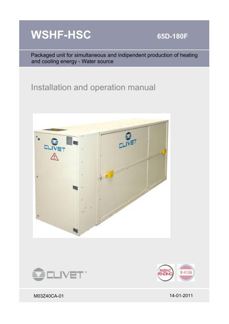
GENERAL 11.4 UNIT IDENTIFICATIONSerial number labelThe serial number label is positioned on the unit, generallynext to the electrical panel, and allows you to indentify all theunit features.The serial number label has not to be removed for any reason.It reports the regulations indications such as:Type of unitseries → WSHF- XSCsize → 65D, 180F eccserial number12 characters → Axxxxxxxxxxxyear of manufacturewiring diagram numberelectrical datamanufacturer logo and addressSerial numberIt identifies uniquely each unit.It identifies specific spare parts for the unit.Intervention requestsNote data from the serial number label and write them in thetable sideways, so you will find them easily when needed.In case of intervention you have to provide the data indicatedsideways.It meets the needs for heating and cooling in the building ofany proportionWhen the heating load and the cooling load are equivalent,the recovery is total, without the use of the water sourceWhen the heating load is in predominant, the energy excess isdischarged in the water sourceWhen the heating load is predominant, the necessary energyis taken from the water source (renewable source according toeuropean regulation RES).SerieSizeSerial numberYear of manufactureWiring diagram1.6 ACCESSORIESsteel mesh strainer to be mounted at the exchanger inlet.Should the filter not be installed in the water system, Clivetdeclines all responsibility and the warranty on the equipmentautomatically expires .compressor suction shut-off valvehigh and low pressure gaugesAnti-ice electric heaters utility side for hydronic group1.5 UNIT DESCRIPTIONSPINSAVER can generate hot water and chilled watersimultaneously, using the SPINCHILLER technologycombined with the total functional switching on the hydrauliccircuit. This is realized through reliable automatic switchingvalves, accurately following the building loads and allowingthe user to recover the highest amount of heating and coolingenergy.The refrigeration circuit, therefore, remains simple, withoutcycle inversion (therefore no pressure drops for the four-wayvalve) and with all the benefits of the SPINCHILLERproduction technology that represent the highest level offunctionality, both in terms of efficiency and reliability.phase monitorpower factor correction capacitors (cosfi > 0.9)Free contacts for compressor stateSoft startermicroprocessor remote control moduleCAN/LON WORKS serial converter kitCAN/MODBUS serial converter kitCAN/BACnet serial converter kitRubber antivibration mounts kitOutdoor installation (only for acustic configuration EN)5
2RECEPTION2.1 PRELIMINARY INFORMATIONStart hoisting the unit .Operate in compliance with safety regulations in force .For detailed information (dimensions, weight, technicalcharacteristics etc.) please refer to the TECHNICALINFORMATION section.Use single protection devices : gloves, glasses etcLifting beam with spacers2.2 DELIVERY CONTROLBefore accepting the delivery you have to check:that the unit hasn’t been damaged duringtransportthat the materials delivered correspond with thatindicated on the transport document comparing thedata with the identification label positioned on thepackaging.In case of damage or anomaly:write down on the transport document thedamage you found and quote this sentence:"Conditional acceptance — clear evidence ofdeficiencies/damages during transport".Contest by fax and registered mail with advice ofreceipt to supplier and the carrier.BAAny disputes must be made within the 8 days owing thedelivery. Complaints after this period are invalid.2.3 STORINGObserve external packaging instructions .2.4 HANDLINGVerify unit weight and handling equipment liftingcapacity .Identify critical points during handling (disconnected routes,flights, steps, doors).Check the position of the centre of gravity in the TECHNICALINFORMATIONS—DIMENSIONS section.ABefore starting the handling, make sure that the unit is stable.Use protections not to damage the unit.2.5 HOISTING using a CRANE or SIMILARSlide the provided lifting pipes into the holes in the base ofthe unit .BPosition the ends of the pipes that protrude from the unitso that you can insert the provided shear pins into theproper holes (standard).Fit the lifting belts over the pipes between the safety rodsand the base of the unit (see drawing).2.6 PACKAGING REMOVINGAGradually bring the lifting belts under tension, making surethey are positioned correctly. Make sure the unit is alwaysin steady equilibriumBe careful not to damage the unit.Recycling and disposing the packaging material inconformity with local regulations.6
POSITIONING 33.1 PRELIMINARY INFORMATION 3.4 FRESH AIR PROBEOperate in compliance with safety regulations in force.For detailed information (dimensions, weight, technicalcharacteristics etc.) please refer to the TECHNICALINFORMATION section.Use single protection devices : gloves, glasses etc.During positioning consider these elements :technical spaces requested by the unit and the systemchoice of the unit installation placeelectrical connectionswater connections3.2 FUNCTIONAL CLEARANCESThe external probe allows to automatically change the unit setpoint according to the external enthalpy (temperature +humidity).It is then possible to optimize the unit energy efficiency.POSITIONINGThe sensor should not be influenced by factors that candistort the reading (eg direct sunlight, air exhausted from thefan or other sources, contact with the unit structure or otherheat sources, accumulations of snow / ice).Examples to position the external probe :ABCroofunder a terraceif at free wall provide a small roofingThe functional clearances have to :guarantee the unit good operatingallow the maintenance operationssafeguard the authorized operators and the exposedpersonRespect the functional clearances indicated in theTECHNICAL INFORMATION - DIMENSIONS section.Double the functional clearances if more units are aligned.3.3 POSITIONING3.5 VIBRATION ISOLATORSWith a supported chassisThe unit has been designed to be installed :INDOOROUTDOOR (ONLY EN CONFIGURATION)in fixed positionin premises with Max ambient temperature= 40 °Cin premises with Max ambient RH = 50% at 40 °CLimit the vibration transmission:use vibration isolators on the unit support pointsinstall the flexible joints on the water connections.Installation criteria:safe accessible positionavoid flood-prone places;verify the unit weight and bearing point capacity;verify that all bearing points are aligned and levelledinstall the unit raised from the groundSAFETY VALVE GAS SIDEThe installer is responsible for evaluating the opportunity ofinstalling drain tubes, in conformity with the local regulations inforce ( EN 378 )1. Min recommended dimensions2. Cable brackets in the cement (not supplied)3. Cement base* height without chargeWith a jack for leveling the unit1. min recommended dimensions2. jack for leveling the unit3. plate4. cable brackets in the cement (not supplied)5. Cement base* height without charge7
4WATER CONNECTIONS4.1 PRELIMINARY INFORMATIONSelection and installation of system components must becarry out by installer.Following a series of instructions that must be integrated withwhat required by local regulations and by the code of practise.4.2 WATER FLOW-RATEThe project water-flow must be:inside the exchanger operating limits (see the pressuredrop curves in the TECHNICAL INFORMATION section)Guarantee, also with variable system conditions (forexample in systems where some circuits are bypassed inparticular situations)4.3 COMPONENTSINTERCEPTING VALVESInstalled on the input and output, they allow to carry out allthe maintenance operations and possible without emptyingthe installation.THERMOMETERS AND PRESSURE GAUGES:Installed on the input and output of the main parts facilitatethe controls and the maintenance.BLEED VALVES :Installed in all the highest points of the system, they allowthe venting from the circuit.BLEEDING COCKS :Installed at the lowest points of the circuit, so as to allowemptying .EXPANSION TANK :It allows the system correct pressure to be maintained atthe water temperature changing. It has to be sizedaccording to the system water content.WATER FILTER :If it is not built-in, it has to be immediately installed at theunit water inlet, in a position easily accessible for cleaning.Mesh dimension:1,6 mm 2The filter should never be removed, the operation will voidthe warranty.SUPPORTS :for the weight of the water piping that must not rest on theunit fittings.FLOW SWITCHas a component of the system must always be provided.EXCHANGER BYPASSto perform the chemical cleaning of the exchanger withoutdisconnecting the unit.4.4 CONNECTION SCHEMAA heat circuitB source circuitC cool circuitD supplying limit1 heating exchanger (condenser)2 cooling exchanger (evaporator)3 differential pressure switch4 vent5 circulating pumps6 charged installation pressure switch7 safety valve (6 Bar)8 discharge valve9 pressure gauge10 filter (it can be supplied separately)11 expansion tank12 inertial storage (discretionary)13 antivibration joints14 intermediate exchanger15 cocks8
WATER CONNECTIONS44.5 OPERATION SEQUENCEBefore connecting the unit, carefully wash the system by fillingit and emptying it several times with clean water.Ignoring this operation will lead to several filter cleaninginterventions and at worst cases can cause damages to theexchangers and the other parts.Execute leakage test before isolate the pipes.To avoid heat dispersions and formation of condensate isolateall the pipes.Leave various point of service free (wells, vent-holes etc )4.9 VICTAULIC CONNECTIONSTake away the supplied connection union by acting on theconnection joint Victaulic.Weld the union to the installation pipe.Perform the connection between the installation pipe andthe evaporator, using the joint.Do not weld the system pipe with the Victaulic connection jointattached.The rubber gasket might be irreparably damaged .4.6 WATER QUALITYThe water quality can be checked by qualified personnel.The factors to analyse are the following:Adopt measures to prevent the risk of freeze if the unit andthe relevant water connections are subject to temperaturesnear 0°C .For example:Inorganic saltspHBiological load (seaweeds etc)Suspended solidsDissolved oxygenWater with inadequate characteristics can cause:pressure drop increaseenergy efficiency decreasecorrosive symptom increase4.7 RISK OF FREEZEmix the water of the system with glycolprotect the tubes with heating cables under the tubesinsulationempty the system in the case of long stops and check that:no taps are closed so they can not trap the water,even after emptyingthere are no low points where the water can stagnateeven after emptying; blow if necessary4.10 INTERMEDIATE EXCHANGERSPINSAVER is designed to work with intermediate exchangeron the source side (to be handled by the Customer).This protects the machine exchangers from dirt, obtaining ahigher stability of performance over time.DIMENSIONINGSource side (well) :DT = weelT– groundwater return T → regulatory constraintQ = Pmax / (c p x DT) → pumping concessionsUnit side :summer eventwinter eventTDTQQ variable (hydropack)DT = 10 °C → Pt / (c p x Q)Q unit nominalDT = 5 °C → Pf / (c p x Q)temperaturetemperature differenceflowPmax max capacityPtPfc pheating capacitycooling capacityspecific heat at constant pressure and temperature4.8 ANTI-FREEZE SOLUTIONSConsider that the use of anti-freeze solution determines anincrease in a pressure drop.Make sure that the glycol type utilized is inhibited (notcorrosive) and compatible with the hydraulic circuitcomponents (pump etc).Do not use different glicol mixtures (ex. ethylene withpropylene)ABCA: inlet T B: return T C: well T9
4 WATER CONNECTIONSINTERMEDIATE EXCHANGER : ALTERNATIVE PLANTDEDICATED EXCHANGERcomplete independenceMaintenance without installationshutdownSINGLE EXCHANGERUnit autocontrolMaintenance with installation shutdownABOUNDING EXCHANGERSPossible solutionsUnit autocontrolMaintenance without installation4.11 GROUND WATERThe distance between feeding well and absorbent well must be at least of 15 m (impediment of the short-circuits). The availablevolumes and water quality must be cleared in advance with pumping tests.The groundwater must have chemical and physical characteristics that do not affect the integrity of the SPINsaver mechanical andhydraulic parts in order to be used as a source of thermal energy (see table). It is anyway possible to use groundwater with chemicaland physical characteristics not suitable as a heat source, by adding an external exchanger.Substance description Limit value Contraindications for exceeding the limit valuesHardness < 10°FpH value 7,5 - 9 Possible corrosion of stainless steel with percentages too highOxygenConductibility< 2 mg/l< 500 uS/cmIron < 2 mg/l With oxygen involves the infiltration of ocher in drainage wellManganese < 1 mg/l With oxygen involves the infiltration of ocher in drainage wellNitrate< 70 mg/lSulphate < 70 mg/l Possible corrosion of stainless steel with percentages too highChlorine compounds < 300 mg/l Possible corrosion of stainless steel with percentages too highCarbon dioxide free radicalAmmonium< 10 mg/l< 20 mg/l10
ELECTRICAL CONNECTIONS 55.1 PRELIMINARY INFORMATIONThe characteristics of the electrical lines must be determinedby specialized personnel able to design electrical installationsin conformity with regulations in force.The protection devices of the unit power line must be able tostop the presumed short circuit current, whose value must bedetermined in function of system features.The power cables and the protection cable section must bedefined in accordance with the characteristics of the adoptedprotections.All the electrical operations must be performed by qualifiedpersonnel as required by the regulations in force, educatedon the risks related to these operations.Operate as required by the safety regulations in force.5.2 ELECTRICAL DATAThe serial number label reports the unit specific electricaldata, included any electrical accessories.The electrical data indicated in the technical bulletin and in themanual refer to the standard unit, accessories excluded.Refer to the electrical data report on the serial number label.5.4 SIGNAL LINES/DATA-LAYDo not overpass the maximum power allowed, which varies,according to the type of signal.Lay the cables far from power cables or cables having adifferent voltage and that are able to emit electromagneticdisturbances.Do not lay the cable near devices which can generateelectromagnetic interferences.Do not lay the cables parallel to other cables; cable crossingsare possible, only if at 90°.Connect the screen to the ground, only in case of nodisturbances .Guarantee the continuity of the screen for the entire extensionof the cable.Respect impendency, capacity and attenuation indications.5.5 ELECTRIC LINE INPUTserial numberlabelVOLTAGEFLA (A)FLI (kW)Fix the cables : if vacated they may be subject to tearing.F.L.A. full load ampereFull load current at max admissible conditionsF.L.I.Full load inputFull load power input( at max. admissible condition )The cables must not touch the compressors and therefrigerant piping (they reach high temperatures)5.3 CONNECTIONS1. Refer to the unit electrical diagram (the number of thediagram is shown on the serial number label)2. Verify that the network has characteristics conforming tothe data shown on the serial number label3. Before starting work, verify that the sectioning device atthe start of the unit power line is open, blocked andequipped with sign warning4. First create the earthing connection5. Shelter the cables using adequate measure fairleads6. Before powering the unit ensure that all the protectionsthat were removed during the electrical connection, havebeen restored.11
5ELECTRICAL CONNECTIONS5.6 ELECTRICAL PANELXCTerminal block of the CustomerconnectionsAP7Main control moduleAP8Compressors 1-2-3 control moduleAP9Compressors 4-5-6 control moduleAP12T connector moduleAP14Phase monitor moduleAP15Master control moduleAP17Local terminal of the user interfaceAP35CAN TO MODBUS converter moduleAP50Buffer batteryAP51-52Management card of the electronicthermostaticsAP206QS1Pump voltage controllerMain isolator switchXCQM1..6Compressor magnetothermic switchesKM1..6Compressor contactorsL1-L2-L35.7 CONNOCTIONS PERFORMED BY THE CUSTOMERSA1remote on-offKMSsource pump controlBT7external temperature probeALMcumulative lock signallingHL1...6compressors status signalling12
ELECTRICAL CONNECTIONS 55.8 REMOTE TERMINAL - OPTIONAWG 20/22 - MAX 200 mt4 3 2 14 3 2 16 5 4 3 2 1 06 5 4 3 2 1 0REMOTE CONTROL ADDRESSINGOperations to be performed to the remote control :1. simultaneously press keys ↑↓←ATerminal Adr 312. A appearsI/O Board 13. setting address keyboard = 314. setting address IOBOARD = 15. press ← B appears6. press ← C appears7. setting TERM 1 = 32 PRBTerminal Configpress ENTERto continue8. setting TERM 2 = 31 SH9. confirm10. simultaneously press keys ↑↓←11. select TAST 31, setting IOBOARD = 2CP 01 Adr Priv / SharedTrm1 32 PR12. D appearsTrm231 SH13. press twice key ←14. E appearsTrm3NoneOK ? S15. check TERM 1 = NONE and TERM 2 = NONEDTerminal Adr 31I/O Board 2EP 02 Adr Priv / SharedTrm1Trm2NONENONETrm3 NONE OK ? S13
++5ELECTRICAL CONNECTIONS5.9 SERIAL COMMUNICATION MODULERS 485 SERIAL PORTWith MODBUS protocolSERIAL COMMUNICATION MODULEwith LONWORKS protocolUNIT 2- + GNDXCUNIT 1-GNDUNIT 3-GNDBACNET SERIAL COMMUNICATIONMODULEETHERNET SERIAL COMMUNICATIONMODULECABLE REQUIREMENTCouple of conductors twisted and shieldedSection of conductor 0.22mm2…0,35mm2Nominal capacity between conductors < 50 pF/mNominal impedance 120 ΩRecommended cable BELDEN 3105 A14
ELECTRICAL CONNECTIONS 5Master slave connection(max 10 unit)Supervision15
6START-UPPRELIMINARY CHECKSSynthetic reminder of the points to check and of the operations to perform for the unit start-up.For details on the points mentioned in the check list refer to various chapters of the manual.√Preliminary checks - unit power supply OFF1 access in safety2 functional clearances3 structure integrity4 unit on vibration isolators5 unit input water filter + shutt-off valve for cleaning6 antivibration isolators on the water connections7 expansion tank (volume > 5% installation content)8 installation cleaning9 Installation charge + possible glicol solution + corrosion inhibitor10 installation in pressure11 installation vent12 outdoor air probe position13 visual check of the refrigerant circuit14 earthing connection15 power supply features16 electrical connections provided by the customer16
START-UP 6START-UP SEQUENCE√Start-up sequence—unit power supply ON1 compressor crankcase resistances in operation from at least 8 hours2 no-load voltage measure3 phase sequence check4 pump manual start-up and flow check5 ON unit6 load voltage measure and absorptions7 check of the liquid light (no bouble)8 measure of the supply and return water temperature9 measure of the super-heating and sub-cooling10 check that no anomalous vibrations are present11 set-point personalization12 unit documentation available17
6START-UP6.1 PRELIMINARY INFORMATION6.5 ELECTRICAL CIRCUITThe indicated operations should be done by qualifiedtechnician with specific training on the product.The service centres shall perform by request the start-up; theelectrical, hydraulic connections and the remaining work on thesystem are provided by the installer.Agree upon the start-up date with the service centre sufficientlyin advance6.2 PRELIMINARY CHECKSBefore checking, please verify that :1. the unit should be installed properly and in conformitywith this manual.2. the electrical power supply line should be sectioned atthe beginning.3. the line sectioning device is open, locked andequipped with the suitable warning signs.4. ensure no voltage is present6.3 REFRIGERANT CIRCUITVerify that the unit is connected to the ground plant .Check tightening of the conductors: the vibrations caused byhandling and transport might cause loosing .Feed the unit by closing the sectioning device, but leave it onOFFCheck the voltage and frequency net values which must bewithin the limits:400/3/50 +/- 6%Control the unbalancing of the phases:Example :it must be lower than 2% .L1 L2 L3388V377V379V1. Visually check the refrigerating circuit: the presence of oilstains can mean leakage (caused, for example, bytransport, handling or other).2. Open the cocks of the refrigerator circuit3. Check that the refrigerant circuit is in pressure: use the unitpressure gauges, if present, or some service pressuregauges.4. Check that all the service outlets are closed with propercaps; if caps are not present a leak of refrigerant can bepossible1)2)3)388 + 379 + 377= 381 (A)3MAX - A = 388 – 381 = 77S =Ax 100 = 1,83 OK6.4 HYDRAULIC CIRCUIT1. Before realizing the unit connection make sure that thehydraulic system has been cleaned up and the clearingwater has been drained .2. Check that the water circuit has been charged andpressurised .3. Check that the cut-off valves on the circuit are in the"OPEN" position.4. Check that no air is present in the circuit, if required,evacuate using the air bleeding valve placed at thesystem's high points.5. When using antifreeze solutions, make sure the glycolpercentage is suitable for the type of use envisaged.The operating out of the limits can cause irreversible damagesand makes decay the warrantyTo make sure that the resistances are working, check thepower input .Connect the oil resistances on the compressor crankcase atleast 8 hours before the compressor is to be start% weight of ethylene glycol 10 20 30 40Freezing point (°C) -3.9 -8.9 -15.6 -23.4Safety temperature (°C) -1 -4 -10 -1918
START-UP 66.6 REMOTE CONTROLSCheck that the remote controls (ON-OFF etc) areconnected and, if necessary, enabled with the respectiveparameters as indicated in the ELECTRICALCONNECTIONS section.Check that probes and optional components areconnected and enabled with the respective parameters(ELECTRICAL CONNECTIONS section and followingpages)6.7 EVAPORATOR WATER FLOW-RATECheck that the difference between the temperature ofexchanger return and supply water corresponds to poweraccording to this formula:unit cooling power (kW) x 860 = Dt (°C) x flow rate (L/h).The cooling power is shown in the table of the GENERALTECHNICAL DATA included in this manual, referred tospecific conditions, or in the tables on COOLINGPERFORMANCE in the TECHNICAL BULLETIN referred tovarious conditions of use.Check for water side exchanger pressure drops:Determine the water flow rate.Measure the difference in pressure between exchangerinput and output and compare it with the graph on WATERSIDE EXCHANGER PRESSURE DROPSThe measurement of pressure will be easier if pressuregauges are installed as indicated in the DIAGRAM OFSUGGESTED WATER CONNECTIONS .Absorptions of the different electric loads (compressors,fans, pumps etc)<strong>Temp</strong>eratures and flows of the different fluids (water, air)both in input and in output from the unit<strong>Temp</strong>erature and pressures on the characteristic points ofthe refrigerating circuit (compressor discharge, liquid,intake)The measurements must be kept and made available duringmaintenance interventions.6.10 CE 97/23 PED DIRECTIVE97/23 CE PED DIRECTIVE gives instructions for installers,users and maintenance technicians as well. Refer to localactuation norms :Briefly and as an example, see the following :COMPULSORY VERIFICATION OF THE FIRSTINSTALLATION:only for units assembled on the installer’sbuilding site (for ex. Condensing circuit + directexpansion unit)CERTIFICATION OF SETTING IN SERVICE:for all the unitsPERIODICAL VERIFICATIONS:to be executed with the frequency indicated bythe Manufacturer (see the MAINTENANCEINSPECTIONS paragraph6.11 OPERATING AT REDUCED LOAD6.8 CONDENSER WATER FLOW-RATECheck that the difference between the temperature ofexchanger return and supply water corresponds to poweraccording to this formula:unit cooling power + power absorbed by compressors (kW)x 860 = Dt (°C) x flow rate (L/h).The data is shown in the table of the GENERAL TECHNICALDATA included in this manual, referred to specific conditions,or in the tables on HEATING PERFORMANCE in theTECHNICAL BULLETIN referred to various conditions of use.Check for water side exchanger pressure drops:Determine the water flow rate.Measure the difference in pressure between exchangerinput and output and compare it with the graph onWATER SIDE EXCHANGER PRESSURE DROPS.The measurement of pressure will be easier if pressuregauges are installed as indicated in the DIAGRAM OFSUGGESTED WATER CONNECTIONS .The units are equipped with partialization steps and they can,therefore, operate with reduced loads.However a constant and long operation with reducedload with frequent stop and start-up of the compressor/s cancause serious damages for the lack of oil return.The above-described operating conditions must beconsidered OUT of standards.In the event of compressor break, due to the operating in theabove-mentioned conditions, the guarantee WILL NOT BEVALID and Clivet spa declines any responsibility.Check periodically the average operating times and thefrequency of the compressors starts: approximately theminimum thermal load should be such as to need theoperating of a compressor for at least ten minutes.If the average times are close to this limit, take the propercorrective actions.6.9 START-UP REPORTIdentifying the operating objective conditions is useful tocontrol the unit over time.With unit at steady state, i.e. in stable and close-to-workconditions, identify the following data :Total voltages and absorptions with unit at full load19
7CONTROL7.1 SYSTEM STRUCTURE12 3 4 5 61 pGD unit interface2 supervisor module(management of the water part, valves, pumps)3 MODULAR interfaceaccess to the manufacturer parameters(only authorized assistance centres)4 central module(management of the refrigerant part)5 compressors 1 2 3 moduleand electronic thermostatic valve6 compressors 4 5 6 moduleand electronic thermostatic valve7.2 KEY FUNCTIONSALARMSAccess to the alarm menuIt flashes with active alarmsPrgPROGRAMMINGAccess to the stata and parameter menuIt flashes with unit off by supervisor or digital inputEscOUTPUTBack to the previous menu.UPChange of the display windowIncreasing of the selected variableENTERAccess to the sub menu and to the settableparameters.Access to the system sub menu.DOWNChange of the display windowDecreasing of the selected variable20
CONTROL 77.3 MENU STRUCTUREALARMSHOMEPAGEON OFFACTIV ALARMSMODEALARM HISTORICALLOGALARM RESETHISTORICAL RESETSETPOINTCLOCKCOOL / HEATINPUTS OUTPUTSDIGITAL OUTPUTSDIGITAL INPUTSANALOGICAL OUTPUTSANALOGICAL INPUTSVARIOUSGENERALRECOVERY TESTRECOVERY INPUTRECOVERY MANAG.AUTOMATIC MODECARD CHANGEASSISTANCELANGUAGE CHANGEINFORMATIONHOURS WORKEDBMS CONFIG.ASSISTANCE PAR.MANUAL MANAG.MANUFACTURERINITIALIZATIONSOURCE VALVESTALKCANOPEN MAPCENTRALUNIT1 COMPR. 1UNIT1 COMPR2VARIOUS21
7CONTROL7.4 SWITCHING ON AND OFFpressSelect ON or OFFconfirmPress twice to return to the main mask7.5 THERMOREGULATIONThe thermoregulator is set on the use return temperature.The insertion and removing of the ccompressors is controlled by the supply temperature.22
CONTROL 77.6 INPUTS - OUTPUTSGr Id FunctionJ1 G-G0 24 Vdc or 24 Vacpower supply (0 on G0) .J2J3J4J5J6J7B1B2B3B4B5Y1Y2Y3Y4ID1ID2ID3ID4ID5ID6ID7ID8B6B7B8ID9ID10ID11ID12BT300 source temperature probeBT110 input temperature probe of the condenserBT107 input temperature probe heat utilisationBT108 output temperature probe heat utilisationYv102 modulating valve control output (3-way condenser)Yv202 modulating valve control output (3-way evaporator)206 bypass pump control output evaporator sideYv105 modulating valve control output (bypass onthe condenser)106 pump thermal (bypass heat utilisation) (opened=> alarm)FreeFreeFreeYv103 valve stop (source valve condenser side)(closed => valve off)Yv203 valve stop (source valve condenser side)(closed => valve off)Yv104 valve stop (source valve evaporator side)(closed => valve off)Yv204 valve stop (source valve evaporator side)(closed => valve off)FreeFreeFree101a pump thermal (condenser) (opened => alarmpump)201a pump thermal (evaporator) (opened => alarmpump)101b pump thermal (condenser) (opened => alarmpump)201b pump thermal (evaporator) (opened => alarmpump)J8ID13ID14206 bypass pump thermal of the evaporator (opened=> alarm pump) (delay sw 3 sec)Flx300 flow switch input (closed present flow)J9 - Telephonic connectorJ10 - Telephonic connector for unit terminal connectionJ11 - Connectors for the unit PLan net connectionJ12J13NO1NO2NO3NO4NO5NO6Control for the source activation request (closedactive request)Presence of unit cumulative alarm (closed presentalarms)FreeJ14 NO7 Free201b pump control (evaporator)106 pump control (bypass heat utilisation)Remote On/Off control Talk electronicsJ15 NO8 201a pump control (evaporator)J16NO9NO10NO11Control of the simultaneous Yv103, Yv104 valveopening source condenser sideControl of the simultaneous Yv103, Yv104 valveclosing source condenser sideFreeJ17 NO12 101b pump control (condenser)J18 NO13 206 pump control (bypass cool utilisation)J19J20J21J22ID15ID16Y5Y6B9B10ID17ID18NO14NO15NO16NO17NO18FreeFreeFreeFreeBT207 input temperature probe cool utilisationBT208 output temperature probe cool utilisationFreeFree101a pump control (condenser)FreeControl of the simultaneous Yv203, Yv204 valveopening source evaporator sideControl of the simultaneous Yv203, Yv204 valveclosing source evaporator sideFree23
7CONTROL7.7 ALARMSALARMSHOMEPAGEACTIV ALARMSALARM HISTORICALLOGALARM RESETHISTORICAL RESETBefore resetting an alarm, identify and remove the cause thatgenerated it.Repeated reset may cause irreversible damages asmalfunction of the system itself.In case of doubt please contact a Service Centre.IN CASE OF ALARMbuzzer lightingRed LED lighting of the ALARM buttonPress the ALARM buttonThe buzzer is switched offThe display visualizes the alarm mask.With more active alarms, the mask of the first alarm isdisplayed ; with the arrow buttons it is possible to display theothers.ALARM RESETTo reset the alarms and delete the messages :position on the alarm maskspress the Alarm buttonif the causes of the are disappearedthe masks disappearthe red led goes outNO ACTIVE ALARM will appearIf the cause of one or more alarms is still active, justdisappear the disabled alarms ; the others aredisplayed and the buzzer and the red led arebrightened again .24
CONTROL 7ALARMS LISTE500 time board fault - not connectedE501 Extended memory faultE001 H2O IN temp. probe faultE002 H2O OUT temp. probe faultE003 Outside air temp. probe faultE004 Water Reset input faultE005 Outside RH% probe faultE006 Thermal cut-out alarm pump 1E007 Thermal cut-out alarm pump 2E008 Flow switch alarmE009 System pressure alarmE010 Phase monitor alarmE011 Antifreeze alarmE012 Antifreeze pre-alarmE013 Change CENTRAL pumpE014 Unit configuration alarmE015 Demand Limit input faultE016 Can net disconnectedness on control moduleE017 Inhibits control in heatingE018 Incongruent deltaT alarmE019 Ext low temperature alarmUnit 1 - Compressor 1 E101 Cond./ Evap. temp. probe faultUnit 1 - Compressor 1 E102 Condensing pressure probe faultUnit 1 - Compressor 1 E103 Evaporation pressure probe faultUnit 1 - Compressor 1 E104 Recovery temp. probe faultUnit 1 - Compressor 1 E105 High pressure alarmUnit 1 - Compressor 1 E106 Low pressure alarmUnit 1 - Compressor 1 E107 Fan/Pump thermal cut-out alarmUnit 1 - Compressor 1 E111 Cond. / Evap. H2O flow alarmUnit 1 - Compressor 1 E112 High pressure pre-alarm 1Unit 1 - Compressor 1 E113 High pressure pre-alarm 2Unit 1 - Compressor 1 E114 Low pressure pre-alarmUnit 1 - Compressor 1 E115 Force defrost alarmUnit 1 - Compressor 1 E116 Max Press. diff. alarmUnit 1 - Compressor 1 E117 Recovery H2O flow alarmUnit 1 - Compressor 1 E118 Heat recovery HP pre-alarmUnit 1 - Compressor 1 E123 TA TEE alarmUnit 1 - Compressor 1 E124 TS TEE alarmUnit 1 - Compressor 1 E125 max TS TEE prealarmUnit 1 - Compressor 1 E126 SPI faulty AlarmUnit 1 - Compressor 1 E127 motor TEE power fail alarmUnit 1 - Compressor 1 E128 stepper motor error alarmUnit 1 - Compressor 1 E108 Compressor 1 thermal cut-out alarmUnit 1 - Compressor 1 E119 Oil differential pressure alarmUnit 1 - Compressor 1 E122 Min Press. diff. alarmUnit 1 - Compressor 1 E121 BP2 prealarmUnit 1 - Compressor 1 E120 Condenser frost alarmUnit 1 - Compressor 1 E109 Compressor 2 thermal cut-out alarmUnit 1 - Compressor 1 E110 Compressor 3 thermal cut-out alarmUnit 1 - Compressor 2 E101 Cond./ Evap. temp. probe faultUnit 1 - Compressor 2 E102 Condensing pressure probe faultUnit 1 - Compressor 2 E103 Evaporation pressure probe faultUnit 1 - Compressor 2 E104 Recovery temp. probe faultUnit 1 - Compressor 2 E105 High pressure alarmUnit 1 - Compressor 2 E106 Low pressure alarmUnit 1 - Compressor 2 E107 Fan/Pump thermal cut-out alarmUnit 1 - Compressor 2 E111 Cond. / Evap. H2O flow alarmUnit 1 - Compressor 2 E112 High pressure pre-alarm 1Unit 1 - Compressor 2 E113 High pressure pre-alarm 2Unit 1 - Compressor 2 E114 Low pressure pre-alarmUnit 1 - Compressor 2 E115 Force defrost alarmUnit 1 - Compressor 2 E116 Max Press. diff. alarmUnit 1 - Compressor 2 E117 Recovery H2O flow alarmUnit 1 - Compressor 2 E118 Heat recovery HP pre-alarmUnit 1 - Compressor 2 E123 TA TEE alarmUnit 1 - Compressor 2 E124 TS TEE alarmUnit 1 - Compressor 2 E125 max TS TEE prealarmUnit 1 - Compressor 2 E126 SPI faulty AlarmUnit 1 - Compressor 2 E127 motor TEE power fail alarmUnit 1 - Compressor 2 E128 stepper motor error alarmUnit 1 - Compressor 2 E108 Compressor 1 thermal cut-out alarmUnit 1 - Compressor 2 E119 Oil differential pressure alarmUnit 1 - Compressor 2 E122 Min Press. diff. alarmUnit 1 - Compressor 2 E121 BP2 prealarmUnit 1 - Compressor 2 E120 Condenser frost alarmUnit 1 - Compressor 2 E109 Compressor 2 thermal cut-out alarmUnit 1 - Compressor 2 E110 Compressor 3 thermal cut-out alarmE502 pump protection 101aE503 pump protection 101bE504 pump protection 201aE505 pump protection 201bE506 pump protection 106E507 pump protection 206E510 Closing Yv103 valve alarmE511 Opening Yv103 valve alarmE512 Closing Yv104 valve alarmE513 Opening Yv104 valve alarmE514 Closing Yv203 valve alarmE515 Opening Yv203 valve alarmE516 Closing Yv204 valve alarmE517 Opening Yv204 valve alarmE530 Talk board not connectedE531 BT107 inlet heat water loop probe alarmE532 BT108 outlet heat water loop probe alarmE533 BT207 inlet cool water loop probe alarmE534 BT108 outlet cool water loop probe alarmE535 BT300 source probe alarmE536 BT110 condenser inlet probe alarmE540 Source flow alarm25
7CONTROL7.8 MASTER - SLAVEMax. 10 unitsAll the units must have the parameter P502EnMasterSlave = 1Setting procedure.select ASSISTANCE PARAMETERSconfirmenter the assistance passwordAccess to ASSISTANCE PARAMETERSSelect CONTROLconfirmselect par 502set = 1press 4 times26
CONTROL 7MASTER SLAVE ADDRESSINGThe units must be addressed as indicated in the tablesideways .Addressing procedure:1. set pGD keypad = 02. set the base card as indicated in the table3. set pGD keypad as indicated in the table4. proceed with the other unitsUnit PCO3 base card pGD keypadUnit 1 1 15Unit 2 2 16Unit 3 3 17Unit 4 4 18Unit 5 5 19Unit 6 6 20Unit 7 7 21Unit 8 8 22Unit 9 9 23Unit 10 10 241 set the pGD keypad = 0Press for 5 secondsdisplay address setting......32set = 0display address changed2 set the base card as indicated in the tablePress at the same timeselftest please waitKeep pressed for 10 sec pLan address = 0set as indicated in the tableconfirm3 set the pGD keypad as indicated in the tableRepeat the procedure as at point 127
7CONTROLMASTER SLAVE SWITCHING ON AND OFFselect ON or OFFPress twice28
IIIIII? ESC? ESC? ESC? ESC? ESC? ESCHOMEHOMEHOMEHOMEHOMEHOMECONTROL 77.9 MODULAR INTERFACEUnit ON / OFFF1 = not used (HEAT / COOL change)F2 = ALARM menu accessF3 = SET POINT, TIME BANDS, CLOCK accessF4 = STATA menu accessHELP parameter descriptionsBack to the previous screenBack to the main menuONLed = on for unit in ONLed = off for unit in OFFUnit statusON – ECO – OFFEnabled time bandsAlarm signalling in progressNo alarm in progressCOOL coolingHEAT Not used (heating)12.2 INLET temperature9.3 OUTLET temperature7.0 Current set point7.10 SETUP MENUSET UP menu :To enter in the SETUP menubutton F3 SETUPPARAMETERSmodifies set pointNOT FOR USESCHEDULINGenables/dis. time periodsTo select the submenubuttons ▲▼ F2 – F3*CLOCK SETUPset the clockTo accessbutton F1 ENTERID Tast-Cen( ONLY ATC )To scrolling voicesbuttons ▲▼ F2 - F3PASSWORD( ONLY ATC )To go back a level of the menubutton ESC* set same time MASTER keyboardTo go back to the main menubutton HOME29
IIIIIII? ESC? ESC? ESC? ESC? ESC? ESC? ESCHOMEHOMEHOMEHOMEHOMEHOMEHOME7CONTROL7.11 ALARMSAlarms are replicated on PGD keyboardALARM menu :To enter in the ALARM menubutton F2 ALARMVIEW ALARMTo visualize the alarm in progressSTORE ALARMTo visualize the historical alarmTo select VIEW ALARMbuttons ▲▼ F2 – F3DEL STORETo delete the historical alarmTo accessbutton F1 ENTERTo scroll the active alarmsbuttons ▲▼ F2 - F3To reset the alarm in progressbutton F1 ENTERTo go back a level of the menubutton ESCTo go back to the main menubutton HOMEAn alarm list is associated with the inputs of each electronic module of the unit.On the display appears a code that identifies the electronic module and the alarm code.Example :U_1 CMP_1 E105U_1 CMP_1 = compressor 1 moduleE105 = high pressure alarmALARM STRUCTURECENTRAL (CEN)list of alarmsUnit_1 (U_1)Mod_comp1 (CMP1_1)list of alarmsMod_comp2 (CMP_2)list of alarms30
CONTROL 7CENTRAL MODULEE001 H2O IN temp. probe fault on control moduleE002 H2O OUT temp. probe fault on control moduleE003 Outside air temp. probe faultE004 Water Reset input faultE005 Outside RH% probe faultE006 Thermal cut-out alarm pump 1 on control moduleE007 Thermal cut-out alarm pump 2 on control moduleE008 Flow switch alarm on control moduleE009 System pressure alarmE010 Phase monitor alarmE011 Antifreeze alarm on control moduleE012 Antifreeze pre-alarm on control moduleE013 Change CENTRAL pumpE014 Unit configuration alarmE015 Demand Limit input faultE016 Can net disconnectedness on control moduleE017 Inhibits control in heatingE018 Incongruent deltaT alarmE019 Ext low temperature alarmCOMPRESSOR MODULEE101 Cond./ Evap. temp. probe faultE102 Condensing pressure probe faultE103 Evaporation pressure probe faultE104 Recovery temp. probe faultE105 High pressure alarmE106 Low pressure alarmE107 Fan/Pump thermal cut-out alarmE111 Cond. / Evap. H2O flow alarmE112 High pressure pre-alarm 1E113 High pressure pre-alarm 2E114 Low pressure pre-alarmE115 Force defrost alarmE116 Max Press. diff. alarmE117 Recovery H2O flow alarmE118 Heat recovery HP pre-alarmE108 Compressor 1 thermal cut-out alarmE109 Compressor 2 thermal cut-out alarmE110 Compressor 3 thermal cut-out alarmE213 Module not connectedE119 Oil differential pressure alarmE120 Condenser frost alarmE121 BP2 prealarmE123 TA TEE alarmE124 TS TEE alarmE125 max TS TEE prealarmE126 max TS TEE prealarmE127 power fail alarmE128 stepper motor error alarm31
IIIIII? ESC? ESC? ESC? ESC? ESC? ESCHOMEHOMEHOMEHOMEHOMEHOME7CONTROL7.12 STATAsubmenu:GENERALSUNIT 1To enter in the STATA menubutton F4 STATEmod_comp1mod_comp2To select the modulebuttons ▲▼ F2 – F3mod_comp3UNIT 2mod_evapTo accessbutton F1 ENTERmod_comp1mod_comp2mod_comp3To scroll the statabuttons ▲▼ F2 - F3mod_evapTo go back a level of the menubutton ESCTo go back to the main menubutton HOMETo each unit electronic module is associated a sub menu that allows the system stata to be visualized.STATA STRUCTUREGENERALSlist of alarmsUnit_1 (U_1)Mod_comp1 (CMP1_1)list of alarmsMod_comp2 (CMP_2)list of alarms32
CONTROL 7Index GENERAL stata UM0 Unit status1 Unit mode1=ON /0=OFF0=Cool, 1=Heat2 Actual set point °C (tenths)3 Inlet temperature °C (tenths)4 Outlet temperature °C (tenths)5 Number of steps activated6 Current step value (compensations) °C (tenths)7 Step activation timer sec8 Step activation dynamic TimeScan sec9 CompExt °C (tenths)10 CompWR °C (tenths)11 CompCar °C (tenths)12 CompSpunti °C (tenths)13 CompDuty °C (tenths)14 Outside temperature °C (tenths)15 Outside humidity %16 Free Cooling valve percentage %17 Free Cooling flow percentage %18 Free Cooling valve control19 Pump 1 status20 Pump 2 status1=ON /0=OFF1=ON /0=OFF1=ON /0=OFF21 Water Reset %22 Demand Limit %60 Digital input68 Water flow analogic out69 Pump module digital out71 BitMap connected nodes MS72 Hours pump 1 PMP73 Hours pump 2 PMP74 Hours pump 3 PMPbit map of abytebit map of abytebit map of abyteIndex UNIT_1 – MOD COMP_1 stata unità di misura29 Compressor 1 1=ON / 0=OFF30 Compressor 2 1=ON / 0=OFF31 Compressor 3 1=ON / 0=OFF32 Cp 1 timer status 1=ON / 0=OFF33 Cp 2 timer status 1=ON / 0=OFF34 Cp 3 timer status 1=ON / 0=OFF35 Valve 1 c1 status 1=ON / 0=OFF36 Valve 2 c1 status 1=ON / 0=OFF37 Valve 3 c1 status 1=ON / 0=OFF38 Valve 1 c2 status 1=ON / 0=OFF39 Valve 2 c2 status 1=ON / 0=OFF40 Valve 3 c2 status 1=ON / 0=OFF41 Valve 1 c3 status 1=ON / 0=OFF42 Valve 2 c3 status 1=ON / 0=OFF43 Valve 3 c3 status 1=ON / 0=OFF44 Liquid solenoid 1=ON / 0=OFF45 Coil temperature °C ( tenths)46 Recovery temperature °C ( tenths)47 Condensation pressure bar48 Evaporation pressure bar49 Fan Status bar50 Defrost Status 1=ON / 0=OFF51 Defrost count time sec52 Compressor 1 operating time53 Comp. 1 starts54 Compressor 2 operating time55 Comp. 2 starts56 Compressor 3 operating time57 Comp. 3 starts58 Recovery valve 1=ON / 0=OFF59 Recovery PREHP delay sec61 Digital input bit map of a byte75 Daikin calculated power %76 PEvapOp bar77 Taspirazione °C(tenths)78 Tscarico °C(tenths)79 Valve opening %80 SuperHeat °C(tenths)81 SuperHeatSPOperativo °C(tenths)82 <strong>Temp</strong>SaturaCondensazione °C(tenths)33
8MAINTENANCE8.1 GENERAL8.6 WATER EXCHANGERMaintenance must be done by authorized centres or byqualified personnelThe maintenance allows to:maintain the unit efficiencyreduce the deterioration speed to whom every equipmentis subject over timeassemble information and data to understand the state ofthe unit efficiency and avoid possible damages8.2 INSPECTIONS FREQUENCYThe inspections should be carried out at least every six monthsThe frequency, however, depends on the use.In the event of frequent use it is recommended to planinspections at close intervals:frequent use (continuous or very intermittent use, nearthe operating limits, etc)critical use (service necessary).8.3 UNIT BOOKLETIt’s advisable to create a unit booklet to take notes of the unitinterventions.In this way it will be easier to adequately note the variousinterventions and aid any troubleshooting.Report on the booklet:datatype of intervention effectedintervention descriptioncarried out measures etc.It is very important for the exchanger to be able to provide themaximum thermal exchange. Therefore, it is essential for theinner surfaces to be clean of dirt and incrustations.Periodically check the difference between the temperature ofthe supply water and the condensation temperature. If thedifference is greater than 8°C–10°C it is advisable to clean theexchanger .The cleaning must be effected :with circulation in the opposite direction respect the normalonewith speed at least 1,5 times higher than the nominal onewith a suitable product moderately acid (95% water +5% phosphoric acid)after washing, rinse with water to inhibit the residues ofdetergent8.7 CIRCULATING PUMPSCheck :no leaksbearing status (anomalies are marked by abnormal noisesand vibrations)The closing of the terminal cover blocks and the correctcable gland positioning8.4 PUT AT RESTIf a long period of inactivity is foreseen:Turn off the power in order to avoid electrical risks ordamages by lightning strikesavoid the risk of frost (empty or add glycol to the parts ofthe system exposed to temperatures below zero, maintainpowered any anti-freeze resistances )It’s recommended that the starting-up after the stoppingperiod is performed by a qualified technician, especially afterseasonal stops or seasonal switch.When restarting, refer to what is indicated in the START-UPsection.Schedule technical assistance in advance to avoid hitchesand to guarantee that the system can be used when required.8.5 WATER FILTERCheck that no impurities prevent the correct passage of water.34
MAINTENANCE 88.8 CONTROL SHEETControls effected on ……………………..By……………………………...………………….of the Company ……………………………………………….STRUCTURE1. Presence of corrosionsHYDRAULIC CIRCUIT1. Water filter cleaning2. Check the exchanger efficiency3. Circulating pumpsELECTRICAL CIRCUIT1. Fixing control and cable insulation2. Electrical panel cleaning3. Capacity contactor status, terminal closing, cable insulation integrity4. Power-supply voltage and phase unbalancing (no load and on-load)5. Absorptions of the single electrical loads6. Test of the compressor crankcase resistancesREFRIGERANT CIRCUIT1. Leak check2. Operating parameters of the refrigerant circuitCONTROL AND CHECK1. Protective device test : safety valves, pressure switches, thermostats, flow switches etc2. Control system test: setpoint, climatic compensations, capacity stepping, air flow variations etc3. Control device test : alarm signalling, thermometers, probes, pressure gauges, etcNotes / interventions recommended to the owner*European regulation 303/2008:Refer to the local actuation regulations; in short and as an indication only the regulation prescribes that which follows.Companies and technicians that carry out installation, maintenance/repairs, leak control and recovery interventions must be CERTIFIED as prescribed bythe local regulations.The leak control must be carried out annually.35
9DECOMMISSIONING9.1 DISCONNECTIONOnly authorised personnel must disconnect the unit.Avoid leak or spills into the served area.Before disconnecting the unit, the following must berecovered, if present:- refrigerant gas- Anti-freeze solutions in the hydraulic circuitsWhen awaiting dismantling and disposal, the unit canalso be stored outdoors, as bad weather and rapidchanges in temperature will not cause damage to theenvironment, if the unit's electric, cooling and hydrauliccircuits are integral and closed.9.2 DISMANTLING AND DISPOSALTHE UNIT MUST ALWAYS BE SENT TO AUTHORISEDCENTRES FOR DISMANTLING AND DISPOSAL.When dismantling the unit, the fan, the motor and the coil, ifoperating, may be recovered by the specialist centres forreuse.All the materials must be recovered or disposed of incompliance with the corresponding national standards inforce.For further information on the decommissioning of the unit,contact the manufacturer .9.3 CE WEEE DIRECTIVEThe units covered by the legislation in question are markedwith the symbol on the side.With the aim of protecting the environment, all of our unitsare produced in compliance with CE Directive on wasteelectrical and electronic equipment (WEEE).The potential effects on the environment and on humanhealth due to the presence of hazardous substances areshown in the use and maintenance manual in the sectionon residual risks.Information in addition to that indicated below, if required,can be obtained from the manufacturer/distributor/importer,who are responsible for the collection/handling of wasteoriginating from equipment covered by CE-WEEE. Thisinformation is also available from the retailer who sold thisappliance or from the local authorities who handle waste.CE-WEEE directive requires disposal and recycling ofelectrical and electronic equipment as described therein tobe handled through appropriate collection, in suitablecentres, separate from collection for the disposal of mixedurban waste.The user must not dispose of the unit at the end of its lifecycle as urban waste. It must instead be handed over toappropriate collection centres as set forth by currentstandards or as instructed by the distributor.36
TECHNICAL INFORMATION 10Acoustic configuration: Standard (ST)/Extremely low noise(EN)GENERAL TECHNICAL SPECIFICATIONSSize 65D 70D 75D 80D 85D 90D 100D 110D 115D 120D 135E 150F 165F 180FCOOLING 100% - HEATING 100%Cooling capacity 1 kW 173 182 199 208 224 254 276 297 314 330 360 391 444 500Heat output 1 kW 224 237 257 269 289 327 356 383 407 428 466 506 574 646Compressor power input kW 51 55 58 61 65 73 80 86 93 98 106 115 130 147Total power input kW 51 55 58 62 65 73 80 87 93 98 107 116 130 148Global efficiency 7.73 7.59 7.80 7.72 7.88 7.91 7.89 7.83 7.72 7.70 7.74 7.76 7.83 7.74COOLING 100% - HEATING 0%Cooling capacity 2 kW 212 227 243 255 272 311 341 364 385 404 443 480 539 608Compressor power input kW 32 34 37 39 43 47 52 55 59 62 67 74 83 93Total power input kW 33 35 38 40 44 47 52 56 60 62 68 75 84 EE94EER at full load 6.50 6.51 6.41 6.38 6.25 6.56 6.54 6.54 6.46 6.48 6.50 6.46 6.45 6.44COOLING 0% - HEATING 100%Heat output 3 kW 224 237 257 269 289 327 356 383 407 428 466 506 574 646Compressor power input kW 51 55 58 61 65 73 80 86 93 98 106 115 130 147Total power input kW 51 55 58 62 65 73 80 87 93 98 107 116 130 148COP at full load 4.36 4.29 4.40 4.36 4.43 4.45 4.44 4.41 4.36 4.35 4.37 4.38 4.41 4.37COMPRESSORType of compressorsSCROLL SCROLL SCROLL SCROLL SCROLL SCROLL SCROLL SCROLL SCROLL SCROLL SCROLL SCROLL SCROLL SCROLLNo. of Compressors Nr 4 4 4 4 4 4 4 4 4 4 5 6 6 6Rated power (C1) HP 30 35 35 40 40 45 50 55 55 60 60 75 75 90Nominal Power (C2) HP 35 35 40 40 45 45 50 55 60 60 75 75 90 90Std Capacity control steps Nr 4 4 4 4 4 4 4 4 4 4 5 6 6 6Refrigerant circuits Nr 2 2 2 2 2 2 2 2 2 2 2 2 2 2HEATING EXCHANGERType of internal exchanger 4 PHE PHE PHE PHE PHE PHE PHE PHE PHE PHE PHE PHE PHE PHECOOLING EXCHANGERType of internal exchanger 4 PHE PHE PHE PHE PHE PHE PHE PHE PHE PHE PHE PHE PHE PHECIRCULATING PUMPSHeating circuit flow l/s 10.7 11.3 12.3 12.9 13.8 15.6 17.0 18.3 19.4 20.4 22.3 24.2 27.4 30.9Heating available head kPa 30 30 30 30 30 30 30 30 30 30 30 30 30 30Cooling circuit flow l/s 9.8 10.5 11.1 11.7 12.5 14.3 15.7 16.8 17.7 18.6 20.5 22.2 24.8 28.0Cooling available head kPa 30 30 30 30 30 30 30 30 30 30 30 30 30 30Source circuit flow l/s 8.3 8.7 9.5 9.9 10.7 12.1 13.2 14.2 15.0 15.8 17.2 18.7 21.2 23.8Source available head kPa 35 35 35 35 35 35 35 35 35 35 35 35 35 35Total pumps input power kW 4 4 5 5 5 6 7 7 8 8 9 10 10 12CONNECTIONSWater fittings (6x) “ 3" 3" 3" 3" 4" 4" 4" 4" 4" 4" 4" 4" 4" 4"POWER SUPPLYStandard power supply V 400/3/50 400/3/50 400/3/50 400/3/50 400/3/50 400/3/50 400/3/50 400/3/50 400/3/50 400/3/50 400/3/50 400/3/50 400/3/50 400/3/50(1) Data referred to the following conditions:cooling water circuit = 7/12°Chesting water circuit = 45/40°C(2) Data referred to the following conditions:cooling water circuit = 7/12°Csource water circuit = 15/25°C(3) Data referred to the following conditions:hesting water circuit = 45/40°Csource water circuit = 12/7°C(4) PHE = platesAcoustic configuration: Standard (ST)/Extremely low noise(EN)ELECTRICAL DATASize 65D 70D 75D 80D 85D 90D 100D 110D 115D 120D 135E 150F 165F 180FF.L.A. - FULL LOAD CURRENT AT MAX ADMISSIBLE CONDITIONSF.L.A. - Total A 143 153 165 177 185 193 213 237 245 253 293 333 350 378F.L.I. FULL LOAD POWER INPUT AT MAX ADMISSIBLE CONDITIONF.L.I. - Total kW 84 91 96 101 108 115 129 139 146 153 177 189 207 229M.I.C. MAXIMUM INRUSH CURRENTM.I.C. - Value A 320 330 377 386 462 470 490 514 522 530 570 541 627 655Power supply: 400/3/50 Hz +/-6%Voltage unbalance: max 2 %The F.L.A. data is to be considered in order to correctly size the supply line, whereas the M.I.C. data is used for the sizing of the protection device up the line.Certain accessories and operations may entail a significant variation in the absorptions illustrated here. Contact our technical department.37
SizeSize10TECHNICAL INFORMATIONAcoustic configuration: Standard (ST)Acoustic configuration: Extremely low noise (EN)Sound Power Level (dB)Octave band (Hz)SoundpressurelevelSoundpowerlevelSound Power Level (dB)Octave band (Hz)SoundpressurelevelSoundpowerlevel63 125 250 500 1000 2000 4000 8000 dB(A) dB(A)65D 81 62 75 90 84 86 80 74 73 9170D 84 63 75 89 84 87 80 74 74 9275D 87 62 74 91 85 86 80 74 74 9280D 88 62 74 92 85 84 79 73 74 9285D 90 63 74 93 86 85 79 73 74 9390D 90 63 75 93 87 85 80 74 74 93100D 89 67 78 91 87 92 84 78 76 95110D 94 66 75 96 89 88 82 76 76 96115D 94 66 75 96 89 88 82 76 76 96120D 94 66 75 96 89 88 82 76 76 96135E 94 65 75 95 89 87 81 75 76 95150F 94 65 75 95 89 87 81 75 76 95165F 95 66 76 96 90 88 82 76 77 96180F 95 67 77 97 91 89 83 77 77 9763 125 250 500 1000 2000 4000 8000 dB(A) dB(A)65D 71 53 70 83 73 74 69 64 64 8270D 74 54 71 83 73 76 70 65 64 8375D 77 54 70 84 74 75 69 65 65 8380D 78 53 69 85 74 73 68 64 65 8485D 80 54 70 86 75 74 69 64 66 8590D 80 54 70 87 76 74 69 65 66 85100D 79 58 74 84 76 80 73 69 67 85110D 84 57 71 89 78 76 71 67 68 88115D 84 57 71 89 78 76 71 67 68 88120D 84 57 71 89 78 76 71 67 68 88135E 84 57 71 89 78 76 71 66 68 87150F 84 57 71 89 78 76 71 66 68 87165F 84 57 72 90 79 77 71 67 68 88180F 85 58 73 91 80 78 72 68 69 89Measures according to ISO 3744 regulations, with respect to the EUROVENT 8/1 certification.the sound levels refer to the unit at full load, in the rated test conditions.The sound pressure level refers to a distance of 1m from the external surface of the units operating in an open field.data referred to the following conditions :internal exchanger water = 12/7°Cexternal exchanger water = 30/35°CFOULING CORRECTION FACTORINTERNAL EXCHANGEREXTERNAL EXCHANGERm² °C/W F1 FK1 F2 FK20.44 x 10^(-4) 1,00 1,00 1,00 1,000.88 x 10^(-4) 0,97 0,99 0,97 1,081.76 x 10^(-4) 0,94 0,98 0,92 1,05F1 = Cooling capacity correction factorsFK1 = Compressor power input correction factorF2 = Cooling capacity correction factorsFK2 = Compressors input power correction factorsEXCHANGER OPERATING LIMITSINTERNAL EXCHANGEREXTERNAL EXCHANGERDPr DPw DPr DPwkPa kPa kPa kPaCLIVET (C) 4500 4500 1000 4500 1000PED (CE) 4500 4500 1000 4500 1000DPr = Maximum operating pressure on refrigerant sideDPw = Maximum operating pressure on water sidefor different approvals contact our sales officeOVERLOAD AND CONTROL DEVICE CALIBRATIONOPEN CLOSED VALUEHigh pressure switch kPa 4050 3300 -Low pressure switch kPa 450 600 -Low pressure switch (Brine) bar 200 350 -Antifreeze protection °C 3,00 5,50 -High pressure safety valve kPa - - 4500Low pressure safety valve kPa - - 3000Max no. of compressor starts per hour Nr - - 10,00High compressor discharge temperature safetythermostat°C - - 12038
LEAVING WATER TEMPERATURE COOLING CIRCUIT (°C)LEAVING WATER TEMPERATURE HEATING CIRCUIT (°C)LEAVING WATER TEMPERATURE HEATING CIRCUIT (°C)LEAVING WATER TEMPERATURE HEATING CIRCUIT (°C)LEAVING WATER TEMPERATURE COOLING CIRCUIT (°C)LEAVING WATER TEMPERATURE HEATING CIRCUIT (°C)TECHNICAL INFORMATION 10CONTEMPORARY COOLING AND HEATING, WITHOUT SOURCE USESTANDARD VERSION (TERMINAL UNITS)VERSION PR (RADIANT PANELS AND CHILLED BEAMS))LEAVING WATER TEMPERATURE COOLING CIRCUIT (°C)LEAVING WATER TEMPERATURE COOLING CIRCUIT (°C)(A) - AT FULL LOAD(B) - UNIT WORKING AT PARTIAL LOADONLY COOLING WITH SORCE USESTANDARD VERSION (TERMINAL UNITS)VERSION PR (RADIANT PANELS AND CHILLED BEAMS))LEAVING WATER TEMPERATURE SOURCE CIRCUIT (°C)LEAVING WATER TEMPERATURE SOURCE CIRCUIT (°C)(A) - AT FULL LOAD(B) - UNIT WORKING AT PARTIAL LOADONLY HEATING WITH SORCE USESTANDARD VERSION (TERMINAL UNITS)VERSION PR (RADIANT PANELS AND CHILLED BEAMS))LEAVING WATER TEMPERATURE SOURCE CIRCUIT (°C)LEAVING WATER TEMPERATURE SOURCE CIRCUIT (°C)(A) - AT FULL LOAD(B) - UNIT WORKING AT PARTIAL LOAD39
O P7001000H10TECHNICAL INFORMATION631 1143331 11522A B CL39 2 772 2W815007910008008W1W246W3W49MN(1) COMPRESSOR(2) HOLE TO HANG UNIT(3) LIFTING BRACKETS(4) ELECTRICAL PANEL111015141312(5) POWER INPUT(6) HYDRAULIC CONNECTIONS(7) MINIMUM DIMENSION ON THE ELECTRICAL SWITCHBOARD SIDE.(8) MINIMUM DIMENSION FOR A SAFE PASSAGE.(9) MINIMUM DIMENSION FOR MAINTENANCE.(10) RETURN COLD CIRCUIT(11) SUPPLY COLD CIRCUIT(12) RETURN HOT CIRCUIT(13) SUPPLY HOT CIRCUIT(14) RETURN SOURCE CIRCUIT(15) SUPPLY SOURCE CIRCUIT5SIZES 65D 70D 75D 80D 85D 90D 100D 110D 115D 120D 135E 150F 165F 180FST / EN40A mm 1279 1279 1279 1279 1279 1279 1279 1279 1279 1279 1279 1279 1279 1279B mm 2562 2562 2562 2562 2562 2562 2562 2562 2562 2562 2673 2673 2673 2673C mm 1000 1000 1000 1000 1000 1000 1000 1000 1000 1000 1399 1399 1399 1399W mm 850 850 850 850 850 850 850 850 850 850 850 850 850 850L mm 4141 4141 4141 4141 4141 4141 4141 4141 4141 4141 4651 4651 4651 4651H mm 1886 1886 1886 1886 1886 1886 1886 1886 1886 1886 1886 1886 1886 1886Water fittings mm 88.9 88.9 88.9 88.9 114.3 114.3 114.3 114.3 114.3 114.3 114.3 114.3 114.3 114.3
RESIDUAL RISKS 11GeneralIn this section the most common situations are signalled. Asthese cannot be controlled by the manufacturer these couldbe a source of risk situations for people or things.Danger zoneThis is an area in which only an authorised operator maywork.The danger zone is the area inside the unit which isaccessible only with the deliberate removal of protections orparts thereof.HandlingThe handling operations, if implemented without all of theprotection necessary and without due caution, may cause thefall or the tipping of the unit with the consequent damage,even serious, to persons, things or the unit itself.Handle the unit following the instructions provided in the presentmanual regarding the packaging and in compliance withthe local regulations in force.Should the gas refrigerant leak please refer to the refrigerant"Safety sheet".InstallationAn incorrect installation of the unit could cause water leaks,condensate accumulation, leaking of the refrigerant, electricshock, bad functioning or damage to the unit itself.Check that the installation has been implemented by qualifiedtechnical personnel only and that the instructions contained inthe present manual and the local regulations in force havebeen adhered to.The installation of the unit in a place where even infrequentleaks of inflammable gas and the accumulation of this gas inthe area surrounding the area occur could cause explosionsor fires.Carefully check the positioning of the unit.The installation of the unit in a place unsuited to support itsweight and/or guarantee adequate anchorage may cause thefall or the tipping of the unit with the consequent damage tothings, people or the unit itself.Carefully check the positioning and the anchoring of the unit.Easy access to the unit by children, unauthorised persons oranimals may be the source of accidents, some serious.Install the unit in areas which are only accessible to authorisedperson and/or provide protection against intrusion intothe danger zone .General risksSmell of burning, smoke or other signals of serious anomaliesmay indicate a situation which could cause damage to people,things or the unit itself.Electrically isolate the unit (yellow-red isolator).Contact the authorised service centre to identify and resolvethe problem at the source of the anomaly.Accidental contact with exchange batteries, compressors, airdelivery tubes or other components may cause injuries and/orburns.Always wear suitable clothing including protective gloves towork inside the danger zone.Maintenance and repair operations carried out by nonqualifiedpersonnel may cause damage to persons, things orthe unit itself.Always contact the qualified assistance centre.Failing to close the unit panels or failure to check the correcttightening of all of the panelling fixing screws may cause damageto persons, things or the unit itself.Periodically check that all of the panels are correctly closedand fixed.If there is a fire the temperature of the refrigerant could reachvalues that increase the pressure to beyond the safety valvewith the consequent possible projection of the refrigerant itselfor explosion of the circuit parts that remain isolated by theclosure of the tap.Do not remain in the vicinity of the safety valve and neverleave the refrigerating system taps closed.Electric partsAn incomplete attachment line to the electric network or withincorrectly sized cables and/or unsuitable protective devicescan cause electric shocks, intoxication, damage to the unit orfires.Carry out all of the work on the electric system referring to theelectric layout and the present manual ensuring the use of asystem thereto dedicated.An incorrect fixing of the electric components cover mayfavour the entry of dust, water etc inside and mayconsequently can electric shocks, damage to the unit or fires.Always fix the unit cover properly.When the metallic mass of the unit is under voltage and is notcorrectly connected to the earthing system it may be assource of electric shock and electrocution.Always pay particular attention to the implementation of theearthing system connections.Contact with parts under voltage accessible inside the unitafter the removal of the guards can cause electric shocks,burns and electrocution.Open and padlock the general isolator prior to removing theguards and signal work in progress with the appropriateshield.Contact with parts that could be under voltage due to the startup of the unit may cause electric shocks, burns andelectrocution.When voltage is necessary for the circuit open the isolator onthe attachment line of the unit itself, padlock it and display theappropriate warning shield.Moving partsContact with the transmissions or with the fan aspiration cancause injuries.Prior to entering the inside of the unit open the isolatorsituated on the connection line of the unit itself, padlock anddisplay the suitable sign.Contact with the fans can cause injuries.Prior to removing the protective grill or the fans, open theisolator on the attachment line of the unit itself, padlock it anddisplay the appropriate warning sign.41
11RESIDUAL RISKSRefrigerantThe intervention of the safety valve and the consequentexpulsion of the gas refrigerant may cause injuries andintoxication. Always wear suitable clothing including protectivegloves and eyeglasses for operations inside the danger zone.Should the gas refrigerant leak please refer to the refrigerant"Safety sheet".Contact between open flames or heat sources with therefrigerant or the heating of the gas circuit under pressure(e.g. during welding operations) may cause explosions orfires.Do not place any heat source inside the danger zone.The maintenance or repair interventions which include weldingmust be carried out with the system off.Hydraulic partsDefects in tubing, the attachments or the cut-off parts maycause a leak or water projection with the consequentdamages to people, things or short-circuit the unit.42
The data contained in this manual is not binding and may be changed by the manufacturer without prior notice.All reproduction, even partial, is prohibited. © Copyright - CLIVET S.p.A. - Feltre (BL) - ItaliaCLIVET SPAVia Camp Lonc 25, Z.I. Villapaiera - 32032 Feltre (BL) - ItalyTel. + 39 0439 3131 - Fax + 39 0439 313300 - info@clivet.itCLIVET UK LTD4 Kingdom Close, Segensworth East - Fareham, Hampshire - PO15 5TJ - United KingdomTel. + 44 (0) 1489 572238 - Fax + 44 (0) 1489 573033 - info@clivet-uk.co.ukCLIVET SASZAC des Godets 1, Impasse de la Noisette, Hall A6 - 91370 Verrières le Buisson - FranceTel. + 33 (0)1 69202575 - Fax + 33 (0)1 69206076 -info.fr@clivet.comCLIVET ESPAÑA S.A.Parque Empresarial Villapark, Avda. Quitapesares 50 - 28670, Villaviciosa de Odón, Madrid - EspañaTel. + 34 91 6658280 - Fax + 34 91 6657806 - info@clivet.esCLIVET GmbHHummelsbütteler Steindamm 84, 22851 Norderstedt - GermanyTel. + 49 (0) 40 32 59 57-0 - Fax + 49 (0) 40 32 59 57-194 - info.de@clivet.comCLIVET NEDERLAND B.V.Siliciumweg 20a, 3812 SX Amersfoort - NetherlandsTel. + 31 (0) 33 7503420 - Fax + 31 (0) 33 7503424 - info@clivet.nlCLIVET RUSSIAElektrozavodskaya st. 24, office 509 - 107023, Moscow, RussiaTel. + 74956462009 - Fax + 74956462009 - info.ru@clivet.comwww.clivet.com


