MSAT-SC - Delta-Temp
MSAT-SC - Delta-Temp
MSAT-SC - Delta-Temp

Create successful ePaper yourself
Turn your PDF publications into a flip-book with our unique Google optimized e-Paper software.
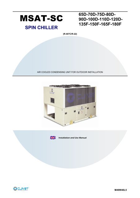
<strong>MSAT</strong>-<strong>SC</strong>SPIN CHILLER65D-70D-75D-80D-90D-100D-110D-120D-135F-150F-165F-180F(R-407C/R-22)AIR COOLED CONDENSING UNIT FOR OUTDOOR INSTALLATIONInstallation and Use ManualM49W40L5
- CONTENT -- GENERAL - ..................................................................................................................................................... 4GENERAL WARNINGS ...................................................................................................................................................4INTENDED USE ..............................................................................................................................................................4ADDITIONAL SAFETY PRECAUTIONS..........................................................................................................................4- REGULATIONS AND CERTIFICATIONS - .................................................................................................... 5UNI EN ISO 9001 CERTIFICATION ................................................................................................................................5CE MARK.........................................................................................................................................................................5EUROVENT CERTIFICATION.........................................................................................................................................5- RESIDUAL RISKS - ........................................................................................................................................ 6REFRIGERANT SAFETY CHARTS.................................................................................................................................7- TECHNICAL DATA - ..................................................................................................................................... 10GENERAL TECHNICAL SPECIFICATIONS..................................................................................................................10OPERATING LIMITS .....................................................................................................................................................12SETTING THE CUT-OUT DEVICE AND CONTROLS...................................................................................................13SOUND LEVELS ...........................................................................................................................................................13- RECEPTION/POSITIONING - ....................................................................................................................... 14INSPECTION UPON RECEPTION................................................................................................................................14STORAGE .....................................................................................................................................................................14HANDLING ....................................................................................................................................................................14REMOVING THE PACKING ..........................................................................................................................................14HOISTING USING A CRANE OR SIMILAR...................................................................................................................14FUNCTIONAL CLEARANCES.......................................................................................................................................14POSITIONING ...............................................................................................................................................................15DIMENSIONS/WEIGHT DISTRIBUTION.......................................................................................................................16- REFRIGERANT PIPES - ............................................................................................................................... 19- ELECTRICAL CONNECTIONS - .................................................................................................................. 21GENERAL......................................................................................................................................................................21LINE OF UNIT POWER SUPPLY ..................................................................................................................................21SIGNALS / DATA LINES................................................................................................................................................21STANDARD UNIT ELECTRICAL DATA ........................................................................................................................21- START-UP -................................................................................................................................................... 24- CONTROL - ................................................................................................................................................... 27- ROUTINE MAINTENANCE -......................................................................................................................... 31- TROUBLESHOOTING - ................................................................................................................................ 33- DECOMMISSIONING OF THE UNIT -.......................................................................................................... 35DI<strong>SC</strong>ONNECTING THE UNIT .......................................................................................................................................35DISMANTLING AND DISPOSAL ...................................................................................................................................35The data contained in this bulletin is not binding and may be changed by the manufacturer without prior notice.All reproduction, even partial, is prohibited.3 <strong>MSAT</strong>-<strong>SC</strong> M49W40L5
- GENERAL -- GENERAL -GENERAL WARNINGSThis manual has been designed to enable the unit to be installed, started up and maintained correctly, making it essentialto observe the following points:these instructions should be read carefully;the unit must be installed, tested and maintained by expert personal who meet the relevant legal requirements (Italianlaw No. 46 of 5/3/1990).The manufacturer declines all liability for any electrical and/or mechanical changes to the unit, which also invalid itsguarantee. Any operations whatsoever that have not been expressly authorised and do not respect the information in thismanual shall invalidate the guarantee.Observe the local safety regulations in force when installing the unit.Make sure the power supply conforms to the data on the unit’s rating plate, located inside the door of the main electricalpanel.This manual and the unit’s wiring diagram should be carefully stored so that they are readily available to the operatorwhen required.The packaging material (plastic bags, polystyrene foam, nails, etc.) is potentially dangerous and should therefore be keptaway from children and recycled in compliance with the local regulations in force.The unit must only be used for the specific purpose it was designed, as described in the paragraph GENERALTECHNICAL SPECIFICATIONS Any use other than that specified does not imply any commitment or constraint by themanufacturer in any way whatsoever.Switch off the unit in the event of faults or poor operation.Only have repairs carried out by a service centre authorised by the manufacturer, and insist on the use of original spareparts only. Failure to comply with the above may compromise the safety of the unit.The manufacturer declines all liability for any damage that may be caused whether directly or indirectly to persons orthings if these instructions are not heeded.INTENDED USEThe unit is designed for civil air-conditioning in conjunction with direct expansion gas condensation terminal units, withinthe limits defined in the technical bulletin and this manual.ADDITIONAL SAFETY PRECAUTIONSThis unit has been especially designed and manufactured so to prevent any risk to persons and health hazard.For this reason, design solutions fit to eliminate (where possible) any cause of risk and sensibly reduce the probability ofdanger have been adopted.Please refer to the "Residual Risks" section of this manual and strictly observe the behaviour prescriptions listed there inorder to prevent any possible risk that hasn’t been possible to avoid in the design stage.4 <strong>MSAT</strong>-<strong>SC</strong> M49W40L5
- REGULATIONS AND CERTIFICATIONS -- REGULATIONS AND CERTIFICATIONS -UNI EN ISO 9001 CERTIFICATIONISO 9001 : 2000ISO 9001 CERTIFIED QUALITY SYSTEMClivet S.p.A., in order to guarantee customer satisfaction, has chosen the ISO9001 Quality System as the reference for all its business activities. This isdemonstrated by the company’s commitment to ongoing improvements in thequality and reliability of its products; its sales, design, purchasing, productionand after-sales service activities are the means used to reach such purposeCE MARKClivet products bear the CE mark, in compliance with the requirements of thefollowing EC directives, including the latest amendments, and with thecorresponding national approximated legislation:- 98/37/CE- 89/336/CEE as modified by the directives 92/31/CEE and 93/68/CEE- 73/23/CEE as modified by the directive 93/68/CEE- 97/23/CEEUROVENT CERTIFICATIONClivet is partecipating in the EUROVENT Certification Programme. Products arelisted in the EUROVENT Directory of Certified Products and in the sitewww.eurovent-certification.com.5 <strong>MSAT</strong>-<strong>SC</strong> M49W40L5
- RESIDUAL RISKS -- RESIDUAL RISKS -GENERALThis section lists some of the more common situations which, being beyond the control of the manufacturer, could be asource of risk to persons or property.DEFINITION OF DANGER AREAThe figure below highlights the area in which only authorised personnel may operate.- External danger zone, identified by a precise area around the unit and its vertical projection on the ground in the case ofhanging unit.- Internal danger zone, identified by the area that can be entered only after having intentionally removed the protectingpanels or parts of these.HANDLING- If handling operations are undertaken without adopting all the necessary safety procedures and exercising due care,the unit can fall or topple, causing damage — possibly extremely serious — to persons and/or property, and to the unititself. Ensure the unit is handled and manoeuvred as directed on the packing and in the present manual, and inaccordance with local regulations. In the event of refrigerant gas escaping, refer to the “Safety datasheet” for theparticular refrigerant.INSTALLATION- Incorrect installation of the unit can result in water leaks, accumulation of condensate, escape of refrigerant, electricshocks, fire, as well as irregular operation or damage to the unit itself. Make certain that the installation is carried out onlyby a qualified technician, also that the directions contained in this manual are followed and local statutory regulationsobserved.- In the event of the unit being installed in a site where there is even the slightest risk of inflammable gas escapes andconsequently the possibility of such gases accumulating in area around the unit, the risk of explosion and fire cannot bediscounted. Take every care and precaution when selecting the installation site.- Installation on a structure not able to bear the weight and/or afford a secure anchorage of the equipment may cause theunit to fall and/or topple, resulting in damage to persons or property, or to the unit itself. Make certain that every care andprecaution is taken when positioning and securing the unit.- If the unit is easily accessible to children, unauthorized persons or animals, this is a situation that can give riseaccidents and injuries, perhaps serious. Install the unit in a place where access is allowed only to authorized persons, orinstall barriers or guards preventing unauthorized entry.GENERAL RISKS- A smell of burning, smoke or other indications of serious irregularity could signal the onset of situations liable to causedamage to persons or property or to the unit itself. Isolate the unit from the electrical power supply (red-and-yellowswitch), and contact an authorized service centre so that the source of the problem can be identified and remedied.- Accidental contact with heat exchange coils, compressors, pressure pipelines or other components can result inwounding or burns, or both. Always wear suitable clothing, including protective gloves, when working in the danger area.- Maintenance or repairs carried out by unskilled operatives can result in harm or damage to persons and property, or tothe unit itself. Always contact an authorized service centre.- Failure to close the panels of the unit, or to check that all the fixing screws of the panels are properly tightened, canresult in harm or damage to persons or property, or to the unit itself. Verify periodically that all panels are closed andmade properly secure.- In the event of fire, the temperature of the refrigerant can rise to the point that pressure will exceed safety levels andperhaps cause fluid to be projected. It may also happen that parts of the circuit isolated by closed valves will explode. Donot stand near safety valves, and never leave the valves of the refrigerant circuit closed.ELECTRICAL SYSTEM- If the power line connecting the unit to the a.c. supply is incomplete, or if the connection is made with cables of incorrectcross section and/or with insufficiently rated protective devices, this can result in electric shock, toxicity hazard, damageto the unit or fire. All work on the electrical system should be carried out referring to the wiring diagram and to thedirections given in this manual, and the system itself must be dedicated.6 <strong>MSAT</strong>-<strong>SC</strong> M49W40L5
- RESIDUAL RISKS -- Failure to secure the cover enclosing electrical components can lead to the infiltration of dust and water, ultimatelycausing electric shocks, damage to the unit, or fire. Always fasten the cover securely to the unit.- If live metal parts of the unit are not connected properly to the earth system, they can cause electric shock or evendeath by electrocution. Make absolutely certain that the connection to the earth system is made in accordance withcorrect practice.- Contact with live parts rendered accessible internally of the unit when the guards are removed can result in electricshock, burns or death by electrocution. Before exposing these parts, make certain the isolating switch on the power lineto the unit is set to the OFF position and padlocked, and post a warning sign.- Contact with parts that could become live when the unit is started up can result in electric shock, burns or death byelectrocution. When there is no need for circuits to be powered up, set the isolating switch on the power line to the OFFposition, padlock it and post a warning sign.MOVING PARTS- Contact with the fan rotors can cause injury. Before removing the protective grilles or the fans themselves, make certainthe isolating switch on the power line to the unit is set to the OFF position and padlocked, and post a warning sign.- Contact with the fan rotors can cause injury. Before removing the protective grilles or the fans themselves, make certainthe isolating switch on the power line to the unit is set to the OFF position and padlocked, and post a warning sign.REFRIGERANT- In the event of safety valves coming into operation and releasing refrigerant gas, persons in the vicinity can be injuredor suffer toxic effects. Always wear suitable clothing and protective goggles when working in potential hazard areas. Inthe event of refrigerant gas escaping, refer to the “Safety datasheet” for the particular refrigerant.- If an open flame or heat source is brought into contact with the refrigerant, or the pressurized gas circuit shouldoverheat (e.g. during welding operations), this can cause explosion or fire. Do not position any heat source within thehazard area. Maintenance or repair operations involving welding must be carried out with the system emptied ofrefrigerant.WATER SYSTEM- Defects affecting pipelines, connections or valves and other control componentry can result in water being leaked orsprayed from the system, occasioning damage to property or causing short circuits in the unit. Make certain all hydraulicconnections are securely made, following the directions given in the present manual.REFRIGERANT SAFETY CHARTS01 Identifying elements forthe substance02 Information concerningcomposition ofcomponentsProduct name: forane 407CN°SDS 01965/1Supplier: ELF ATOCHEM ITALIAVia G.Murat 17, 20159 Milano tel. 02/668111Chemical nature of the compoundMixture based on:Forane 32(difluoromethane) (N° CAS: 75-10-5)Forane 125 (pentafluoroethan) (N° CAS: 354-33-6)Forane 134a (1.1.1.2 tetrafluoroethan) (N° CAS: 811-97-2)03 Identification of risk Greatest physical and chemical dangers:Thermal decomposition in toxic and corrosive products04 First-aid measures General information:Inhalation: Carry the victim into the open air. Resort to oxygen orartificial respiration if necessary.Contact with skin: Frostbite must be treated in the same way asburns.Contact with the eyes: Immediate rinsing in abundant water. Ifirritation should continue, consult an ophthalmologist.Instructions for the physician: Do not administercatecolammine (due to the cardiac sensitisation provoked by theproduct)05 Fire prevention measures Specific dangers: Thermal decomposition into toxic andcorrosive products. Hydrofluoric acid. Carbon oxides.Specific means of intervention: Cool containers/cisterns withjets of water. Prevent any sparks or flames.Do NOT smoke.Special protection systems for fire-fighting squads: Carrybreathing apparatus and wear protective clothing06 Measures to take in caseof accidental spillageIndividual precautions: Avoid contact with the skin, eyes andinhalation of vapours. Use personal protection means.In an enclosed space: ventilate or use breathing apparatus (riskof anoxia). NO SMOKING ALLOWEDEnvironment protection precautions: limit waste intoenvironment with the greatest care.Product name: forane 22N°SDS 0005/7Supplier: ELF ATOCHEM ITALIA4 cours Michelet Cedex 42, 92091 Paris, France.Tel: 00331 49.00.80.80Chemical nature of the compoundMixture based on:Chlorodifluoromethane halogenated hydrocarbonN° CAS 75-45-6EINECS 200-871-9Effects on health: practically non-toxicGreatest physical and chemical dangers:Thermal decomposition in toxic and corrosive productsSpecific dangers/EEC: Dangerous for the ozone layer.General information:Inhalation: Carry the victim into the open air. Resort to oxygen orartificial respiration if necessary.Contact with skin: Frostbite must be treated in the same way asburns.Contact with the eyes: Immediate rinsing in abundant water. Ifirritation should continue, consult an ophthalmologist.Specific dangers: Thermal decomposition into toxic andcorrosive products. Hydrofluoric acid. Hydrochloric acid ingaseous form. Phosgene Carbon monoxides (CO).Specific means of intervention: Cool containers/cisterns withjets of water. Prevent any sparks or flames.Do NOT smoke.Special protection systems for fire-fighting squads: Carrybreathing apparatus and wear protective clothing.Individual precautions: Avoid contact with the skin, eyes andinhalation of vapours.In an enclosed space: ventilate or use breathing apparatus (riskof suffocation). NO SMOKING ALLOWED.Remove all risk of sparks or flames.7 <strong>MSAT</strong>-<strong>SC</strong> M49W40L5
- RESIDUAL RISKS -07 Manipulation and storage Technical measures/precautions.Form of storage and manipulation applicable to the products:PRESSURIZED GAS.Ensure adequate ventilation and evacuation for the level ofequipment.Advice for use: Prevent sparks and contact with hot surfaces.DO NOT SMOKE.Technical measures/Storage procedures: Store at roomtemperature in the original container. Keep away from flames, hotsurfaces and sparks. Store in a cool, well-ventilated place.Protect full containers from sources of heat to avoid excessivepressures.Recommended: Ordinary steel.Avoid: Alloy containing more than 2% magnesium.Plastics.08 Control of individualexposure/protection09 Physical and chemicalpropertiesPrecautionary measures to be taken: Ensure a sufficientexchange of air and/or suction in workplaces.Control parameters.Exposure limits: No limit value F-USAForane 134a recommended limit value by Elf : VME=1000ppmForane 32 recommended limit value by Elf : VME=1000ppmForane 125 recommended limit value by Elf : VME=1000ppmIndividual protective equipment:Respiratory protection: In case of insufficient ventilation, carrysuitable breathing apparatus.Protection for the hands: GlovesProtection for the eyes: Protective eyewearPhysical state (20°C): liquid gasColour: colourlessSmell: Slightly similar to ether; pH: not applicable.Boiling point/interval: -42,4 °CFlash point: No flare up at test conditionsVapour pressure: (25°C): 1.13 Mpa (11,3 bar) a (50°C): 2.11Mpa (21,1 bar) a (70°C): 3.26 Mpa (32,6 bar)Vapour density: At boiling point 4,54 kg/m3Density: (25°C) 1133 kg/m3 a (50°C) 1004 kg/m3 a (70°C) 861kg/m310 Stability and reactivity Conditions to avoid: Avoid contact with flames and red-hotmetal surfaces.Dangerous decomposition products: Thermal decompositioninto toxic and corrosive products: (hydrofluoric acid)Other Information: Stable product at normal storage andhandling conditions11 Toxicological information Inhalation: In experiments on animals Forane 134a, 32, 125practically non-toxic. No mortality noticed on rats at 500000ppm/4h. As with other volatile aliphatic halogenated compounds,with the accumulation of vapours and/or the inhalation of largequantities, the product can cause: loss of consciousness andheart problems aggravated by stress and lack of oxygen; risk ofdeath.Contact with skin: Frostbite possible from splashes of liquefiedgas.Chronic toxicity: Studies on animal protracted inhalation do nothighlight any sub-chronic toxic effect (rat/3 month(s)/ Inhalation:50000ppm)Specifical effects: Genotoxicity according experimental availabledata Forane 134a, 32, 125 NOT GenotoxicCancerogenesis: Forane 134a: experiments on animals do nothighlight carcinogen effect clearly demonstrated (rat /Inhalation –for oral administration)Toxicity for reproduction: Foetal growth Forane 134a, 32, 125according to available data no toxic effect for foetal development.Fertility, according the limited data on animal: Forane 134a noeffects on fertility (rats/inhalation)Technical measures/precautions.Form of storage and manipulation applicable to the products:PRESSURIZED GAS.Ensure adequate ventilation and evacuation for the level ofequipment.Advice for use: Prevent sparks and contact with hot surfaces.DO NOT SMOKE.Technical measures/Storage procedures: Store at roomtemperature in the original container. Keep away from flames, hotsurfaces and sparks. Store in a cool, well-ventilated place.Protect full containers from sources of heat to avoid excessivepressures.Recommended: Ordinary steel.Avoid: Alloy containing more than 2% magnesium.Plastics.Precautionary measures to be taken: Ensure a sufficientexchange of air and/or suction in workplaces.Control parameters.Exposure limits:France 1989: VME = 1000USA 1992: TWA = 1000 p.p.m. = 3500 mg/m3Individual protective equipment:Respiratory protection: In case of insufficient ventilation, carrysuitable breathing apparatus.Protection for the hands: GlovesProtection for the eyes: Protective eyewear.Specific hygiene measures: avoid contact with the skin, eyes andinhalation of the vapours.Physical state (20°C): liquid gasColour: colourlessSmell: Slightly similar to ether; pH: not applicable.Boiling point/interval: -40.8 °CMelting point/interval: -160 °CDecomposition temperature: 480 °CVapour pressure: (20 °C) 0.91 Mpa (9.1 bar); at 50 °C: 1.91Mpa (19.4 bar)Vapour density: (20° C) 3.57 kg/m3Solubility: water (25 °C) 3g/l - solvent soluble in hydrocarbonsand chlorinated solvents, alcohols, ketones, esters.Solubility of water in the product at 30° C: 0.15% in weight.Conditions to avoid: Avoid contact with flames and red-hotmetal surfaces.Dangerous decomposition products: Thermal decompositioninto toxic and corrosive products: hydrofluoric acid, hydrochloricacid in gaseous form, phosgene, carbon monoxide (CO)Inhalation: Practically non-toxic in experiments conducted onanimals. No effect below 50,000 p.p.m.As with other volatile aliphatic halogenated compounds, with theaccumulation of vapours and/or the inhalation of large quantities,the product can cause: loss of consciousness and heart problemsaggravated by stress and lack of oxygen; risk of death.Contact with skin: Frostbite possible from splashes of liquefiedgas.Contact with the eyes: <strong>Temp</strong>orary irritation.8 <strong>MSAT</strong>-<strong>SC</strong> M49W40L5
- RESIDUAL RISKS -12 Ecological information Forane 32 ,Durability/degradability: Not easily biodegradable in water 5%after 28dBioaccumulation: Practically non-absorbable by biologicalorganisms log pow 0,21Forane 125Mobility: Rapid evaporation t ½ life 3,2 h (estimate)Durability/degradability: Not easily biodegradable in water 5%after 28d. In the troposphere degradation at rate t ½ life 28,3 y(estimate). Potential for destruction of ozone ODP (R-11 = 1)=0.Potential greenhouse effect (GWP): (HGWP) = 0,58. Lowabsorption in ground and sediments log Koc= 1,3-1,7Bioaccumulation: Practically non-absorbable by biologicalorganisms log pow 1,48Forane 134aMobility: Rapid evaporation t ½ vita 3 h (estimate)Durability/degradability: Not easily biodegradable in water 3%after 28d. 28d. In the atmosphere degradation at rate 3% after28d . Potential for destruction of ozone ODP (R-11 = 1)=0.Potential greenhouse effect (GWP) 0,26.Bioaccumulation: Practically non-absorbable by biologicalorganisms log pow 1,0613 Notes concerning Disposal of product: recycle or incinerate.disposal14 Information on shipping Call ELF ATOCHEM safety services for updating and moreinformation.ONU Number 3163. RID\ADR class 2 figure (and letter) 4°aPrescriptions: Labels 2 N° danger /N° material 20/3163IMDG class 2.2 N°ONU (IMDG) 3163Prescriptions: Labels 2.2IATA class 2.2 N°ONU (IATA) or N°ID3163Prescriptions: Labels 2.215 Information on regulation EEC directivesSecurity reports: D.91/155/EEC modified by D.93/112/EEC:Dangerous substancesEEC classification and labellingDangerous preparation: Not classified as dangerousInventory: in accordance with EINECS16 Other information Recommended uses: Refrigerant fluidBibliographical references: Encyclopedie des gas (Air Liquideed.1976-ELSEVIER AMSTERDAM)Mobility: Rapid evaporation: 1/2 life 2.7 h.Durability/degradability: Not easily biodegradable in water: 0%after 28 days. In the atmosphere degradation at rate of 1/2 life in14 years. Potential for destruction of ozone ODP (R-11 = 1) =0.055. Potential greenhouse effect (HGWP) - 0.36. Lowabsorption in ground and sediments log Koc = 1.8.Bioaccumulation: Practically non-absorbable by biologicalorganisms: log pow 1.08.Aquatic toxicity: Acute toxicity, level of toxicity for fish over 24hours = 180 mg/l; for anaerobic bacteria, level of toxicity over 24hours > 400 mg/l.Disposal of product: recycle.ONU number 1018. RID/ADR class 2 figure (and letter) 3° aRegulations: No. danger/No. material 20/1018 label 2IMDG class 2.2 ONU (IMDG) 1018Regulations: NON INFLAMMABLE GAS/2 labelIATA class 2.2 ONU (IATA) or No.ID1018Regulations: NON INFLAMMABLE GAS/2 labelProduct code: 00055/7EEC directivesSecurity reports: D.91/155/EEC modified by D.93/112/EEC:Dangerous substances and manufactured compoundsDangerous manufactured compounds: D.67/548/CEE modifiedby D.93/21/CEE: Guide to labelling (18th APT).R59 Dangerous for the ozone layer S59 Consultproducer/supplier for information concerning recovery andrecycling.S61 Do not dump. Consult specific instructions and safetyinformation.Recommended uses: low-temperature coolant, Freezing agent,Air conditioning.Bibliographical references: Encyclopédie des gas (Air liquideed.1976 - ELSEVIER AMSTERDAM).INRS toxicological report: No. 142CHLOROFLUOROMETHANEThis document refers to the product as is and which conforms to the specifications supplied by ELF ATOCHEM.If combinations or mixtures are made, check that there are no new dangers resulting from this action. The informationprovided in this report has been provided in good faith and is based on our latest knowledge of the product in question asof the date of publication of the same. The attention of users is drawn to the potential risks of employing the product forany use other than that for which it is intended. This report must be used and reproduced solely for purposes ofprevention and safety. The list of legislative, regulatory or administrative texts must not be considered exhaustive. Theproduct user is under obligation to refer to all the official texts concerning the use, conservation and manipulation of theproduct for which he is sole responsible. The product user must also provide all those who might come into contact withthe product with the information necessary for their safety at work and the protection of their health and that of theenvironment, giving them a copy of this safety information report.9 <strong>MSAT</strong>-<strong>SC</strong> M49W40L5
- TECHNICAL DATA -- TECHNICAL DATA -GENERAL TECHNICAL SPECIFICATIONSACOUSTIC CONFIGURATION: COMPRESSORS SOUNDPROOFING (<strong>SC</strong>)Sizes 65D 70D 75D 80D 90D 100D 110D 120D 135F 150F 165F 180FCooling R-407CCooling capacity (1) kW 210.3 226.2 240.5 254.8 277.6 318.0 363.5 386.4 428.8 462.1 518.3 587.9Compressor absorbed power kW 56.5 61.2 67.6 73.9 81.2 88.5 99.5 113.8 124.2 140.1 156.8 171.6Total absorbed power (2) kW 64.8 69.5 75.9 82.2 89.5 96.8 111.9 126.2 138.5 156.4 178.6 193.4EER Nr 3.25 3.25 3.17 3.10 3.10 3.29 3.25 3.06 3.10 2.95 2.90 3.04Cooling R-22Cooling capacity (3) kW 203 218.2 232.1 245.9 268.5 307.2 351.4 373.8 414.3 446.7 501.5 569.3Compressor absorbed power kW 50.5 54.7 60.2 65.7 72.4 78.9 88.7 101.4 110.6 124.9 139.7 152.9Total absorbed power (2) kW 58.8 63 68.5 74 80.7 87.2 101.1 113.8 124.9 141.2 161.5 174.7EER Nr 3.45 3.46 3.39 3.32 3.33 3.52 3.47 3.28 3.32 3.16 3.11 3.26CompressorCompressor typeScrollN° of compressor nr 4 4 4 4 4 4 4 4 6 6 6 6Nominal power (C1) HP 30 35 35 40 45 50 55 60 60 75 75 90Nominal power (C2) HP 35 35 40 40 45 50 55 60 75 75 90 90Capacity control steps Std nr 4 4 4 4 4 4 4 4 6 6 6 6Oil charge (C1) kg 12 14 14 16 16 16 19 24 24 24 24 24Oil charge (C2) kg 14 14 16 16 16 16 24 24 24 24 24 24MANEUROP compressors SZ type (use only R-407C): POE 160 SZOil typeMANEUROP compressors SY type (R-22 and R-407C): POE 320 SZCOPELAND compressors: POE Copeland 3MA (32 cSt)Refrigerant circuits Nr 2 2 2 2 2 2 2 2 2 2 2 2External exchangerFront surface m 2 11,9 11,9 11,9 11,9 11,9 11,9 17,3 17,3 17,3 17,3 17,3 17,3External section fanType of fansAxialN° of fans Nr 2 + 2 2 + 2 2 + 2 2 + 2 2 + 2 2 + 2 3 + 3 3 + 3 3 + 4 4 + 4 4 + 4 4 + 4Standard air flow rate l/s 24400 23900 23900 23900 23900 23900 36700 35750 39700 43600 46000 44800ConnectionsGas connections “ 42+54 54+54 54+54 54+54 54+54 54+54 64+64 64+64 64+64 64+64 64+76 76+76Liquid connections “ 22+28 28+28 28+28 28+28 28+28 35+35 35+35 35+35 35+35 35+35 35+42 42+42VoltageStd voltage V 400/3/50DimensionsLength mm 2950 2950 2950 2950 2950 2950 4250 4250 4250 4250 4250 4250Depth mm 2195 2195 2195 2195 2195 2195 2195 2195 2195 2195 2195 2195Height mm 2410 2410 2410 2410 2410 2410 2410 2410 2410 2410 2410 2410Standard unit weightShipping weight kg 2032 2092 2152 2212 2217 2214 2690 2863 2988 3070 3378 3570Operation weight kg 2102 2164 2226 2288 2293 2298 2805 2983 3113 3200 3508 3700(1) data referred to the following conditions :saturated suction temperature (SST) = 9.5 °C (Dew Point)outside air temperature 35°C(2) Total absorbed power is given by the compressor absorbed power + fan absorbed power + auxiliary circuit absorbedpower.(3) data referred to the following conditions:saturated suction temperature (SST) = 7,5°Coutside air temperature 35°C10 <strong>MSAT</strong>-<strong>SC</strong> M49W40L5
- TECHNICAL DATA -ACOUSTIC CONFIGURATION: EXTREMELY LOW NOISE (EN)Sizes 65D 70D 75D 80D 90D 100D 110D 120D 135F 150F 165F 180FCooling R-407CCooling capacity (1) kW 204,1 219,7 230,7 243,9 264,4 299,6 350,3 379,3 405,5 449,6 500,4 551,2Compressor absorbed power kW 58,4 64,2 71,8 78,7 86,8 97,3 103,4 117,5 131,7 145,8 165,5 185,2Total absorbed power (2) kW 63,7 69,5 77,1 84,0 92,1 102,6 111,3 125,4 140,8 159,3 179,3 199,0EER Nr 3,20 3,16 2,99 2,90 2,87 2,92 3,15 3,02 2,88 2,82 2,79 2,77Cooling R-22Cooling capacity (3) kW 197.3 212.4 223.2 235.9 256.7 289.9 339.1 367.9 392.2 435 484.9 534.8Compressor absorbed power kW 52.1 57.1 63.8 69.8 77.2 86.7 92.1 104.6 117.1 130 147.3 164.5Total absorbed power (2) kW 57.4 62.4 69.1 75.1 82.5 92 100 112.5 126.2 143.5 161.1 178.3EER Nr 3.44 3.4 3.23 3.14 3.11 3.15 3.39 3.27 3.11 3.03 3.01 3CompressorCompressor typeScrollN° of compressor nr 4 4 4 4 4 4 4 4 6 6 6 6Nominal power (C1) HP 30 35 35 40 45 50 55 60 60 75 75 90Nominal power (C2) HP 35 35 40 40 45 50 55 60 75 75 90 90Capacity control steps Std nr 4 4 4 4 4 4 4 4 6 6 6 6Oil charge (C1) kg 12 14 14 16 16 16 19 24 24 24 24 24Oil charge (C2) kg 14 14 16 16 16 16 24 24 24 24 24 24MANEUROP compressors SZ type (use only R-407C): POE 160 SZOil typeMANEUROP compressors SY type (R-22 and R-407C): POE 320 SZCOPELAND compressors: POE Copeland 3MA (32 cSt)Refrigerant circuits Nr 2 2 2 2 2 2 2 2 2 2 2 2External exchangerFront surface m 2 11,9 11,9 11,9 11,9 11,9 11,9 17,3 17,3 17,3 17,3 17,3 17,3External section fanType of fansAssialeN° of fans Nr 4 4 4 4 4 4 6 6 7 8 8 8Standard air flow rate l/s 18200 17800 17800 17800 17800 16900 26550 26550 32500 35000 34200 33350ConnectionsGas connections “ 42+54 54+54 54+54 54+54 54+54 54+54 64+64 64+64 64+64 64+64 64+76 76+76Liquid connections “ 22+28 28+28 28+28 28+28 28+28 35+35 35+35 35+35 35+35 35+35 35+42 42+42VoltageStd voltage V 400/3/50DimensionsLength mm 2950 2950 2950 2950 2950 2950 4250 4250 4250 4250 4250 4250Depth mm 2195 2195 2195 2195 2195 2195 2195 2195 2195 2195 2195 2195Height mm 2410 2410 2410 2410 2410 2410 2410 2410 2410 2410 2410 2410Standard unit weightShipping weight kg 2042 2112 2172 2232 2237 2234 2710 2888 3078 3170 3468 3570Operation weight kg 2112 2184 2246 2308 2313 2318 2825 3008 3203 3300 3598 3720(1) data referred to the following conditions :saturated suction temperature (SST) = 9.5 °C (Dew Point)outside air temperature 35°C(2) Total absorbed power is given by the compressor absorbed power + fan absorbed power + auxiliary circuit absorbedpower.(3) data referred to the following conditions:saturated suction temperature (SST) = 7,5°Coutside air temperature 35°C11 <strong>MSAT</strong>-<strong>SC</strong> M49W40L5
OPERATING LIMITS- TECHNICAL DATA -R-407CACOUSTIC CONFIGURATION: COMPRESSORS SOUNDPROOFING (<strong>SC</strong>)Sizes 65D 70D 75D 80D 90D 100D 110D 120D 135F 150F 165F 180FExternal exchangerMax air intake temperature 1 °C 45 45 43 43 42 42 42 42 41 41 41 41Max air intake temperature 2 °C 48 48 46 46 45 45 45 45 44 44 44 44Min. air intake temperature 3 °C -10 -10 -10 -10 -10 -10 -10 -10 -10 -10 -10 -10Min. air intake temperature 4 °C -7 -7 -7 -7 -7 -7 -7 -7 -7 -7 -7 -7Min. air intake temperature 5 °C 3 3 3 3 3 3 3 3 3 3 3 3Min. air intake temperature 6 °C 13 13 13 13 13 13 13 13 13 13 13 13CompressorMax saturated suction temperature (SST) °C 15 15 15 15 15 15 15 15 15 15 15 15ACOUSTIC CONFIGURATION: EXTREMELY LOW NOISE (EN)Sizes 65D 70D 75D 80D 90D 100D 110D 120D 135F 150F 165F 180FExternal exchangerMax air intake temperature 1 °C 43 43 41 41 40 40 41 40 40 40 39 39Max air intake temperature 2 °C 46 46 44 44 43 43 44 43 43 43 42 42Min. air intake temperature 3 °C -10 -10 -10 -10 -10 -10 -10 -10 -10 -10 -10 -10Min. air intake temperature 4 °C -7 -7 -7 -7 -7 -7 -7 -7 -7 -7 -7 -7Min. air intake temperature 5 °C 3 3 3 3 3 3 3 3 3 3 3 3Min. air intake temperature 6 °C 13 13 13 13 13 13 13 13 13 13 13 13CompressorMax saturated suction temperature (SST) °C 15 15 15 15 15 15 15 15 15 15 15 15saturated suction temperature (SST) = 9.5 °C (Dew Point)Warning: the still air condition is meant as absence of air flow to the unit. Any wind condition can let air pass through the condenser coilthus worsening the operating limits of the unit (see limits with air speed at 0,5 m/s & 1 m/s). In order to avoid such situation, windbreakbarriers are necessary.(1) unit at full load(2) capacity-controlled unit (automatic capacity control)(3) unit at full load external exchanger air in quietR-22(4) capacity-controlled unit (automatic capacity control)external exchanger air in quiet(5) capacity-controlled unit (automatic capacity control)air to external exchanger = 0.5m/sec(6) capacity-controlled unit (automatic capacity control)air to external exchanger = 0.5m/secACOUSTIC CONFIGURATION: COMPRESSORS SOUNDPROOFING (<strong>SC</strong>)Sizes 65D 70D 75D 80D 90D 100D 110D 120D 135F 150F 165F 180FExternal exchangerMax air intake temperature 1 °C 47 47 45 45 44 44 44 44 43 43 43 43Max air intake temperature 2 °C 50 50 48 48 47 47 47 47 46 46 46 46Min. air intake temperature 3 °C -10 -10 -10 -10 -10 -10 -10 -10 -10 -10 -10 -10Min. air intake temperature 4 °C -7 -7 -7 -7 -7 -7 -7 -7 -7 -7 -7 -7Min. air intake temperature 5 °C 3 3 3 3 3 3 3 3 3 3 3 3Min. air intake temperature 6 °C 13 13 13 13 13 13 13 13 13 13 13 13CompressorMax saturated suction temperature (SST) °C 15 15 15 15 15 15 15 15 15 15 15 15ACOUSTIC CONFIGURATION: EXTREMELY LOW NOISE (EN)Sizes 65D 70D 75D 80D 90D 100D 110D 120D 135F 150F 165F 180FExternal exchangerMax air intake temperature 1 °C 45 45 43 43 42 42 43 42 42 42 41 41Max air intake temperature 2 °C 48 48 46 46 45 45 46 45 45 45 44 44Min. air intake temperature 3 °C -10 -10 -10 -10 -10 -10 -10 -10 -10 -10 -10 -10Min. air intake temperature 4 °C -7 -7 -7 -7 -7 -7 -7 -7 -7 -7 -7 -7Min. air intake temperature 5 °C 3 3 3 3 3 3 3 3 3 3 3 3Min. air intake temperature 6 °C 13 13 13 13 13 13 13 13 13 13 13 13CompressorMax saturated suction temperature (SST) °C 15 15 15 15 15 15 15 15 15 15 15 15saturated suction temperature (SST) = 9.5 °C (Dew Point)Warning: the still air condition is meant as absence of air flow to the unit. Any wind condition can let air pass through the condenser coilthus worsening the operating limits of the unit (see limits with air speed at 0,5 m/s & 1 m/s). In order to avoid such situation, windbreakbarriers are necessary.(1) unit at full load(2) capacity-controlled unit (automatic capacity control)(3) unit at full load external exchanger air in quiet(4) capacity-controlled unit (automatic capacity control)external exchanger air in quiet(5) capacity-controlled unit (automatic capacity control)air to external exchanger = 0.5m/sec(6) capacity-controlled unit (automatic capacity control)air to external exchanger = 0.5m/sec12 <strong>MSAT</strong>-<strong>SC</strong> M49W40L5
- TECHNICAL DATA -SETTING THE CUT-OUT DEVICE AND CONTROLSOn Off ValueHigh pressure safety switch kPa 2700 1940 --Low pressure safety switch - Standard version kPa 230 360 --High pressure safety valve kPa -- -- 3000Low pressure safety valve kPa -- -- 1900Max compressor starts per hour Nr -- -- 10Safety discharge thermostat °C -- -- 120SOUND LEVELSACOUSTIC CONFIGURATION:COMPRESSORS SOUNDPROOFING (<strong>SC</strong>)EXTREMELY LOW NOISE (EN)Sound Power Level (dB)Sound SoundSound SoundSound Power Level (dB)pressure powerpressure powerOctave band (Hz) level level Octave band (Hz) level levelSize 63 125 250 500 1000 2000 4000 8000 dB(A) dB(A) Size 63 125 250 500 1000 2000 4000 8000 dB(A) dB(A)65D 99 95 96 92 88 84 77 71 76 94 65D 88 91 87 83 80 75 69 62 67 8570D 99 95 95 92 88 84 77 70 76 94 70D 88 91 87 83 80 75 69 62 68 8675D 99 95 95 92 88 84 77 70 76 94 75D 88 91 87 84 80 75 69 62 68 8680D 99 95 95 92 88 84 77 70 76 94 80D 88 91 87 85 80 75 69 62 68 8690D 99 95 95 92 88 84 77 70 76 94 90D 88 91 87 84 80 75 70 62 68 86100D 99 95 96 92 88 84 77 70 76 94 100D 87 90 87 85 80 75 70 61 68 86110D 101 97 98 94 90 86 79 73 78 96 110D 90 93 89 86 82 77 71 64 70 88120D 100 98 98 95 91 86 80 73 78 97 120D 90 93 89 87 82 77 71 64 70 88135F 101 98 99 95 91 87 80 74 78 97 135F 92 95 91 87 84 78 72 66 71 89150F 102 98 99 96 92 87 81 74 78 97 150F 93 96 92 88 84 79 72 67 71 90165F 102 99 100 96 92 88 81 75 79 98 165F 92 95 92 89 85 80 74 66 72 91180F 102 99 99 96 92 88 81 74 79 98 180F 92 95 92 90 84 80 74 66 72 91Measures according to ISO 3744 regulations, with respect to the EUROVENT 8/1 certification.The sound levels refer to the unit at full load, in the rated test conditions.The sound pressure level refers to a distance of 1m from the external surface of the units operating in an open field.Data referred to the following conditions :saturated suction temperature (SST) = 9.5 °C (Dew Point)outside air temperature 35°C13 <strong>MSAT</strong>-<strong>SC</strong> M49W40L5
- RECEPTION/POSITIONING -INSPECTION UPON RECEPTION- RECEPTION/POSITIONING -Check on arrival that the unit has not suffered damage during transit and that it is complete in every part as specified inthe order. In the event of visible damage/deficiencies being discovered, make a note immediately on the deliverydocument with the comment: "CONDITIONAL ACCEPTANCE — CLEAR EVIDENCE OF DEFICIENCIES/DAMAGEDURING TRANSIT", then inform both the supplier and the carrier of the details by fax and by registered mail with adviceof receipt not later than 8 days after taking consignment. Notifications sent after 8 days have elapsed will be ignored.STORAGEShelter from: direct sunlight, rain, sand and wind<strong>Temp</strong>erature: maximum 60°C minimum -10°CMaximum humidity: 90%The respect of the instructions on the exterior side of the packaging assures the physical and functional integrity of theunit for the final user’s advantage.It is recommended to:Handle carefullyKeep in a dry placeAvoid putting other objects on top of the unit (respect the limits of levels of superimposition shown in the package)Avoid placing the unit with thermoretractable protection under the sun since the pressure of the circuits can assumevalues which activate the safety valves.HANDLINGThe operation of handling the unit must be carried out respecting the instructions of the safety norms in force (LegislativeDecree 626/94 and following modifications)Before starting the handling operations:Verify that the lifting capacity of the means used is adequate to the unit weightConsider that the barycentre could be moved with respect to the center of the unit.REMOVING THE PACKINGFor removing the packaging, use specific personal protection for the operator (gloves, glasses, etc.).Remove the polystyrene packaging making sure not to damage the unit..Check for any visible damage.Dispose of the packaging by taking it to specialist collection or recycling centres, in accordance with local regulations.HOISTING USING A CRANE OR SIMILARAttach the slings to the yellow lifting brackets provided.When lifting, it isabsolutely essential that a beam or other rigid spacer should be used sothat no pressure will be applied to the top part of the unit by the slingswhen under tension.Gradually bring the lifting belts under tension, making sure they arepositioned correctly. Make sure the unit is always in steady equilibrium.(refer to “Weight Distribution” for the position of the centre of gravity).Commence lifting.FUNCTIONAL CLEARANCESWhen placing the unit, please make sure that the functional clearances indicated on DIMENSIONS chapter, allow allmaintenance operations to be performed. this is required for optimum unit operation and particularly for the safety ofauthorised personnel and exposed persons.In the event of multiple units, the functional clearances must be doubled.14 <strong>MSAT</strong>-<strong>SC</strong> M49W40L5
- RECEPTION/POSITIONING -POSITIONINGThe units are designed for the exterior installation in a fixed position and in areas which can be easily reached byqualified and specialized personnel.The choice of where to position the unit is of fundamental importance for its use and working.Obstacles to the air flow , difficulties of air circulation , Leaves or other objects which can obstruct the exchange coils,winds which contrast or favor too much air flow, phenomena’s of stratification or of air circulation, sources of heat in thenearby vicinity, are cause working anomalies or stop the machine.During SUMMER usage, the increase of the condensate pressure with a drop of performances can cause blocksbecause of high pressure .In WINTER operation decrease of the evaporation pressure and increase of the number of defrosting increases with thedecay of performances and possible stops due to low pressure.Installations below ground level or near very high walls must be carefully assessed.Avoid installation in areas that may be subject to flooding.Install the unit raised from the ground, also considering the maximum level that can be reached in case of snow.During the WINTER operation, the heat pump produces a great quantity of condensation water..Verify that the condensation drain tube does not cause any problems to people or things (for example, dropping fromterraces, walking places, etc.)Check that the fastening/support points are in level and can bear the weight of the unit (see weights and weightdistribution).Place a layer of rubber between the base of the unit and the support to prevent noise and vibrations.It is recommended the use of spring antivibration mounts if steel wire netting structure are installed. The assembly onantivibration mounts, spring or rubber, requires flexible joints on all the unit connections (hydraulic, aeraulic orrefrigerant).Fasten the unit to the ground; when placing the unit where there are strong winds, foresee windbreak barriers.15 <strong>MSAT</strong>-<strong>SC</strong> M49W40L5
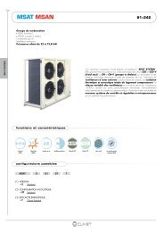
DIMENSIONS/WEIGHT DISTRIBUTIONSizes 65D-70D-75D-80D-90D-100D- RECEPTION/POSITIONING -124109 7356336 6581038352 253 5321959902 29901370 13702950187(12)15(14)1500700(11)70035785 1380 785W1W242125G5O P35W3W4(11)700MN(13)1300(1) EXTERNAL EXCHANGER (CONDENSER)(2) HOLE TO HANG UNIT(3) LIFTING BRACKETS(4) ELECTRICAL PANEL(5) POWER INPUT(6) SOUNDPROOFED CABIN(7) SUCTION LINE CONNECTION C1(8) LIQUID LINE CONNECTION C1(9) SUCTION LINE CONNECTION C2(10) LIQUID LINE CONNECTION C2(11) MINIMUM DIMENSION FOR A SAFE PASSAGE.(12) MINIMUM DIMENSION FOR A SAFE PASSAGE WHEN THEDOOR OF THE ELECTRICAL SWITCHBOARD IS OPEN.(13) MINIMUM DIMENSION FOR A PROPER AIR FLOW TO THECONDENSER COIL.(14) MINIMUM DIMENSION ON THE ELECTRICAL SWITCHBOARDSIDE.(15) CLEARANCE ACCESS RECOMMENDED<strong>SC</strong>Sizes 65D 70D 75D 80D 90D 100D 65D 70D 75D 80D 90D 100DM mm 1437 1462 1437 1460 1460 1460 1458 1462 1437 1460 1461 1461N mm 1517 1492 1517 1494 1493 1493 1496 1492 1517 1493 1493 1493P mm 838 825 812 801 802 802 827 827 815 803 804 805Q mm 1360 1372 1385 1396 1395 1395 1370 1370 1382 1393 1393 1392W1 kg 692 695 747 750 751 752 680 700 752 755 756 757W2 kg 617 665 665 715 716 717 645 670 671 720 721 722W3 kg 420 411 430 422 423 424 404 416 435 427 428 429W4 kg 374 393 383 402 403 405 383 398 388 407 408 410Operating weight kg 2102 2164 2226 2288 2293 2298 2112 2184 2246 2308 2313 2318Shipping weight kg 2032 2092 2152 2212 2217 2214 2042 2112 2172 2232 2237 2234Particular accessories, executions or versions can bring about a great variation of the mass represented here.Please contact our Technical Department.EN16 <strong>MSAT</strong>-<strong>SC</strong> M49W40L5
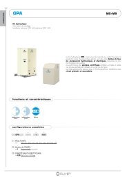
- RECEPTION/POSITIONING -Sizes 110D-120D-135F-150F1241097356 63103538683522825 22 82518753532020 202021954250(12)15(14)1500700(11)70035985 2280 985W1W242125G5O P35W3W4(11)700MN(13)1300(1) EXTERNAL EXCHANGER (CONDENSER)(2) HOLE TO HANG UNIT(3) LIFTING BRACKETS(4) ELECTRICAL PANEL(5) POWER INPUT(6) SOUNDPROOFED CABIN(7) SUCTION LINE CONNECTION C1(8) LIQUID LINE CONNECTION C1(9) SUCTION LINE CONNECTION C2(10) LIQUID LINE CONNECTION C2(11) MINIMUM DIMENSION FOR A SAFE PASSAGE.(12) MINIMUM DIMENSION FOR A SAFE PASSAGE WHEN THEDOOR OF THE ELECTRICAL SWITCHBOARD IS OPEN.(13) MINIMUM DIMENSION FOR A PROPER AIR FLOW TO THECONDENSER COIL.(14) MINIMUM DIMENSION ON THE ELECTRICAL SWITCHBOARDSIDE.(15) CLEARANCE ACCESS RECOMMENDEDSizes 110D 120D 135F 150F 110D 120D 135F 150F<strong>SC</strong>M mm 2141 2117 2112 2165 2063 2117 2112 2113N mm 2117 2140 2140 2087 2194 2140 2139 2139P mm 794 794 776 784 795 795 807 794Q mm 1404 1404 1419 1411 1403 1403 1387 1401W1 kg 893 969 1026 1001 960 977 1031 1073W2 kg 912 950 1002 1071 856 958 1007 1049W3 kg 495 537 549 545 533 542 589 596W4 kg 506 527 536 583 475 532 575 582Operating weight kg 2805 2983 3113 3200 2825 3008 3203 3300Shipping weight kg 2690 2863 2988 3070 2710 2888 3078 3170Particular accessories, executions or versions can bring about a great variation of the mass represented here.Please contact our Technical Department.EN17 <strong>MSAT</strong>-<strong>SC</strong> M49W40L5
Sizes 165F-180F- RECEPTION/POSITIONING -1241097346 6 653310383584532525382522020 2020218782521954250(12)15(14)1500700(14)170035985 2280W1W29852125G4O P35(11)700W3MNW4(13)1300700(12)(1) EXTERNAL EXCHANGER (CONDENSER)(2) HOLE TO HANG UNIT(3) LIFTING BRACKETS(4) ELECTRICAL PANEL(5) POWER INPUT(6) SOUNDPROOFED CABIN(7) SUCTION LINE CONNECTION C1(8) LIQUID LINE CONNECTION C1(9) SUCTION LINE CONNECTION C2(10) LIQUID LINE CONNECTION C2(11) MINIMUM DIMENSION FOR A SAFE PASSAGE.(12) MINIMUM DIMENSION FOR A SAFE PASSAGE WHEN THEDOOR OF THE ELECTRICAL SWITCHBOARD IS OPEN.(13) MINIMUM DIMENSION FOR A PROPER AIR FLOW TO THECONDENSER COIL.(14) MINIMUM DIMENSION ON THE ELECTRICAL SWITCHBOARDSIDE.(15) CLEARANCE ACCESS RECOMMENDEDSIZES 165F 180F 165F 180FM mm 2132 2167 2132 2166N mm 2119 2085 2119 2085O mm 789 764 776 765P mm 1406 1430 1418 1430W1 kg 1125 1171 1164 1177W2 kg 1138 1259 1178 1265W3 kg 619 612 624 616W4 kg 626 658 631 662Operating weight kg 3508 3700 3598 3720Shipping weight kg 3378 3570 3468 3570<strong>SC</strong>Particular accessories, executions or versions can bring about a great variation of the mass represented here.Please contact our Technical Department.EN18 <strong>MSAT</strong>-<strong>SC</strong> M49W40L5
- REFRIGERANT PIPES -- REFRIGERANT PIPES -The sizing of the refrigerant connection lines is of extreme importance for the system operating and reliability.The diameter of the connection between the two units is function of distances, differences in level and curve number; ithas so to be calculated by a qualified technician. Incorrect sizing may damage the compressor or affect cooling capacity.The installation of the pipes may affect the level of noise in the system.install flexible joints between the unit and the pipes.• The operations must be performed by an expert refrigerator technician• Use only a copper pipe for chiller operating• Pipes must not to be too much long and with too much curves• For a good efficiency do not perform curves with a radium too much short and avoid the pipe crushing• To allow the vacuum and charge operations install service fittings on pipes (if the unit is not fitted with taps withservice fittings)• The pipe weight has not to weigh on units but it has to be sustained by anchorage brackets• Brackets must allow the pipe thermal expansion• Install antivibration material between the brackets and the pipes so as to prevent the transmission of vibrations• Pipes must be perfectly clean (perform a cleaning with nitrogen or dry air before connecting the pipes to the twounits) and without humidity to allow a good vacuum operation.SUCTION LINEThe pipe must be always insulated.In the horizontal sections, the incline must be to the compressor to allow the oil return also at the min. charge conditions.COMPRESSOR IN THE BOTTOMIf the condensing unit is lower than the evaporating unit:• make a drain tap at the same height as evaporating coil toprevent, when the machine is off, liquid from returning tothe compressor (to avoid the drain tap, fit on the liquid linea solenoid valve, always recommended)• install a tap near the evaporating unit (to avoid that thethermostatic bulb is into contact with some liquid when theunit is off)COMPRESSOR IN THE TOPIf the condensing unit is higher than the evaporating unit:• make a tap as near as possible to the evaporating unit• make an oil tap every 6 metres of vertical riseLIQUID LINEThe liquid line must be insulated if it is exposed to the sunlight or it crosses zones with a temperature higher than theexternal one, otherwise it can be free. Avoid excessive diameters to not cause an excessive refrigerant charge.The solenoid valve avoids dangerous gas leaks when the unit is off; the installation is always recommended, above allwith pipes particularly long. It has to be positioned near the thermostatic valve.19 <strong>MSAT</strong>-<strong>SC</strong> M49W40L5
- REFRIGERANT PIPES -LIQUID RECEIVERThe liquid receiver installation is always recommended, above all when:• the connecting pipes are longer than 10 metres• the installation operates in variable climatic conditions (for example external air temperature with rangesday/night, summer/winter).The receiver must have a capacity adequate to the installation and it must be positioned near the evaporating unit.If the distance is greater than 15 metres and the compressor is located in the lower part of the system, position thereceiver near the unit with the compressor.The liquid receiver can absolve the above described functions:• it avoids the presence of gaseous freon in the expansion device.• It compensates for the charge variations in the installation when changing the operating conditions• It avoids an excessive condenser flooding with consequent condensing temperature/pressure raising if theinstallation charge is performed in anomalous climatic conditions.CHECKING FOR LEAKS• Check carefully that the condensing unit taps are closed.• Connect the pressure gauges with the service fittings (on the taps or on the connection pipes).• Pressurise with refrigerant to 250KPa.• Close the valves on the pressure gauge assembly, then disconnect the refrigerant freon bottle andsubsequently connect the nitrogen bottle.• Open the valves on the pressure gauge.• Pressurise the system with nitrogen to 1200KPa.• Carefully check all the pipes using a leak detector or other electronic instrument, with special attention to thewelds and joints in general.• If the necessary equipment is not available, make sure any parts that may give rise to refrigerant leaks (welds,joints etc.) are accessible.EXTERNAL UNITINTERNAL UNITGas tapLiquid tap20 <strong>MSAT</strong>-<strong>SC</strong> M49W40L5
- ELECTRICAL CONNECTIONS -GENERAL- ELECTRICAL CONNECTIONS -The characteristics of the electrical lines and relevant components must be determined by specialized personnel able todesign electrical installations; moreover, the lines must be in conformity with professional procedures and the regulationsin force.All electrical operations should be performed by trained personnel having the necessary requisites under law and beinginformed about the risks relevant to these activities.Bifore performing any operation on the electrical system, make sure that the unit supply line is SELECTED AT START.For all electrical type operations, refer to the electrical diagram attached to the unit; the number of the diagram is shownon the registration plate positioned on the electrical board or next to it.The electrical diagram should be carefully kept together with this manual and should be available for future interventionon the unit.LINE OF UNIT POWER SUPPLYThe electrical data of the unit are shown in the technical chart of this manual and on the unit registration plate.The presence of accessories can vary according to the unit; the electrical data shown in the technical chart refer tostandard units. In the event of differences between the data of the registration plate and the data shown in this manual,as well as in the technical chart, please refer to the data shown in the registration plate.The protection device of the unit power supply line should break off the short circuit power whose value should bedetermined according to the plant features.The section of supply cables and protection cable must be seized according to the characteristics of the protectionsused.SIGNALS / DATA LINESDo not exceed the MAXIMUM ALLOWED DISTANCE, that varies according to the type of signal.Observe the requisites relevant to IMPEDANCE, CAPACITY, ATTENUATION (where necessary).CABLE PLACING• Place the cables FAR FROM POWER CABLES or cables that have a different tension or emit electromagneticdisturbances.• avoid laying the serial cable near appliances that may give rise to electromagnetic disturbance.• Avoid laying the serial cable parallel to other cables; any intersections should be at 90°.SHIELD• connected to a ground with no troubles• connected to a ground in only one point• continuous for all the cable extension.STANDARD UNIT ELECTRICAL DATAACOUSTIC CONFIGURATION: COMPRESSORS SOUNDPROOFING (<strong>SC</strong>)/VOLTAGE: 400/3/50Sizes 65D 70D 75D 80D 90D 100D 110D 120D 135F 150F 165F 180FF.L.A. FULL LOAD CURRENT AT MAX ADMISSIBLE CONDITIONSF.L.A. Total A 142.6 151.9 161.2 170.5 187.9 205.3 243.7 274.1 285.6 315.7 369.3 406.9L.R.A. LOCKED ROTOR AMPERESL.R.A. - Single ExternalA 14 14 14 14 14 14 14 14 14 14 16 16FanF.L.I. FULL LOAD POWER INPUT AT MAX ADMISSIBLE CONDITIONSF.L.I. Total kW 83.8 90.3 97 103.6 113.8 124.1 145.6 163.1 172.9 190.1 217.1 243.5M.I.C. MAX STARTING CURRENTM.I.C. Value A 339.1 348.4 357.7 367 430.7 448.1 531.3 561.7 543.4 578.5 670.9 716.5voltage unbalance: max 2 %power supply: 400/3/50 Hz +/-6%Electrical data refer to standard units; according to the installed accessories, the data can suffer light variations.21 <strong>MSAT</strong>-<strong>SC</strong> M49W40L5
- ELECTRICAL CONNECTIONS -ACOUSTIC CONFIGURATION: EXTREMELY LOW NOISE (EN) / VOLTAGE: 400/3/50Sizes 65D 70D 75D 80D 90D 100D 110D 120D 135F 150F 165F 180FF.L.A. FULL LOAD CURRENT AT MAX ADMISSIBLE CONDITIONSF.L.A. Total A 135.8 145.1 154.4 163.7 181.1 198.5 233.5 263.9 278.6 307.7 353.3 398.9L.R.A. LOCKED ROTOR AMPERESL.R.A. - Single ExternalA 4.7 4.7 4.7 4.7 4.7 4.7 4.7 4.7 10 10 10 10FanF.L.I. FULL LOAD POWER INPUT AT MAX ADMISSIBLE CONDITIONSF.L.I. Total kW 80.8 87.4 94 100.6 110.8 121 141 158.6 168.5 185.1 211.5 237.9M.I.C. MAX STARTING CURRENTM.I.C. Value A 317.1 326.4 335.7 345 408.7 426.1 498.3 528.7 525.9 558.5 638.9 684.5voltage unbalance: max 2 %power supply: 400/3/50 Hz +/-6%Electrical data refer to standard units; according to the installed accessories, the data can suffer light variations.CONNECTION TO THE MAINS1. Make sure that the sectioning device at the beginning of the unit’s power line is opened, locked and equippedwith a signal.2. Open the general line disconnecting switch (if present)3. Verify that the net is in conformity with the data shown in the registration plate placed on the electrical board.4. Take away the closing plate placed on the electric board and drill a hole through it to pass the cables through.5. Protect the cables, using the fairlead of an adequate size.6. Using the layout of the electrical diagram, single out the connecting terminals of the electrical supply cables, ofthe neutral (if foreseen) and the PE protection cable7. Check that the correct phase sequence is respected. Failure to follow the correct sequence may lead, when themachine is started, to serious malfunctions (in case of units equipped with scroll or screw compressor).8. Connect the cables to the relevant terminal boards9. Before supplying power to the unit, make sure that all the safety devices that were removed during electricalconnections are positioned again.FUNCTIONAL CONNECTIONS• Maximum voltage at the terminal ends is 24v ac and maximum power is.• Few inputs must be activated by configuration parameters whose access is reserved to authorized assistancecentres (in order to avoid unauthorized modifications).ON / OFF FROM REMOTE CONTROLUnit remote switching on and off.Generally the unit is delivered with bridged terminals; if the control is not used, the bridge should not be removed.CAPACITY STEP CONTROL SELECTORSThey activate the single compressors.UNIT ANOMALY SIGNALIZATIONRemote signalization of machine blocks.COMPRESSOR OPERATING SIGNALIZATIONRemote signalization of the single compressor correct operating.CIRCUIT 1 ANOMALY SIGNALIZATIONRemote signalization of machine blocks on circuit 1.CIRCUIT 2 ANOMALY SIGNALIZATIONRemote signalization of machine blocks on circuit 2.DEMAND LIMIT:absorbed electric power limit from the unit in function of an external signal ( 0-10 Vcc o 4-20 mA )higher is the signal and lower is the number of the available compressorsthe function must be enabled by the par 7 DemandLimitEn =1the signal type is chosen by the par 82 TypeDL ( 0 = 0-10Vcc, 1 = 4-20 mA )REMOTE KEYPAD:see the following pages.22 <strong>MSAT</strong>-<strong>SC</strong> M49W40L5
ON4321OFFJUMP4ON87654321OFFJUMP1STRIPJUMP2JUMP3847362514OFFON321OFFON- ELECTRICAL CONNECTIONS -SYSTEM COMPOSITIONThe system is composed of the following modules: some are optionals that could be not installed.ONC O O LSTEP:03 / 12MODE ALARM SETUP STATEF115 / 02 / 03 08:03:51F212.2 °C IN9.3 °C OUT7.0 °C SETF3F4LOCAL KEYPADcode C5110606The interface terminal enables to control every machine function, to program thedifferent adjustment parameters and possibly to display the unit statuses and alarms.I? E<strong>SC</strong>HOMEDIP247 4645 44 43 42 41 40 39 3837 36 35 34 33 32 31 30DIP1J17H L gnd1 2 3 4 5 6 7 8 9 10111213 1415161718gnd2928272625242322212019MAIN MODULEcode C5110694It controls unit, the general configuration parameters and the remote inputs installedby the customer.HL gn d10 8 6 4 2 CN29 7 5 3 1STRIPDIP1JUMP2JUMP1JUMP3DIP2JUMP41 3 5 7 9 11 13 15 CN12 4 6 8 10 12 14 16gnd8 9 10 111 2 3 4 5 6 7J15J22COMPRESSOR MODULEcode C5110673 (tandem), C5110673 (trio)It controls some inputs and outputs, in particular the compressor ones.On the same unit can be fitted more than one modules, in function of the compressornumber.REMOTE KEYPADThe remote keypad has the same functions as the keyboard on the machine.The connection with the machine system cannot be direct, rather through “CAN to CAN” converter to be positioned inthe machine electric board.The braiding must be possibly connected on the terminal SH of the gateway through a condenser with capacity » 1nF.The metal ground of the remote keypad must be connected, together with the braiding, with a noise-free groundsystem (possibly with a dedicated collector connected with the remaining ground system through inductance).The REMOTE KEYPAD must be configured with software address = 27 (this operation must be made by anauthorized service center).If the unit is controlled by time bands, the latter shall be enabled only on one of the machine keyboard/keypad,preferably on the remote one.SHLDLHJumperCAN 1POS. JUMPERTerminazione SITerm. NOJumperCAN 0CAN 1 CAN 087654321 ONDip Switch12VacH SHLD LLSHLDH0.34 mm2 - AWG 22max 100 mt23 <strong>MSAT</strong>-<strong>SC</strong> M49W40L5
- START-UP -- START-UP -ALL THE EQUIPMENT MUST BE COMMISSIONED BY AUTHORISED SERVICE CENTRES.THIS SERVICE IS LIMITED TO START-UP OF THE UNIT ONLY AND NOT THE CONNECTIONS OR INSTALLATIONOF THE SYSTEM.ONLY QUALIFIED TECHNICIANS MUST PERFORM THE FOLLOWING OPERATIONS.PRELIMINARY CHECKSBefore checking, please verify the following:• the unit should be installed properly and in conformity with this manual.• the electrical power supply line should be sectioned at the beginning.• the sectioning device is locked and the proper warning “not to operate” sign is placed on the handle.• using a Voltmeter or a tension finder, make sure no tension is present.EMPTYING OPERATION<strong>SC</strong>arefully check the refrigerating circuit: the presence of oil stains can mean leakage caused by transportation,movements or other.Make sure that all the service outlets are closed with proper caps; if caps are not present a leak of refrigerant can bepossible.Empty the system, with taps on the unit always closed.With the help of a pressure gauge connect the vacuum pump to both the service fittings, making sure that any shut-offdevices (solenoid valves or intermediate taps) are open, and then empty the system.Stop the pump when the pressure is around 100Pa, and then let the system stand for a few hours; a small initial rise inpressure is normal, after which it will stabilise definitively. If the pressure continues to rise, there may be small leaks ormoisture in the system. In the case of the former, repeat the operations described in the paragraph on CHECKING FORLEAKS. In the latter case refill the system with refrigerant gas until 100KPa and then empty the system as describedabove. When the pressure has stabilised definitively, move on to the subsequent filling phase.REFRIGERANT CHARGEThe units are shipped with a minimum charge with the only sealed function, to complete in the start-up phase followingthe internal terminal unit type and the pipe development.With the vacuum system, close the pressure gauge taps and disconnect the vacuum pump.Connect the refrigerant gas bottle, venting the air in the connection rubber with the pressure gauge.Open the liquid line tap.Open the pressure gauge taps and leave entering refrigerant (liquid status) by through a fitting pump.Once finished the charge, open the gas tap to allow the unit start-up.GASLIQUIDO24 <strong>MSAT</strong>-<strong>SC</strong> M49W40L5
- START-UP -REFRIGERANT FLUID WEIGHT IN 10 METRES OF LIQUID LINE• this table provides a general indication to determine in advance the gas quantity to provision.• the refrigerant charge must be determined with a working unit with conditions near to the project ones, detachingand controlling the superheating and subcooling.• the table doesn’t allows for different pipe thicknesses and is referred to an operating unit (Tev = 5°C, Tcond =45°C)• to the indicated quantities it is necessary to add the necessary quantities for the two units and for the gas piped. ext mm 10 12 14 16 18 22 28 35 42 54 64 64 76 88,9R-22 0.6 0.9 1.3 1.8 2.3 3.5 5.9 9.3 13.4 22.0 32.7 31.6 45.5 63.3R-134a 0.6 0.9 1.3 1.8 2.3 3.6 6.0 9.5 13.6 22.3 33.2 32.1 46.3 64.4R-407C 0.6 0.9 1.3 1.7 2.2 3.4 5.7 9.0 12.9 21.2 31.6 30.6 44.0 61.2R-410A 0.5 0.8 1.1 1.5 2.0 3.0 5.1 8.0 11.5 18.9 28.2 27.2 39.2 54.5OIL ADDINGThe oil adding is important for the refrigerant topping-up higher than 3Kg.The quantity must be equal to 10% of the added refrigerant weight (for the oil type see GENERAL TECHNICAL DATA).Check anyway on the Schrader intake of the compressor oil level.ELECTRICAL SYSTEMCheck the proper tightening of the screws that fix the conductors to the electrical components in the board (duringhandling and transportation, the vibrations could have loosened them).Verify that the unit is connected to the ground plant.Control that all panels and protection devices of the unit are repositioned and blocked.Charge the unit by closing the sectioning device, but leave it on OFF.Make sure that the tension and net frequency values are within the limit of 230 +/- 6% single phase unit and 400/3/50 +/-6% three-phase unitControl the unbalancing of the phases: it must be lower than 2%.Example: L1 - L2 = 388V L2 - L3 = 379V L3 - L1 = 377Vaverage of the measured values = (388 + 379 + 377) / 3 = 381maximum deviation from the average = 388-381= 7VUnbalancing = (7/381) x 100 = 1.83% = ACCEPTABLEOperating out of the indicated limits causes the loss of the guarantee as well as very serious damages.IF THE CRANKCASE HEATERS ARE FITTEDWhen the unit is started up for the first time and following all prolonged periods of inactivity is obligatory to connect the oilheaters on the compressor crankcase at least 8 hours before the compressor is to be starter.TO POWER THE HEATERS, OPEN THE COMPRESSOR VALVES, IF PRESENT.To supply the heaters is necessary to switch off the isolator switch on the unit.To make sure that the heaters are working, check the power input with amperometic pliers.At start-up the compressor cranckase temperature on the lower side must be higher at least of 10°C than the externaltemperature.DO NOT START THE COMPRESSOR WITH THE CRANKCASE OIL BELOW OPERATING TEMPERATURE.CHECK VOLTAGE - ABSORPTIONSMake sure that the fluid temperatures are within the OPERATING LIMITS.If the above described controls are positive, the unit can be switched on.Make reference to the CONTROL section for control panel indications.When the unit is operating (ATTENTION TO ELECTRICAL SHOCK. OPERATE SAFELY) verify the following:• power supply tension• unbalancing of the phases• total absorption of the unit• absorption of the single electrical charges (compressor, fans, electric heaters and pumps if present).25 <strong>MSAT</strong>-<strong>SC</strong> M49W40L5
- START-UP -UNIT EQUIPPED WITH <strong>SC</strong>ROLL COMPRESSORS.The general technical data table refers the type of compressor the unit is equipped with.Scroll compressors have a unique rotation direction.In the event it is inverted, it does not damage the compressor, but increases its noisiness and negatively affectspumping. after a few minutes, the compressors get blocked because of the thermal protection. in this event, unplug theunit and invert the two phases on the machine power supply.Prevent the compressor from working in a reverse rotation: more than 2 or 3 anomalous starts can damage thecompressor.Make sure that the rotation direction is correct and measure the condensation and suction pressure. Pressures must bevery different: at the start, the suction pressure increases whilst the condensation pressure increases.The optional phase monitor, than controls the phase sequence, can be in case installed also later.REFRIGERANT CIRCUIT PARAMETER CHECK PDCWhen the unit works in stable conditions and according to the operating limits, take note of the following data:- compressor discharge temperature (WARNING – BURN DANGERI)- condensing pressure- liquid temperature- dehydrator filter upstream and downstream temperature- inlet pressure- inlet temperature- input water temperature- output water temperature- external air temperature (battery input)- air temperature coming out from fansCheck the refrigerant charge correctness using the values of superheating, subcooling and the compressor dischargetemperature.THE CHARGE COMPLETION MUST BE PERFORMED IN GASEOUS PHASE DOWNSTREAM THE THERMOSTATICVALVE.Check after a short operating period, le oil level of every compressor.The data will be useful to check the unit in the future; therefore, it is important that the data are kept carefully and areavailable when maintenance is performed.26 <strong>MSAT</strong>-<strong>SC</strong> M49W40L5
I ? E<strong>SC</strong>HOMEI E<strong>SC</strong>HOMEI ? E<strong>SC</strong>HOMEI E<strong>SC</strong>HOMEI E<strong>SC</strong>HOME- CONTROL -KEYPAD USE- CONTROL -DISPLAYunit display ( ON – OFF )COOL coolingHEAT not usedEnabled timing bandsNumber of steps activated incomparison with the stepsavailablealarme; OKALARM menu accessONC O O LSTEP:03 / 0415 / 02 / 03 08:03:5112.2 -- °C IN9.3 -- °C OUT7.0 -- °C SETNot usedNot usedNot usedMODE ALARM SETUP STATESET POINT, TIMING BANDS,CLOCK accessunit ON / OFFoff = OFF uniton = ON unitF1IF2F3? E<strong>SC</strong>F4HOMEStata MENU accessBack to main menuHELP parameter descriptionsBack to previous shieldOPERATING MODEF1IF2F3? E<strong>SC</strong>F4HOMETo turn the unit on or off, hold the ON/OFF switch down for a few seconds. Whenthe unit is on, the “ON” message is displayed; when the unit is off, the “OFF”message is displayed.It is possible to check the ON/OFF condition at a distance, using a remote device,connectable to the central module terminals 3 and 4.The control can also be given through time bands, remote keypad or supervisor.It is also possible to access the different menus when the unit is in the “OFF”mode.MODE MENU- OPERATING MODESsubmenu :• ON• OFF• ECONot enabled• HEAT / COOLNot enabledTo enter in the MODE menuTo select the MODE ?To confirm the selectionbutton F1 MODEbuttons ▲▼ F2 – F3button F1 ENTERTo go back a level of themenu?button E<strong>SC</strong>To go back to the mainmenu?button HOME27 <strong>MSAT</strong>-<strong>SC</strong> M49W40L5
I E<strong>SC</strong>HOMEI ? E<strong>SC</strong>HOMEI ? E<strong>SC</strong>HO MEI ? E<strong>SC</strong>HO MEII E<strong>SC</strong>HO MEE<strong>SC</strong>HOMEI E<strong>SC</strong>HO MEI ? E<strong>SC</strong>HOMEI ? ES CHOM EI ? E<strong>SC</strong>HOMEI ES CHOMEI ? E<strong>SC</strong>HOMEI E<strong>SC</strong>HOMEI ? E<strong>SC</strong>HOMEI ? E<strong>SC</strong>HOMEI ? E<strong>SC</strong>HOMEI E<strong>SC</strong>HOMEI E<strong>SC</strong>HOMEI ? ES CHOMEI ? E<strong>SC</strong>HOMEI E<strong>SC</strong>HOMEI ? E<strong>SC</strong>HOMEI E<strong>SC</strong>HOMEI ? E<strong>SC</strong>HOMEI ? ES CHOME- CONTROL -MENU SETUPsubmenu:PARAMETERSATC only<strong>SC</strong>HEDULINGenables/disables timing bandsCLOCK SETUPSet the clockID Tast-Cenindirizzamento tastieraoperazioni riservate ATCPASSWORDATC onlyTo enter in the SETUPmenu?To select the submenuTo accessTo scrolling voicesTo go back a level of themenu?To go back to the mainmenu?button F3 SETUPbuttons ▲▼ F2 – F3button F1 ENTERbuttons ▲▼ F2 - F3button E<strong>SC</strong>button HOME<strong>SC</strong>HEDULING submenusubmenu:En<strong>SC</strong>HEDULINGenables/disables timing bandsCONFIGURESet timing bandsTo enter in the SETUPmenu?To accessTo select DAYbutton F3 SETUPbuttons ▲▼ F2 – F3button F1 ENTERTo change week daybuttons ▲▼ F1 – F2To select one of the 6available daily events?button F3To select TIMEbutton F4To set the event hour andminutes ?buttons ▲▼ F1 – F2To select STATEbuttons + + F3 – F4Select ON/OFF/ECO modebuttons ▲▼ F1 – F2To select Setpointbutton F4Set the manual setpoint ofthe event?buttons ▲▼ F1 – F2To go back to the mainmenu ?buttons + - F3 – F4To accessbutton HOMECLOCK SETUP submenusubmenu:CLOCKSet the clockDATASet the daterTo enter in the SETUP menuTo select the CLOCK SETUPsubmenu ?To access to CLOCKTo set HOURS MINUTESSECONDS ?To confirm the single settingbutton F3 SETUPbuttons ▲▼ F2 – F3button F1 ENTERbuttons F2 F3 F4button F1 ENTERTo go back to the main menubutton HOME28 <strong>MSAT</strong>-<strong>SC</strong> M49W40L5
I ? E<strong>SC</strong>HOMEI ? E<strong>SC</strong>HOMEI ? E<strong>SC</strong>HO MEI ? E<strong>SC</strong>HOMEI E<strong>SC</strong>HOMEI E<strong>SC</strong>HOME- CONTROL -MENU STATUSsubmenu:CENTRALTo enter in the STATA menubutton F4 STATECOMPR. 1To select the modulebuttons ▲▼ F2 – F3COMPR. 2To accessbutton F1 ENTERTo scrolling voicesbuttons ▲▼ F2 - F3To go back a level of themenu?button E<strong>SC</strong>To go back to the mainmenu?button HOMESTATA BY KEYPADExample: CMP2 / 29CMP2 = status on board input: compressor 2 module29 = compressor 1 statusStata that are not in the table are not significant, even also they are visualized on the displayNUM DE<strong>SC</strong>RIPTION U.M.CENTRALE 0 Machine status 1 = 0N , 0 = OFFCEN 1 Machine mode 0= Cool, 1 = HeatCEN 5 Number of steps activated noneCEN 14 Outlet temperature °C tenthsCEN 15 External humidity %CEN 22 Demand Limit %CMP1 o CMP2 29 Compressor 1 1 = 0N , 0 = OFFCMP1 o CMP2 30 Compressor 2 1 = 0N , 0 = OFFCMP1 o CMP2 31 Compressor 3 1 = 0N , 0 = OFFCMP1 o CMP2 32 comp. 1 timer 1 = 0N , 0 = OFFCMP1 o CMP2 33 comp. 2 timer 1 = 0N , 0 = OFFCMP1 o CMP2 34 comp. 3 timer 1 = 0N , 0 = OFFCMP1 o CMP2 44 Liquid solenoid 1 = 0N , 0 = OFFCMP1 o CMP2 45 Coil temp. °C tenthsCMP1 o CMP2 47 Condensing pressure barCMP1 o CMP2 49 Fan Status %CMP1 o CMP2 52 Comp. 1 hours noneCMP1 o CMP2 53 Comp. 1 start noneCMP1 o CMP2 54 Comp. 2 hours noneCMP1 o CMP2 55 Comp. 2 start noneCMP1 o CMP2 56 Comp. 3 hours noneCMP1 o CMP2 57 Comp. 3 start noneALARMSBEFORE RESETTING THE ALARM, IDENTIFY AND ELIMINATE THE CAUSE OF ITS ACTIVATION.REPEATED RESETS CAN CAUSE IRREVERSIBLE DAMAGES.The ALARMS show a potentially dangerous situation for machine safety.Before resetting the alarm, discover and remove the cause: repeated resetting could cause irreversible damage. Toavoid this, the unit can only be reset MANUALLY from the keyboard (only when the cause for the alarm has beenremoved).PRE-ALARMS and SIGNALS warn of a risky situation. These could be acceptable only if they happen occasionally or intransitory situations (for example when the plant is being started up).They are reset AUTOMATICALLY, as soon as the cause has been removed, without any input from the keyboard.29 <strong>MSAT</strong>-<strong>SC</strong> M49W40L5
I ? E<strong>SC</strong>HOMEI ? E<strong>SC</strong>HOMEI ? ES CHOMEI ? ES CHOMEI ? ES CHOMEI ? E<strong>SC</strong>HOMEI ? E<strong>SC</strong>HOME- CONTROL -The FAULTS warn of problems with the probes and transducers, and are reset AUTOMATICALLY to allow the unit tocontinue running, perhaps with fewer functions.In case of doubt, always contact an authorised service centre.The presence of an alarm is signalled by the flashing .The cumulative block relay activates simultaneously, according to the type of alarm.Certain alarms, in particular PRE-ALARMS, do not activate the relays.VIEW ALARMTo visualize the alarm inprogressTo enter in the ALARM menubutton F2 ALARMSTORE ALARMTo visualize the historicalalarmTo select VIEW ALARMbuttons ▲▼ F2 –F3DEL STORETo delete the historicalalarmTo accessTo scroll the active alarmsbutton F1 ENTERbuttons ▲▼ F2 -F3To reset the alarm in progressbutton F1 ENTERTo go back a level of the menubutton E<strong>SC</strong>To go back to the main menubutton HOMEALARMS BY KEYPADexample: CMP2 / 29CMP2 : alarm on a board input: compressor 2 module29 = high pressure alarmMODULEDE<strong>SC</strong>RIPTIONCENTRAL 3 E003 Outside air temp. probe faultCEN 5 E005 Outside RH% probe faultCEN 14 E014 Unit configuration alarmCEN 15 E015 Demand Limit input faultCEN 16 E016 Can net disconnectedness on control moduleCEN 17 E017 No regulation in HeatingCEN 18 E018 Incongruous thermal jumpCMP1 o CMP2 25 E101 Cond./ Evap. temp. probe faultCMP1 o CMP2 26 E102 Condensing pressure probe faultCMP1 o CMP2 29 E105 High pressure alarmCMP1 o CMP2 30 E106 Low pressure alarmCMP1 o CMP2 31 E107 Fan/Pump thermal cut-out alarmCMP1 o CMP2 33 E112 High pressure pre-alarm 1CMP1 o CMP2 34 E113 High pressure pre-alarm 2CMP1 o CMP2 35 E114 Low pressure pre-alarmCMP1 o CMP2 36 E115 Force defrost alarmCMP1 o CMP2 37 E116 Max Press. diff. alarmCMP1 o CMP2 49 E108 Compressor 1 thermal cut-out alarmCMP1 o CMP2 65 E109 Compressor 2 thermal cut-out alarmCMP1 o CMP2 81 E110 Compressor 3 thermal cut-out alarmCMP1 o CMP2 200 E213 Module not connected30 <strong>MSAT</strong>-<strong>SC</strong> M49W40L5
- ROUTINE MAINTENANCE -- ROUTINE MAINTENANCE -PREVENTIVE MAINTENANCEAll equipment is subjected to wear out.The maintenance allows to reduce the deterioration speed, maintain the unit efficiency and prevent possible faults.Therefore, it is fundamental to perform periodical checks: I SERVIZI they are mainly cleaning activities, theINSPECTIONS foreseen the unit status and operating check.The machine should have a log book used to keep track of the performed controls. This will make fixing up breakdownseasier. Take note of the date, type of control (autonomous maintenance, inspection or fixing up), description of thecontrol, actions taken and so on.AUTONOMOUS MAINTENANCEThis section is dedicated to the user and is extremely important to help make the unit work properly in the future.A few operations performed carefully and periodically can avoid the interventions of specialized personnel.These operations do not need special technical skills and concern the following parts:• EXTERNAL AIR COIL• STRUCTUREBEFORE PERFORMING ANY MAINTENANCE OR CLEANING OPERATIONS, CUT THE POWER TO THE UNIT ANDMAKE SURE THAT NO ONE ELSE CAN SUPPLY POWER.EXTERNAL AIR COILATTENTION: contact with the exchanger fins can cause cuts. Wear protective gloves to perform the above describedoperations.It is extremely important that the battery gives the maximum thermal exchange; therefore, its surface must be cleanedfrom dust and deposits. Remove all impurities from the surface.Using an air pressure gun, clean the aluminum surface of the battery. Be careful to direct the air in the opposite directionof the fan air movement. Hold the gun parallel to the fins to avoid damages. As an alternative, an aspirator can be usedto suck impurities from the air input side.Verify that the aluminum fins are not bent or damaged. In the event of damages, contact the authorized assistancecenter and get the battery “ironed out” in order to restore the initial condition for an optimal air flow.STRUCTURECheck the condition of the parts making up the structure.Paint so as to eliminate or reduce oxidation at the points in the unit where this problem may occur. Check that thepanelling is fastened correctly. Poor fastening may give rise to malfunctions and abnormal noise and vibrations.MAINTENANCE INSPECTIONSForesee inspection assistance carried out by authorized centers or by qualified personnel.The inspections should be carried out at least:• Every year for only the cooling units• Every six months for the cooling and warming unitsThe frequency, however, depends on the use: in the event of frequent use (continuous or very intermittent use, near theoperating limits, etc) or critical use (service necessary) it is recommended to plan inspections at close intervals.The inspections to be performed are as follows:• verify the power supply tension when emptied or filled• inspect the electrical board (status of solenoid starter contacts, terminal closings, the status of wiring andrelevant insulations)• inspect the absorption of the single electrical loads (compressors, carter heaters, electric heaters, fans)• verify the cleaning and the efficiency of the exchangers• verify the leakage from the refrigerating circuit31 <strong>MSAT</strong>-<strong>SC</strong> M49W40L5
- ROUTINE MAINTENANCE -• check the operating parameters of the refrigerating circuitoWhen the unit works in stable conditions and according to the operating limits, take note of thefollowing data:- compressor diacharge temperature- condensing pressure- liquid temperature- dehydrator filter upstream and downstream temperature- inlet pressure- inlet temperature- external air temperature (battery input)- air temperature coming out from fansPUT AT RESTIf a long period of inactivity is reccomended, ad esempio la fermata invernale per unità di solo raffreddamento, èopportuno:• to turn the power off in order to avoid electrical risks or damages by lightning strikeIf the period of inactivity is particularly long or in the event of extremely low temperatures, the external fans can beblocked temporarily; therefore, it is recommended to switch them on every month in order to avoid seizures or electricaloverloads when the unit will be switched on.The restarting of the unit has to be carried out by qualified personnel, in particular, after the winter break for cooling unitsor when seasonal switching should be performed.When restarting, refer to the START-UP section.Schedule technical assistance in advance to avoid hitches and be able to use the installation when necessary.32 <strong>MSAT</strong>-<strong>SC</strong> M49W40L5
- TROUBLESHOOTING -- TROUBLESHOOTING -THE OPERATIONS MUST BE CARRIED OUT BY TECHNICAL QUALIFIED PERSONNEL HAVING THEREQUISITES UNDER LAW REQUISITES AND IN CONFORMITY WITH THE SAFETY REGULATIONS IN FORCE.THE INTERVENTIONS WITHIN THE WARRANTY PERIOD WILL BE CARRIED OUT BY AUTHORIZED SERVICECENTERS.BEFORE RESETTING AN ALARM, IDENTIFY AND ELIMINATE ITS CAUSE.REPEATED RESETS MAY CAUSE SERIOUS DAMAGES.Below is a list of the possible causes of alarms.FAULTY PROBE1. Identify the part on the wiring diagram.2. Check the contacts and the harness electrical continuity3. Check the correct probe ohmic level using a tester4. Change the probe.5. Check the electronic module configuration (only an authorised service centre can do this)6. Change the electronic moduleFAULTY PRESSURE TRANSDUCER1. Identify the part on the wiring diagram2. Check the contacts and the harness electrical continuity3. Check the pressure test points are in working order4. Change the part5. Check the electronic module configuration (only an authorised service centre can do this)6. Change the electronic moduleHIGH PRESSURE1. Is fluids temperature within the operating limits (see paragraph: GENERAL - limits)2. Manostat / transducer: are the electric contacts / terminals loose? Are the wires broken or damaged?3. check on the wiring diagram if other switches or safety devices are standard connected4. Do the fans work? The rotation sense is correct?5. Check the coil flow-rate6. Is the coil clean7. Anti-condensation gas in the cooling circuit?8. Too much refrigerant in the circuit?9. Check the trigger point for the manostat and transducer10. Check the manostat or transducer pressure control point (deposits of oil, dirt, pin blocked mechanically).LOW PRESSURE1. Is fluids temperature within the operating limits (see paragraph: GENERAL - limits)2. Is the cooling circuit pressurised? Are there visible leaks of coolant? Is it correctly filled?3. Manostat / transducer: are the electric contacts / terminals loose? Are the wires broken or damaged?4. Do the fans work? The rotation sense is correct?5. Check the coil flow-rate6. Is the coil clean7. Blocked dehydrator filter?8. Does the thermostat work correctly?9. Check the trigger point for the manostat and transducer10. Check the manostat or transducer pressure control point (deposits of oil, dirt, pin blocked mechanically).33 <strong>MSAT</strong>-<strong>SC</strong> M49W40L5
- TROUBLESHOOTING -COMPRESSOR PROTECTIONS1. Identify the part on the wiring diagram2. check on the wiring diagram if other switches or safety devices are standard connected3. check the contacts and the harness electrical continuity4. Check electric coil continuity using a tester5. Is vacuum power voltage below the limits?6. Is take-off power voltage lower than the limits?7. Check electric input8. Compressor discharge temperature higher than 120°C? Yes > check the thermostat and the coolant level.FAN PROTECTIONS1. Identify the part on the wiring diagram2. check on the wiring diagram if other switches or safety devices are standard connected3. Is the fan blocked manually? Check the bearings and drive belt (vedere paragrafo TRASMISSIONI)4. check the contacts and the harness electrical continuity5. Check electric coil continuity using a tester6. Is power voltage lower than the limits?7. Check electric inputFAULTY DEMAND LIMIT INPUT1. identify the input on the wiring diagram2. check contacts3. check the DEMAND LIMIT signal (produced by a switch provided by the costumer).FAULTY UR% PROBE1. identify the input on the wiring diagram2. check contacts3. replace the component4. replace the electronic module.HIGH PRESSURE PREALARM1. see HIGH PRESSURE.34 <strong>MSAT</strong>-<strong>SC</strong> M49W40L5
- DECOMMISSIONING OF THE UNIT -DI<strong>SC</strong>ONNECTING THE UNIT- DECOMMISSIONING OF THE UNIT -The units must be disconnected by authorised personnel, who before proceeding must first read the Residual Riskssection in this manual.Before disconnecting the unit, the following must be recovered, if present:o the refrigerant (if the circuits cannot be isolated): the refrigerant must be removed using suction devicesooperating in a closed circuit, so as to ensure that none of the compound is released into the atmosphere.the antifreeze in the circuits: when removing this fluid, make sure that it does not leak and that it is not releasedinto the environment. The antifreeze fluid must be stored in special containers.When recovering the substances present in the unit, all measures must be taken to avoid damaging persons and thingsand polluting the surrounding area.Awaiting dismantling and disposal, the unit can also be stored outdoors, as bad weather and rapid changes intemperature will not cause damage to the environment.DISMANTLING AND DISPOSALAFTER DISMANTLING, THE UNIT MUST BE DELIVERED TO AUTHORISED CENTRES FOR DISPOSAL.On dismantling, the fan, motor and coil, if they work, should be delivered to specialised centres for recycling.All materials involved with the unit must be disposed of in accordance with current national legislation.For further information about disposing of the unit, please contact the manufacturer.35 <strong>MSAT</strong>-<strong>SC</strong> M49W40L5
Clivet S.p.A.Feltre (BL) - ITALYtel. +39 0439 3131fax +39 0439 313300info@clivet.itClivet España S.A.Madrid - SPAINtel. +34 916 658280fax +34 916 657806info@clivet.esClivet UK LtdSevenoaks (Kent) – U.K.tel. +44 (0) 1732 464141Fax +44 (0) 1732 741575info@clivet-uk.co.ukwww.clivet.comFareham (Hampshire) -U.K.tel. +44 (0) 1489 572238Fax +44 (0) 1489 573033Clivet Nederland B.V.Amersfoort - Netherlandstel. +31 (0) 33 7503420Fax +31 (0) 33 7503424info@clivet.nl