MSAT-SC - Delta-Temp
MSAT-SC - Delta-Temp
MSAT-SC - Delta-Temp

Create successful ePaper yourself
Turn your PDF publications into a flip-book with our unique Google optimized e-Paper software.
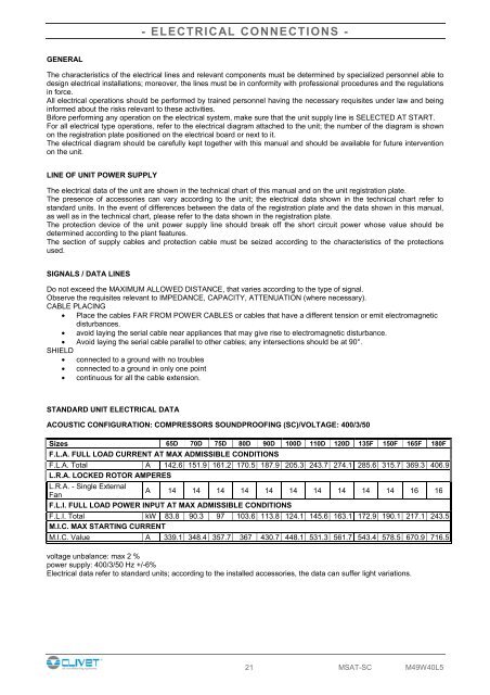
- ELECTRICAL CONNECTIONS -GENERAL- ELECTRICAL CONNECTIONS -The characteristics of the electrical lines and relevant components must be determined by specialized personnel able todesign electrical installations; moreover, the lines must be in conformity with professional procedures and the regulationsin force.All electrical operations should be performed by trained personnel having the necessary requisites under law and beinginformed about the risks relevant to these activities.Bifore performing any operation on the electrical system, make sure that the unit supply line is SELECTED AT START.For all electrical type operations, refer to the electrical diagram attached to the unit; the number of the diagram is shownon the registration plate positioned on the electrical board or next to it.The electrical diagram should be carefully kept together with this manual and should be available for future interventionon the unit.LINE OF UNIT POWER SUPPLYThe electrical data of the unit are shown in the technical chart of this manual and on the unit registration plate.The presence of accessories can vary according to the unit; the electrical data shown in the technical chart refer tostandard units. In the event of differences between the data of the registration plate and the data shown in this manual,as well as in the technical chart, please refer to the data shown in the registration plate.The protection device of the unit power supply line should break off the short circuit power whose value should bedetermined according to the plant features.The section of supply cables and protection cable must be seized according to the characteristics of the protectionsused.SIGNALS / DATA LINESDo not exceed the MAXIMUM ALLOWED DISTANCE, that varies according to the type of signal.Observe the requisites relevant to IMPEDANCE, CAPACITY, ATTENUATION (where necessary).CABLE PLACING• Place the cables FAR FROM POWER CABLES or cables that have a different tension or emit electromagneticdisturbances.• avoid laying the serial cable near appliances that may give rise to electromagnetic disturbance.• Avoid laying the serial cable parallel to other cables; any intersections should be at 90°.SHIELD• connected to a ground with no troubles• connected to a ground in only one point• continuous for all the cable extension.STANDARD UNIT ELECTRICAL DATAACOUSTIC CONFIGURATION: COMPRESSORS SOUNDPROOFING (<strong>SC</strong>)/VOLTAGE: 400/3/50Sizes 65D 70D 75D 80D 90D 100D 110D 120D 135F 150F 165F 180FF.L.A. FULL LOAD CURRENT AT MAX ADMISSIBLE CONDITIONSF.L.A. Total A 142.6 151.9 161.2 170.5 187.9 205.3 243.7 274.1 285.6 315.7 369.3 406.9L.R.A. LOCKED ROTOR AMPERESL.R.A. - Single ExternalA 14 14 14 14 14 14 14 14 14 14 16 16FanF.L.I. FULL LOAD POWER INPUT AT MAX ADMISSIBLE CONDITIONSF.L.I. Total kW 83.8 90.3 97 103.6 113.8 124.1 145.6 163.1 172.9 190.1 217.1 243.5M.I.C. MAX STARTING CURRENTM.I.C. Value A 339.1 348.4 357.7 367 430.7 448.1 531.3 561.7 543.4 578.5 670.9 716.5voltage unbalance: max 2 %power supply: 400/3/50 Hz +/-6%Electrical data refer to standard units; according to the installed accessories, the data can suffer light variations.21 <strong>MSAT</strong>-<strong>SC</strong> M49W40L5