CF-V 31-41-51-71-91-101- 121-142-182-202-242 - Delta-Temp
CF-V 31-41-51-71-91-101- 121-142-182-202-242 - Delta-Temp
CF-V 31-41-51-71-91-101- 121-142-182-202-242 - Delta-Temp

You also want an ePaper? Increase the reach of your titles
YUMPU automatically turns print PDFs into web optimized ePapers that Google loves.
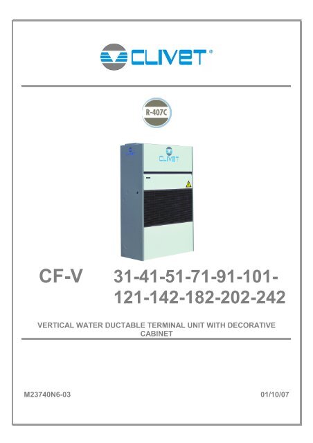
<strong>CF</strong>-V <strong>31</strong>-<strong>41</strong>-<strong>51</strong>-<strong>71</strong>-<strong>91</strong>-<strong>101</strong>-<strong>121</strong>-<strong>142</strong>-<strong>182</strong>-<strong>202</strong>-<strong>242</strong>VERTICAL WATER DUCTABLE TERMINAL UNIT WITH DECORATIVECABINETM23740N6-03 01/10/07
UNIT IDENTIFICATION..............................................................................4INSTRUCTIONS FOR THE USER ..................................................................4GENERAL WARNINGS ...............................................................................5RESIDUAL RISKS ....................................................................................6RECEPTION ...........................................................................................8INSPECTION UPON RECEPTION ................................................................................................................................ 8STORAGE...................................................................................................................................................................... 8HANDLING..................................................................................................................................................................... 8POSITIONING .........................................................................................9GENERAL ...................................................................................................................................................................... 9FUNCTIONAL CLEARANCES ....................................................................................................................................... 9POSITIONING................................................................................................................................................................ 9WATER CONNECTIONS ........................................................................... 10GENERAL .................................................................................................................................................................... 10CONDENSATE DISCHARGE CONNECTION ............................................................................................................. 10WATER HEATING COIL .............................................................................................................................................. 11AIR CONNECTIONS................................................................................ 12FEATURES FOR DUCTS FOR TREATED AIR ........................................................................................................... 12ELECTRICAL CONNECTION...................................................................... 13GENERAL .................................................................................................................................................................... 13STANDARD UNIT ELECTRICAL DATA....................................................................................................................... 13CONNECTION TO THE MAINS................................................................................................................................... 13START-UP ........................................................................................... 17PRELIMINARY CHECKS ............................................................................................................................................. 17AERAULIC SYSTEM.................................................................................................................................................... 17WATER SYSTEM......................................................................................................................................................... 17ELECTRICAL SYSTEM ............................................................................................................................................... 17VERIFy tensions – absorptions .................................................................................................................................... 17REMOTE INPUT CONFIGURATIONS......................................................................................................................... 17SETTING THE SET-POINT ......................................................................................................................................... 17AIR FLOW CHECK ...................................................................................................................................................... 18CONTROL ............................................................................................ 19ROUTINE MAINTENANCE......................................................................... 29MAINTENANCE INSPECTIONS.................................................................................................................................. <strong>31</strong>97/23 CE PED directive................................................................................................................................................ <strong>31</strong>PUT AT REST.............................................................................................................................................................. <strong>31</strong>TROUBLESHOOTING .............................................................................. 32DECOMMISSIONING OF THE UNIT ............................................................. 33DISCONNECTING THE UNIT...................................................................................................................................... 33DISMANTLING AND DISPOSAL ................................................................................................................................. 33TECHNICAL DATA ................................................................................. 34DIMENSIONS ........................................................................................ 36
UNIT IDENTIFICATIONSERIAL NUMBER LABELThe units are identified by the serial number label shown here.The label lists the type of unit (series and size), serial number, yearof manufacture, number of electrical diagram, main technical data,logo and address of the manufacturer.The label is placed on the unit, generally near the electrical paneland also on the external panelling.IT MUST NEVER BE REMOVED.SERIAL NUMBERThis provides unique identification of the machine. It makes itpossible to trace the specific features of the unit and to identify thecomponents installed in it.Without this number, it is not possible to identify with certainty thespare parts that are specific to that unit.When requesting assistance, always provide the type of machineand the serial number.Write them in the space below so that they are readily availablewhen needed.Type of unit : _________________________________Serial number : _________________________________Wiring diagram : __________________________Year of manufacture : ___________________________INSTRUCTIONS FOR THE USER• This is a partial syntex of the information provided in the manual; carefully read this manual• Carefully read this manual. Keep it with the electrical diagram. Make it available to technicians for servicing.• Ask the installer for training on start-up, shutdown, changing set points, placing in at-rest status, maintenance, what to door not to do in the event of a breakdown.• Provide for scheduled maintenance by specialized technicians so as to ensure long-lasting operation of the unit.• If you expect the machine to be shut down for long periods of time, disconnect the electrical power supply. In winter, takenecessary measures to deal with possible freezing (unit and system pipes) .M23740N6-03 01/10/07 page 4
MANUAL PURPOSEThis manual has been designed to enable the unit to beinstalled, started up and maintained correctly.MANUAL INSTRUCTIONSIt is essential to observe these instructions.The manufacturer declines all liability for any damage thatmay be caused whether directly or indirectly to persons orthings if these instructions are not heeded.MANUAL STORAGEThis manual and the unit’s wiring diagram should becarefully stored so that they are readily available to theoperator when required.EXPERT PERSONALThe unit must be installed, tested and maintained by expertpersonal who meet the relevant legal requirements (Italianlaw No. 46 of 5/3/1990).LOCAL SAFET REGULATION INSTALLATIONThe installation must be performed observing the localsafety regulations.POWER SUPPLYMake sure the power supply conforms to the data on theunit’s rating plate, located inside the door of the mainelectrical panel.PACKAGINGThe packaging material (plastic bags, polystyrene foam,nails, etc.) is potentially dangerous and should therefore bekept away from children and recycled in compliance withthe local regulations in force.MAINTENANCEBefore performing any service operations, cut off the power.Perform the operations in conformity with the localregulations in force.PERIODICAL INSPECTIONSPerform periodical inspections to locate possible loosenedor broken parts. If the repairs are not performed, there willbe a higher risk for things and peoples to become damagedand injured.FAULT – POOR OPERATIONSwitch off the unit in the event of faults or poor operation.REPAIROnly have repairs carried out by a service centre authorisedby the manufacturer, and insist on the use of original spareparts only.Failure to comply with the above may compromise thesafety of the unit.MODIFICATIONSThe manufacturer will not accept any responsibility, and thewarranty will lapse, in the event of electric and/ormechanical modifications. Any modification which is notformally authorized, and which does not respect theinstructions given in this manual, will cause the warranty tolapse.INTENDED USEThe unit must only be used for the specific purpose it wasdesigned :GENERAL WARNINGSThe unit is designed for civil air-conditioning within thelimits defined in the technical bulletin and this manual.Any use other than that specified does not imply anycommitment or constraint by the manufacturer in any waywhatsoever.ADDITIONAL SAFETY PRECAUTIONSThis unit has been especially designed and manufacturedso to prevent any risk to persons and health hazard.For this reason, design solutions fit to eliminate (wherepossible) any cause of risk and sensibly reduce theprobability of danger have been adopted.Please refer to the "Residual Risks" section of this manualand strictly observe the behaviour prescriptions listed therein order to prevent any possible risk that hasn’t beenpossible to avoid in the design stage.DATA UPDATINGThe manufacturer may be able to modify the data withoutprior notice as a consequence of constant improvements.REGULATIONS ANDCERTIFICATIONSUNI EN ISO 9001 CERTIFICATIONClivet S.p.A., in order to guarantee customer satisfaction,has chosen the ISO 9001 Quality System as the referencefor all its business activities. This is demonstrated by thecompany’s commitment to ongoing improvements in thequality and reliability of its products; its sales, design,purchasing, production and after-sales service activities arethe means used to reach such purpose.CE MARKClivet products bear the CE mark, in compliance with therequirements of the following EC directives, including thelatest amendments, and with the corresponding nationalapproximated legislation:• - 98/37/CE• - 89/336/CEE as modified by the directives 92/<strong>31</strong>/CEEand 93/68/CEE• - 73/23/CEE as modified by the directive 93/68/CEE• - 97/23/CEM23740N6-03 01/10/07 page 5
RESIDUAL RISKSGENERALThis section lists some of the more common situationswhich, being beyond the control of the manufacturer, couldbe a source of risk to persons or property.DANGER AREAThe figure below highlights the area in which onlyauthorised personnel may operate.• External danger zone, identified by a precise areaaround the unit and its vertical projection on theground in the case of hanging unit.• Internal danger zone, identified by the area that canbe entered only after having intentionally removed theprotecting panels or parts of these.DA = 1000 mmC = 1000 mmACBB = 1000 mmD = 1000 mmHANDLINGIf handling operations are undertaken without adopting allthe necessary safety procedures and exercising due care,the unit can fall or topple, causing damage — possiblyextremely serious — to persons and/or property, and to theunit itself.Ensure the unit is handled and manoeuvred as directed onthe packing and in the present manual, and in accordancewith local regulations.In the event of refrigerant gas escaping, refer to the “Safetydatasheet” for the particular refrigerant.INSTALLATIONIncorrect installation of the unit can result in water leaks,accumulation of condensate, escape of refrigerant, electricshocks, fire, as well as irregular operation or damage to theunit itself.Make certain that the installation is carried out only by aqualified technician, also that the directions contained inthis manual are followed and local statutory regulationsobserved.In the event of the unit being installed in a site where thereis even the slightest risk of inflammable gas escapes andconsequently the possibility of such gases accumulating inarea around the unit, the risk of explosion and fire cannotbe discounted.Take every care and precaution when selecting theinstallation site.Installation on a structure not able to bear the weight and/orafford a secure anchorage of the equipment may cause theunit to fall and/or topple, resulting in damage to persons orproperty, or to the unit itself. Make certain that every careand precaution is taken when positioning and securing theunit.If the unit is easily accessible to children, unauthorizedpersons or animals, this is a situation that can give riseaccidents and injuries, perhaps serious. Install the unit in aplace where access is allowed only to authorized persons,or install barriers or guards preventing unauthorized entry.GENERAL RISKSA smell of burning, smoke or other indications of seriousirregularity could signal the onset of situations liable tocause damage to persons or property or to the unit itself.Isolate the unit from the electrical power supply (red-andyellow)switch.Contact an authorized service centre so that the source ofthe problem can be identified and remedied.Accidental contact with heat exchange coils, compressors,pressure pipelines or other components can result inwounding or burns, or both.Always wear suitable clothing, including protective gloves,when working in the danger area.Maintenance or repairs carried out by unskilled operativescan result in harm or damage to persons and property, or tothe unit itself. Always contact an authorized service centre.Failure to close the panels of the unit, or to check that allthe fixing screws of the panels are properly tightened, canresult in harm or damage to persons or property, or to theunit itself.Verify periodically that all panels are closed and madeproperly secure.In the event of fire, the temperature of the refrigerant canrise to the point that pressure will exceed safety levels andperhaps cause fluid to be projected. It may also happenthat parts of the circuit isolated by closed valves willexplode.Do not stand near safety valves, and never leave the valvesof the refrigerant circuit closed.ELECTRICAL SYSTEMIf the power line connecting the unit to the a.c. supply isincomplete, or if the connection is made with cables ofincorrect cross section and/or with insufficiently ratedprotective devices, this can result in electric shock, toxicityhazard, damage to the unit or fire.All work on the electrical system should be carried outreferring to the wiring diagram and to the directions given inthis manual, and the system itself must be dedicated.Failure to secure the cover enclosing electrical componentscan lead to the infiltration of dust and water, ultimatelycausing electric shocks, damage to the unit, or fire.Always fasten the cover securely to the unit.If live metal parts of the unit are not connected properly tothe earth system, they can cause electric shock or evendeath by electrocution.Make absolutely certain that the connection to the earthsystem is made in accordance with correct practice.Contact with live parts rendered accessible internally of theunit when the guards are removed can result in electricshock, burns or death by electrocution.Before exposing these parts, make certain the isolatingswitch on the power line to the unit is set to the OFFposition and padlocked, and post a warning sign.M23740N6-03 01/10/07 page 6
Contact with parts that could become live when the unit isstarted up can result in electric shock, burns or death byelectrocution.When there is no need for circuits to be powered up, set theisolating switch on the power line to the OFF position,padlock it and post a warning sign.MOVING PARTSContact with the fan rotors can cause injury.Before removing the protective grilles or the fansthemselves, make certain the isolating switch on the powerline to the unit is set to the OFF position and padlocked,and post a warning sign.Before removing the protective grilles or the fansthemselves, make certain the isolating switch on the powerline to the unit is set to the OFF position and padlocked,and post a warning sign.WATER SYSTEMDefects affecting pipelines, connections or valves and othercontrol componentry can result in water being leaked orsprayed from the system, occasioning damage to propertyor causing short circuits in the unit.Make certain all hydraulic connections are securely made,following the directions given in the present manual.M23740N6-03 01/10/07 page 7
INSPECTION UPON RECEPTIONCheck on arrival that the unit has not suffered damageduring transit and that it is complete in every part asspecified in the order. In the event of visibledamage/deficiencies being discovered, make a noteimmediately on the delivery document with the comment:CONDITIONAL ACCEPTANCE — CLEAR EVIDENCE OFDEFICIENCIES/DAMAGE DURING TRANSITInform both the supplier and the carrier of the details by faxand by registered mail with advice of receipt not later than 8days after taking consignment. Notifications sent after 8days have elapsed will be ignored.STORAGEShelter from: direct sunlight, rain, sand and wind<strong>Temp</strong>erature: maximum 60°C minimum -10°CMaximum humidity: 90%The respect of the instructions on the exterior side of thepackaging assures the physical and functional integrity ofthe unit for the final user’s advantage.It is recommended to:• Handle carefully• Keep in a dry place• Avoid putting other objects on top of the unit (respectthe limits of levels of superimposition shown in thepackage)• Avoid placing the unit with thermoretractable protectionunder the sun since the pressure of the circuits canassume values which activate the safety valves.RECEPTIONHANDLINGThe operation of handling the unit must be carried outrespecting the instructions of the safety norms in force(Legislative Decree 626/94 and following modifications)Before starting the handling operations:• Value the critical points during handling (stairs, flights,disconnected routes, doors, etc)• Verify that the lifting capacity of the means used isadequate to the unit weight• Consider that the barycentre could be moved withrespect to the center of the unit• Before starting to lift, verify that the unit is at a stablebalanceThe following examples are indications; the choice of themeans and of the handling modes will depend on factors,such as:• The unit weight• Type and overall dimensions of the unit• Place and route for the handling (dirt yard, asphaltedsquare, etc)• Condition of the place of destination (roof, square, etc)• Handling distance characteristics (distances, flights,steps, doors)LABELS / YELLOW BRACKETS SHOW THE LIFTING POINTSRigid structure to prevent damage to thestructurePosition U-shaped clips on baseAnchor belt to clipsClose with threaded pin.Ensure that the unit is stable and balanced.Keep in mind that the centre of balance may notbe at the centre of the unit.Ensure that the unit is stable and balanced.Keep in mind that the centre of balance may notbe at the centre of the unit.REMOVING THE PACKINGFor removing the packaging, use specific personalprotection for the operator (gloves, glasses, etc.).While removing the packaging, pay attention not to damagethe unit.Check for any visible damage.Dispose of the packaging by taking it to specialist collectionor recycling centres in accordance with local regulations.M23740N6-03 01/10/07 page 8
GENERALFor installing air-conditioning systems, it is necessary toconsider the following:• the technical spaces necessary for the machine andsystem• the place where the machine will be installed• the transport of thermal carrier fluids and relevantconnections to the unit:o watero airo refrigerant (unit in more sections)• electrical connectionsIf these aspects are not evaluated carefully, they canaffect the performances and the working life of the unit.FUNCTIONAL CLEARANCESWhen placing the unit, please respect the functionalclearances indicated in DIMENSIONS section.The functional spaces need to be observed because of thefollowing:• to guarantee the good operation of the unit• to allow the performance of all maintenanceoperationsRETURN AIR RETURN CONFIGURATIONSF10004001000P400POSITIONING1000• to protect the authorized operators and exposedpeopleIf more units are placed close to one another, thefunctional spaces must be doubled.POSITIONING1. The units are designed for INDOOR installations,performed in fixed positions and in areas accessibleonly to qualified and authorized personnel2. SAFETY VALVE (only if present on the unit) : theinstaller is responsible for evaluating the opportunityof installing drain tubes, in conformity with the localregulations in force ( EN 378 )3. Install the unit raised from the ground4. avoid installations in places subject to flooding5. Verify that the fixing/supporting points are level andsuitable to support the weight of the unit (see theweight and the weights distribution)6. to avoid noise and vibrations place a layer of rubberbetween the base of the unit and the floor/support400BPossible return air configurationsF =P =B =Return air returnDischarge airFresh air ductWARNING: When positioning the unit, leave enough space above to allow for theinspection of the air filters and all other components requiring servicecontrols. Leave adequate clearance on the side for the connections and possible checks.Front return ( STD )with grilleBack return with blind panelreplacing the grilleBottom return with blind panelreplacing the grilleCONNECTION PROVISIONSThe fittings are located inside the cabinet in such a way that the connections on-site can be made from the sides or the rear.Pre-perforation featured at the positions indicated in the figure to the side for the piping inlets.COLD WATER COIL CONNECTIONSHOT WATER COIL CONNECTIONSELECTRICAL CONNECTIONSCONDENSATE DRAINM23740N6-03 01/10/07 page 9
WATER CONNECTIONSGENERALPiping must be designed with the least possible number ofbends and head variations. If the pressure chute of theinstallation is above the useful prevalence of the pump, thewater delivery capacity is reduced as well as, as aconsequence, the thermal exchange and the yield.INTERCEPTING VALVESInstall on the input and output of the user parts(exchangers, coils, humidifiers, etc) So that it will bepossible to carry out all the service operations and possiblesubstitutions without emptying the installation.PRESSURE AND TEMPERATURE INDICATORInstall on the input and output of the user parts(exchangers, coils, humidifiers, etc) So that it will bepossible to carry out all the service operations.AUTOMATIC OR MANUAL ESCAPE VALVESInstall the highest points of tubes in a way that the air canescape form the circuit.BLEEDING COCKInstall them at the lowest points of the circuit, so as to allowemptying.LEAKAGE TESTSBefore performing the insulation of the tubes, carry out aleakage test.TUBE INSULATIONAll tubes of water must be insulated so that to avoid theformation of condensation and thermal dispersions alongthe tubes themselves. Verify that the insulation is thevapour coil type. The connections for the air escape and forthe emptying must be out of the insulating thickness toassure the accessibility.CONNECTIONS SUPPORTSThe weight of the hydraulic connections must be supportedin the exterior of the unit so as not to stress the connectionsof user devices (exchangers, coils, humidifiers, etc ) .ANTI-VIBRATION DEVICESIn case of units with anti-vibration devices, it is necessary toassemble elastic joints, even on water connections.RISK OF FREEZEIf the unit and the relevant water connections are subject totemperatures near 0°C:• mix the water of the system with glycol• protect the tubes with heating cables under the tubesinsulation• empty the system by verifying that:ono taps are closed so they can not trap the water,even after emptyingo there are no low points where the water canstagnate even after emptying; blow if necessaryINSTALLATION EMPTYINGThe refilling of the water present in the installation increasethe oxidation phenomena and lime deposits.If necessary empty only the interested system section andanyway empty or refill the installation if necessary .EXPANSION TANKThe installation must be kept at the right pressure by bothan expansion tank and a combined valve of pressurereduction and discharge; if the components are present onthe unit, they must be installed on the installation. Theexpansion tank must be dimensioned in function of thewater in the installation.MAX. WORKING PRESSURE =10BarARIES EFFECTS AND AIR BUBBLES CAN PRODUCETHE OVERCOMING AND CAUSE WATER DROPS.CONDENSATE DISCHARGE CONNECTION.1. The condensate must be dispersed to avoid damages topersons and property.2. Unit discharge fitting : the connection must avoid thetransmission of mechanical stresses and must beperformed paying attention to avoid the damaging of theunit discharge fitting3. Make a trap that, eliminating the depression caused bythe fan, stops the return of gas from the discharge pipe(see the figure).4. Connect the condensate discharge to a rainwater drain.Do NOT use sewerage drains, so as to avoid the returnof odours if the water contained in the trap evaporates.5. Finally, check that the condensate will drain correctly bypouring water into the tray stud.6. RISK OF FREEZE : If the unit operates in cooling withoutside temperatures lower than 0°C, value thepossibility that the condensate can freeze blocking thedownflow and provoking flooding. Use heat cables orother devices to guarantee the disposal.M23740N6-03 01/10/07 page 10
WATER HEATING COILOPTIONAL - The position of the connections is shown onthe dimensional drawing of the unit.The air valve is placed on the top of the coil manifold, it isused to eliminate possible air bubbles on the circuit.The discharge valve is placed on the bottom of themanifold, it is used to empty the coil if it is unused for along period.TO AVOID THE FREEZE FORMING INSIDE THE COIL1. If the unit or the relevant water connection aresubjects to temperatures next to 0°C see RISK OFFREEZE in the GENERAL WARNINGS paragraph.2. The freeze forming is possible also in summer inabnormal operating conditions (ex. Insufficient airflow-rate for clogged filters). It is so recommended toglycolate or empty also in summerKey:1 – Air bleed valve2 – Water input3 – Water supply4 – Discharge valveWATER CONNECTIONSSizes∅ GAS<strong>31</strong>-<strong>41</strong>-<strong>51</strong>-<strong>71</strong> 1”<strong>91</strong>-<strong>101</strong>-<strong>121</strong> 1” ¼<strong>142</strong>-<strong>182</strong> 1” ½<strong>202</strong>-<strong>242</strong> 2”M23740N6-03 01/10/07 page 11
Proper execution and sizing of air connections are essentialfor ensuring correct operation of the unit and an acceptablelevel of silence in the room.When designing and creating ducts, consider PRESSUREDROPS, FLOW RATE and AIR SPEED which need to becompatible with the characteristics of the unit. Specialconsideration needs to be made for pressure drops that aregreater than the unit's static pressure, which would lead toa reduction in flow rate resulting in unit shutdown.the weight of the ducts must not be supported by theconnection flangesAIR CONNECTIONSplace anti-vibration joints between the ducts and theunitthe connection to the flanges and between the varioussections of the ducts must ensure an airtight seal,preventing leakage in delivery and return which wouldcompromise overall system efficiency.limit pressure drops by optimizing the path, the typeand number of curves and the branchesuse curves with a wide radius. Consider whether itmight be useful to equip them with deflectors(especially if the air speed is high or if curves are tight)FEATURES FOR DUCTS FOR TREATED AIR1. The inner surface of the duct must be smooth andwashable. It must not contaminate the air.2. Thermally insulate the ducts and the flanges so as toprevent loss of energy and condensation build-up.Proper distribution of air in the room is essential forensuring comfort levels.In the selection and positioning of grilles, outlets anddiffusers, the following are to be avoided:3. excessive air speed4. formation of stagnant zones and layering5. entry of cold air into the room6. formation of localized currents (due to uneven airdistribution)7. excessive variations in ambient temperature in thevertical and horizontal planes8. short circuiting of delivery air towards return airFor purposes of comfort, the following things need to beconsidered:9. air diffusers must be selected by checking the soundpower generated at nominal flow rate conditions10. the disconnections to the diffusers are to be madeusing flexible elements11. the return grilles must be amply sizedM23740N6-03 01/10/07 page 12
ELECTRICAL CONNECTIONGENERALThe characteristics of the electrical lines and relevantcomponents must be determined by SPECIALIZEDPERSONNEL ABLE TO DESIGN ELECTRICALINSTALLATIONS; moreover, the lines must be inconformity with professional procedures and the regulationsin force.All electrical operations should be performed by trainedPERSONNEL HAVING THE NECESSARY REQUISITESUNDER LAW and being informed about the risks relevantto these activities.Before performing any operation on the electrical system,make sure that the unit supply line is SELECTED ATSTART.The earth connection must be made prior to other electricalconnections.For all electrical type operations, REFER TO THEELECTRICAL DIAGRAM ATTACHED TO THE UNIT; thenumber of the diagram is shown on the registration platepositioned on the electrical board or next to it.The electrical diagram should be carefully kept togetherwith this manual and should be AVAILABLE FOR FUTUREINTERVENTION ON THE UNIT.LINE OF UNIT POWER SUPPLYThe ELECTRICAL DATA OF THE UNIT are shown in thetechnical chart of this manual and on the unit registrationplate. The presence of accessories can vary according toSTANDARD UNIT ELECTRICAL DATAthe unit; the electrical data shown in the technical chartrefer to standard units. In the event of differences betweenthe data of the registration plate and the data shown in thismanual, as well as in the technical chart, please refer to theDATA SHOWN IN THE REGISTRATION PLATE.The protection device of the unit power supply line shouldbreak off the short circuit power whose value should bedetermined according to the plant features.The section of supply cables and protection cable must beseized according to the characteristics of the protectionsused.SIGNALS / DATA LINESDo not overpass the maximum power allowed, whichvaries, according to the type of signal.Lay the cables far from power cables or cables having adifferent tension and that are able to emit electromagneticdisturbances.Do not lay the cable near devices which can generateelectromagnetic interferences.Do not lay the cables parallel to other cables; cablecrossings are possible, only if laid at 90°.Connect the screen to the ground, only if there are nodisturbancesAssure the continuity of the screen during the entireextension of the cable.Observe, if any, the requirements about impendency,capacity, attenuationVOLTAGE 230/1/50Sizes <strong>31</strong> <strong>41</strong> <strong>51</strong> <strong>71</strong>F.L.A. FULL LOAD CURRENT AT MAX ADMISSIBLE CONDITIONSF.L.A. - Total A 2,1 3,6 4,5 5,7F.L.I. FULL LOAD POWER INPUT AT MAX ADMISSIBLE CONDITIONF.L.I. - Total kW 0,25 0,25 0,52 0,6Voltage unbalance: max ± 2% with an admitted tolerance: ± 6%VOLTAGE 400/3/50Sizes <strong>91</strong> <strong>101</strong> <strong>121</strong> <strong>142</strong> <strong>182</strong> <strong>202</strong> <strong>242</strong>F.L.A. FULL LOAD CURRENT AT MAX ADMISSIBLE CONDITIONSF.L.A. - Total A 2,2 3,1 4 4 5,5 5,5 7,5F.L.I. FULL LOAD POWER INPUT AT MAX ADMISSIBLE CONDITIONF.L.I. - Total kW 0,75 1,1 1,5 1,5 2,2 2,2 3Voltage unbalance: max ± 2% with an admitted tolerance: ± 6%CONNECTION TO THE MAINS1. Make sure that the sectioning device at the beginning ofthe unit’s power line is opened, locked and equippedwith a signal.2. Open the general line disconnecting switch (if present)3. Verify that the net is in conformity with the data shownin the registration plate placed on the electrical board.4. Check the dimensional drawing for the input of theelectrical lines5. Take away the closing plate placed on the electricboard (ONLY IF PRESENT) and drill a hole through itto pass the cables through)6. Protect the cables, using the fairlead of an adequatesize.7. Using the layout of the electrical diagram, single out theconnecting terminals of the electrical supply cables, ofthe neutral (if foreseen) and the PE protection cable8. Connect the cables to the relevant terminal boards9. Before supplying power to the unit, make sure that allthe safety devices that were removed during electricalconnections are positioned again.M23740N6-03 01/10/07 page 13
FUNCTIONAL CONNECTIONSUNIT WITH 3-SPEED BOARD (only sizes <strong>31</strong>-<strong>41</strong>-<strong>51</strong>-<strong>71</strong>)FOR ALL THE CONNECTIONS MAKE REFERENCE TO THE ELECTRICALPANEL SUPPLIED WITH UNITTR1The module allows to control the fan speed.The speed, according to the user interface, can be:• 3 speed with appropriate selector (not supplied)• modulating control of the speed from min. to max. by potentiometer (not supplied)SELECTORo low speed control input to term. 3 Lo medium speed control input to term. 3 Mo high speed control input to term. 3 HPOTENTIOMETER 2200 ohmo Fan control of the continuous controlo Potentiometer supply to terminal (positive pole)o Potentiometer supply to terminal 5 (negative pole)Terminals T T: remote ON – OFFTR1: ADJUSTMENT TRIMMER OF FAN SPEEDThe factory calibration of the fan speed is equal to 220V AC.Depending on the pressure drops of the ducts the air flow rate of the unit may have to be reduced at maximum speed. Byacting on trimmer TR1 anticlockwise the control power of the motor and consequently the flow rate of the unit are reduced (1/4turn is equal to approximately -40 AC). By acting on the trimmer clockwise the flow rate at minimum speed can be increased.Check that the air flow rate is the unit nominal one (see general technical data).ATTENTION: by changing one of the 3 possible speed modes of the motor the other two are automatically altered. Wetherefore recommend checking that voltage and minimum speed do not fall below 110V AC. The air flow rate at minimumspeed must not be less than the one shown in the table.These operations must be performed when the unit has been permanently installed (with all the system accessories, filter,grilles, ducts, etc.) and with the aid of instruments suitable for the measurement of flow rate and voltage (anemometer andmultimeter).Size 21-25 <strong>31</strong> <strong>41</strong> <strong>51</strong> <strong>71</strong>800 m 3 /h 1000 m 3 /h 1200 m 3 /h 1400 m 3 /h 2000 m 3 /hFlow rate222 L/sec 277 L/sec 333 L/sec 388 L/sec 555 L/secThe 3 speed board can be coupled to:HID-E1 3 SPEED SELECTORSelection of the 3 speed: MIN – MED – MAXSUMMER / WINTER manual changeM23740N6-03 01/10/07 page 14
FUNCTIONAL CONNECTIONSFOR UNIT WITH TERMINAL SPACE ELECTRONICS(unit with CTS option) HID-T2, HID-T3 or HID-TI2 THERMOSTAT21.0REMOTEE c oECOAUTOC le a nThe TERMINAL SPACE electronics can be coupled to the ambient controls below indicated.In both cases the type of cable used must be 2x0.35 mm 2 with shield on the gnd.Max distance: 15mHID-T2 electronic ambient controlTEMPERATURE probe management (HID-T2)OR TEMPERATURE + HUMIDITY (HID-T3)12 +3 gnd4 -<strong>51</strong>2 11 10+ -- gndBuilt-in electronic ambientcontrol HID-TI2<strong>121</strong>110987+-NETUNITTHERMOSTATThe recessed room control is supplied with a series of supports that make it possible to adapt it to the main civil seriesof plates: refer to the instructions provided with the thermostat.POSITIONING OF THE ROOM THERMOSTATThe selection of the place of installation is decisive for room comfort and energy consumption.The thermostat must be positioned:• in a room with average temperature and humidity that are representative of other rooms• at a height of 150 cm• preferably on an internal wallPositions to avoid:• near sources of heat (lamps, computers, etc.)• exposed to direct sunlight• in a position in the direct flow of air from outlets of diffusers• behind curtains of pieces of furniture• near doors and windows to the outside• on walls where there are chimneys or heating pipes• on external wallsM23740N6-03 01/10/07 page 15
ELECTRICAL CONNECTIONS TO BE HANDLED BY THE CLIENTFor all connections refer to the electrical diagram supplied with the unit.• REMOTE ON – OFF• Modulating valve H2O (power supply 24V to be provided for by the client).It is possible to control one valve only (2-pipe-systems) or two different valves for heating and cooling (4-pipesystems)• Fresh air Shutter• Room thermostat• RS485 serial line (refer to document RS 485 NETWORK GUIDELINES)• Electrical resistance sectionIf present, the electrical resistances must be enabled by modifying the following parameters:P24 = 3 enables INPUT 2 as resistance thermal alarmP27 = 1 main heating elementP53 = 3 signal 0-10VRS485 SERIAL PORTIf Clivet provides only the units with BMS communication port (installed or provided separately), it is responsible only forthe units themselves and not for the units downstream. Therefore CLIVET is not responsible for operations such aschoice and installation of cables, connection, serial addressing and checks on network functionality.On request, Clivet provides the specifications for the communication protocol of its units and the necessary guidelines toconnect them to RS485.The card for RS485 serial line must be connected to the main card using the appropriate wire provided.The network termination jumper alongside the screw terminal board for the connection of 485 must be inserted if the unitis the last one in the network.JUMPER :DISINSERITO - INSERITOFollowing some indications for the serial connection ; refer anyway to the CLIVET “RS 485 NETWORKS.- The total length of each serial line, has not to bemore than 1000 metres- The potential difference between the “earths” oftwo RS485 devices must be lower than 7 V- Twisted and shielded couple of conductors- Conductor section 0.22mm2…0,35mm2- Nominal capacity among the conductors < 50pF/m nominal impedance 120 Ω- Recommended cable BELDEN <strong>31</strong>05 ATYPE OF NETWORKThe serial lines must be connected in bus typology, i.e. nodes to more points are not admitted.OK NO !Supervision Sistema di supervisionesystemSHIELD- It must be connected to a ground with no troubles- Connected to the round in only one point- The shield continuity must be kept constant duringall the serial shield extension.M23740N6-03 01/10/07 page 16
START-UPALL THE EQUIPMENT MUST BE COMMISSIONED BY AUTHORISED SERVICE CENTRES.THIS SERVICE IS LIMITED TO START-UP OF THE UNIT ONLY AND NOT THE CONNECTIONS OR INSTALLATION OFTHE SYSTEM.ONLY QUALIFIED TECHNICIANS MUST PERFORM THE FOLLOWING OPERATIONS.PRELIMINARY CHECKSBefore checking, please verify the following1. the unit should be installed properly and in conformitywith this manual.2. the electrical power supply line should be sectioned atthe beginning.3. the sectioning device is locked and the proper warning“not to operate” sign is placed on the handle.4. make sure no tension is presentAERAULIC SYSTEMCheck that:1. the air filters are not removed from unit and arecleaned (possible ventilation checks and the operatingstarting period determinate a ducting “cleaning” withconseguent filter precocius clogging, filters that mustbe cleaned and replaced)2. ducting are completed, connected and withoutobstructions3. possible dampers are opened (for ex. fire stopdampers) and calibrated (for ex. fresh air damper,control damper, ejection damper)4. Grilles, outlets, and diffusers must be free ofobstructions (furniture, shelves, etc.), open and precalibrated,so as to ensure proper air distribution,which is essential to comfort in the room.WATER SYSTEMEnsure that the plumbing system has been washed. Drainthe wash water before connecting the unit to the system.Check that the water circuit has been filled andpressurised.Perform a seal check at max. working pressure checkingthat no leaks are present.Check that the shut-off valves in the circuit are in the"OPEN" position.Check that there is no air in the circuit. If required, bleed itusing the vent valves in the system.Check that there are no ARIES EFFECTS in the transient(pump and / or valve activation/deactivation)When using antifreeze solutions, make sure the glycolpercentage is suitable for the type of use envisaged.% weight of ethylene10 % 20 % 30 % 40 %glycolFreezing point - 4 °C - 9 °C - 15 °C - 23 °CSafety temperature - 2 °C - 7 °C - 13 °C - 21 °CCheck that the circulating pumps are not blocked. In fact,their motor shaft may seize up, especially after longshutdowns. Unblocking can be accomplished with ascrewdriver using the purge hole.ELECTRICAL SYSTEMCheck the proper tightening of the screws that fix theconductors to the electrical components in the board(during handling and transportation, the vibrations couldhave loosened them).Verify that the unit is connected to the ground plant.Control that all panels and protection devices of the unitare repositioned and blocked.Charge the unit by closing the sectioning device, but leaveit on OFF.Make sure that the tension and net frequency values arewithin the limit of:230 +/- 6% single phase unit; 400/3/50 +/- 6% three-phaseunitControl the unbalancing of the phases: it must be lower than 2%.Example:L1 - L2 = 388 V, L2 - L3 = 379 V, L3 - L1 = 377 Vaverage of the measured values = (388 + 379 + 377) / 3 =381maximum deviation from the average = 388-381= 7VUnbalancing = (7/381) x 100 = 1.83% = ACCEPTABLEOperating out of the indicated limits causes the loss of theguarantee as well as very serious damages.VERIFY TENSIONS – ABSORPTIONSCheck that the temperatures of the fluids are included inthe WORKING LIMITS.If the controls of the previous paragraphs are positive, it ispossible to restart the unit.For information on the control panel, refer to the paragraphCONTROL.While the unit is working (ATTENTION ELECTRIC RISK:WORK SAFETLY) check:• Power supply tension• Phase unbalance• Total absorption of the unit• Absorption of the single electric loadsREMOTE INPUT CONFIGURATIONSCheck used remote inputs are activated (ON-OFF etc.) asgiven in the instructions in the ELECTRIC WIRINGchapter.SETTING THE SET-POINTCheck if it is necessary to modify the set-points shown inthe CONTROL chapterM23740N6-03 01/10/07 page 17
AIR FLOW CHECKThe effective unit flow-rate is function of the aeraulicsystem characteristics.It is so necessary to check the air flow-rate and eventuallyto proceed with the appropriate calibrations on the system(dampers, diffusers etc) and on the unit (fan speed control,pulley calibrations etc in base of the unit type and itsconfiguration). Before performing the check, make sure thatthe system has been completed in all its parts (derivations,dampers, grilles, diffusers etc) .PaD2B1ACA = system calculated curve1 = project theorical working point3 = if the system has pressure drop lower than the projectones, the working point will be the 3,with flow-ratehigher that the project one2 = if the system has pressure drop higher than the projectones, the working point will be the 2, with flow-ratelower that the project oneIn the time the working point can change, for example forthe operations on the system (grilles covered by furniture,closed outlets to modify the air diffusion, exclusion oraddition of the distribution sections etc.) or for lackingmaintenance (clogged air filters, blocked dampers etc) .3D = unit head-flow rate curveL/secM23740N6-03 01/10/07 page 18
ECOAUTOCONTROLCONTROL(FOR UNIT WITH CTS TERMINAL SPACE ELECTRONICS AND HID-T2 ,HID-T3 , HID-TI2 THERMOSTAT)21.0REMOTEEcoSwingLOCAL OR REMOTE MANAGEMENTThe unit can be managed locally from the thermostat or remotely through the use of a RS485 serial line with MODBUSprotocol.ONThe unit can be switching on/off:• by thermostat• by digital input (set by parameter)• by net (set by parameter)OPERATIONThe unit has 2 set-points: one for heating and one for cooling. The first one is automatically kept lower than the second onewith a difference of at least 1°C.The regulation module compares ambient temperature with the set-point and tries to keep it as close as possible to it;therefore, it varies the fan speed, the water capacity or both of them according to the configuration.The unit operating is enabled only if the water temperature:• in WINTER is higher than 30°C• in SUMMER is lower than 20°COPERATING MODESAUTOMATICMANUALECOMANUAL FANANTI-TAMPERINGLOCKThe modules automatically commute in cooling or heating mode.The change occurs according to the input water temperature (2-pipe unit) or return air (4-pipe unit.Set the P<strong>31</strong> parameter = 1You choose manually if activating cooling mode or heating mode using the relevantkeysSet the P<strong>31</strong> parameter= 0Economic operation, it prefers saving energy more than comfortin cooling mode the setECO is higher than the standard setin heating mode, it is lowerthe deviation value is defined by P10 OffsetEcoFan speed is set manually;however, the unit regulates the environment temperature according to the AUTO, MANUALor ECO modesAny attempt to change settings is prevented: the thermostat keys are deactivated.CHANGE OF AUTOMATIC MODE – 2-PIPE UNITIn this mode, a neutral zone is foreseen when the unit is positioned in a CHANGE OVER status for a time sufficient to probewater temperature.The status is displayed by a “CO” flashing.After that time, if water temperature is out of limit, the H2O alarm is signalled.Water temperature is detected (therefore, the cooling/heating modes are defined) only if power is demanded. In this operationtype, COOLING and HEATING sets are activated simultaneously; when one of the set is bypassed, water temperature isdetected and the mode is defined.When thermo-regulator sets are met, the last operation mode is displayed.The set that is the opposite to the actual one is determined internally by the regulator by a constant that is definedZoneChangeOver:with unit in COOLING: set heating (opposite)= current set – ZonaChangeOverwith unit in HEATING: set cooling (opposite) = current set + ZonaChangeOverM23740N6-03 01/10/07 page 19
AUTOMATIC MODE CHANGECOOLINGONCHANGEOVERHEATINGONOFF<strong>Temp</strong> H2O1 °C1 °CVALVE IN THE AUTOMATIC MODEvalveP02P03ON0,3°CSetsod.0,3°COFFVALVE IN THE AUTOMATIC MODE IN ECO MODEsetHEATsetCOOLT amb . °CvalveOffSetEcoOffSetEcoONOFF0,3°0,3°CsetHEATsetCOOLT amb . °CHID-T2 or HID-T3 ROOM THERMOSTATset-pointvisible if unit managed byNET (if present)visible with active HUMIDIFICATION/DEHUMIDIFICATION(if present)visible in ECO modevisible with unit inCOOLING21.0REMOTEECOAUTOHID-T2visible with unit in HEATINGEcoSwingvisible if the cooling/heatingchoice is AUTOMATICswitch the thermostat onpress and hold the ON OFF key for 4 secondsIf the function is managed remotely via ModBus, no modification is possible (the word REMOTEstarts flashing)Activate / deativate the ANTI-TAMPERING LOCKPress and hold ECO + SWING keys for 5 secondsThe lock is shown by three horizontal bars when any key is pressed.If the function is managed remotely via ModBus, no modification is possible (the word REMOTEstarts flashing)HID-T+5 secSwingM23740N6-03 01/10/07 page 20
Modify the set-pointPressing on the arrows raises or lowers set-point of the actual operation (heating, ECO heat.,cooling ECO cool.).The difference between the two set-points can not be less than 1°C and this value is automaticallymaintained.If, for example, the unit is in cooling mode and the summer set point is decreased up to the winterset value, the winter set value is also decreased.If the function is managed remotely via ModBus, no modification is possible (the word REMOTEstarts flashing)Display the ambient temperaturePress and hold both arrows of the SET key, and the ambient temperature will be displayedalternated to the “ t a ” writing.Display room humidityONLY FOR HID-T3 THERMOSTAT WITH UR PROBEPress and hold both arrows of the SET key, and the ambient temperature will be displayedalternating with the letters “ta”..Press and hold the Set key again to see the humidity value alternating with the letters “ur “.Switch from the HEATING mode to the COOLING mode and vice versaIf the unit is in manual mode, the switch is performed by the relevant key (cooling ; heating )If “AUTO” is displayed, the switch from one mode to another is managed automatically from the unitand, if this key is pressed, no change occurs.If the function is managed remotely via ModBus, no modification is possible (the word REMOTEstarts flashing)Switch the unit to ECO modePress the ECO keyRepeat the operation to restore the standard operationThe ECO summer set point is higher than the SUMMER set point; the ECO winter set point is lowerthan the WINTER set point.If the function is managed remotely via ModBus, no modification is possible (the word REMOTEstarts flashing)Switch the unit to MANUAL VENTILATIONAUTOMATIC ventilation:the fan speed is self-adjusted according to ambient temperatureMANUAL ventilation:speed is increased or decreased by the user.HOLD PRESSEDcoolingheatingPressing one of the two arrow keys, the automatic ventilation is deactivated.In manual ventilation, the bar corresponding to the active speed is flashing.To restore the AUTOMATIC ventilation:Increase to maximum speedAnother pressure of the key will make all 8 bars flashIf no action is performed, the unit returns to automatic ventilationIf the function is managed remotely via ModBus, no modification is possible (the word REMOTEstarts flashing)Open / close the air supply damper (if present)SwingM23740N6-03 01/10/07 page 21
ALARMS VISIBLE BY THE DISPLAYBEFORE RESETTING AN ALARM, IDENTIFY AND ELIMINATE THE CAUSE OF THE STOP; REPEATED RESETS CANCAUSE IRREVERSIBLE DAMAGE.The ALARMS show a potentially dangerous situation for the unit.Before resetting an alarm, identify and eliminate the cause of the stop; a repeated reset can cause irreversible damage.In the event of doubt, ask for an authorized assistance centre.The table refers to all the variables that are managed by the electronic system.According to the unit configuration and its accessories, few alarms might not be significant.RESFESBT1BT2BT3H2OSLFCOEHHSYSERRActive resistance alarmActive electrostatic filter alarmAir probe fault alarmWater probe fault alarmFresh air probe fault alarmWater temperature alarm not fitActive level sensor alarmMode change in progress (for the automatic mode); is not an alarmLack of communication/wrong thermostat connectionFault internal to the control moduleConfiguration errorPARAMETERSACCESS TO PARAMETERSFOR THE STANDARD USE, THE ACCESS TO PARAMETERS IS NOT NECESSARY.THE FOLLOWING OPERATIONS ARE NECESSARY FOR CALIBRATIONS AND CONFIGURATIONS, THEY AREEXPRESSLY ADDRESSED TO THE AUTHORIZED ASSISTANCE CENTRES OR QUALIFIED TECHNICIANS.Switch on and off the thermostat with the ON-OFF key and wait until the displayshows the set-point.Within 5 seconds, press the SWING and ON-OFF keys simultaneously until the P01code appearsSwing+in 5 secuse the “UP” and “DOWN” keys to scroll along the parametersThe value of the parameter to be modified is displayed with the ECO keyDecrease or increase the parameter valueThe new parameter value is memorized with the ECO keySimultaneously press the SWING and ON-OFF keys to exit until the set-point appearsSwing+M23740N6-03 01/10/07 page 22
LIST OF THE PARAMETERS ACCESSIBLE BY THE THERMOSTATPar Description range UM Def.P01 BandaLavoro: Working band 0 ÷ 15.0 °C 2.0P02P03P05P06MaxH2Ocool:Water max. temperature for cooling operatingMinH2OHeat:Water min. temperature for heating operatingTimeOnPeriodicalDefines the duration of the ON phase of the periodicalTimeOffPeriodicalDefines the duration of the OFF phase of the periodical0 ÷ 30.0 °C 20.00 ÷ 40.0 °C 30.00 ÷ 999 min 20 ÷ 999 min 5P10 OffsetEco 0 ÷ 4.0 °C 3.0P11 SetUrHeat: Heat UR set point 30 ÷ 70 % 50P12 BandUrHeat: Intervention band of the heat humidifier 0 ÷ 10 % 5P21P22P<strong>31</strong>FanOffCool:Fan status at “cooling” thermoregulator, satisfied.0: stop, 1: continuous , 2: periodicalFanOffHeat:Fan status at “heating” thermoregulator, satisfied.0: stop, 1: continuous , 2: periodicalModoAuto:It enables the automatic saison change0: Manual, 1: Auto0…2 num 20…2 num 00…1 flag 0P<strong>41</strong> BT1 probe calibration -9.9 +10.0 °C 0.0P42 BT2 probe calibration -9.9 +10.0 °C 0.0P43 Thermostat temp. probe calibration -9.9 +10.0 °C 0.0P44 Thermostat UR probe calibration -9.9 +10.0 %UR 0.0S01 TESToperativa °CS02 TH2Ooperativa °CS03 TARIAoperativa °CS04 URoperativa Hr%S05 Actual mode bitmapS06 CurrentSetpoint °CS07 Current humidity Set Hr%S08 Errors bitmapS09 Active humidifcation flagS10 Active dehumidification flagS11 FanStatus : 0: off, 1: on 0…1 flagS12Actual fan:0-7 if motor 0-10 V0-3 if 3 speed motor0-1 if single-speed motor0…7 numM23740N6-03 01/10/07 page 23
SELECTION OF MODE OF OPERATIONIf you press for about 3 seconds on the key il the display will show the symbols that define current operating mode.if you press the key you can select the desired operating mode in the following cyclical sequenceheating→Economicalheating→ cooling →Economicalcooling→ventilationwhen you press the key [OK] you confirm the displayed mode. The symbols will flash during setting of the mode, and thennormal operation resumes.During programming of the operating mode, if no key is pressed for about 10 seconds, you will go back to normal operation,without modifying the operating mode.MODIFICATION OF ADJUSTMENT SET POINTIn normal operation, for operating modes that include it, you can modify the adjustment set point using the keys [] e []respectively to increase/decrease in steps of 0.1°.MANAGEMENT OF FAN SPEEDVENTILATION MODEin VENTILATION MODE, no adjustments are made to the temperatureyou can change fan speed using keys and .MODES: HEATING, ECONOMICAL HEATING, COOLING, AND ECONOMICAL COOLINGpress briefly on the key : the display will show the message “Fan” andthe bar of the fansuse the keys and select the desired speedgo back to normal operation by pressing the key OKDuring fan speed modification, if no key is pressed for about 10 seconds, normal operation will resume, preserving anymodifications that have been made.When setting fan speed, you will go from AUTOMATIC (where the speed of the fans is controlled automatically based onambient temperature) to MANUAL operation where the user sets the speed.To go back to automatic fan operation, repeatedly press until the entire bar is flashing.MANUAL STATUS OF THE FANS IS INDICATED BY A FLASHING BARThe setting of fan speeds is not cyclical.SILENCED MODETo activate/de-activate silenced mode briefly press the key OK.Silenced mode is indicated on the display by the message SIL.DISPLAY OF AMBIENT TEMPERATUREYou can display the ambient temperature as measured by the probe on the thermostat or the one on the unit. From normaloperating status:press briefly on key : the display will show the message Fan and the bar of the fans.press key again: the display will show only the message tA.press the key [OK] to confirm the selection: The message tA will flash on the display, followed by a return to normal operationin which the message tA will alternate with the ambient temperature for a few seconds.You can also go back to normal operation by pressing, instead of the key OK the key or you can wait about 10 secondswithout pressing any key.SWING MODE - CONTROL OF AIR SUPPLY FLOATING SHUTTERIn normal operating status, you can activate/deactivate the Swing function by simultaneously pressing the keys [] and [].There is no indication on the display for the activation/deactivation of this function.M23740N6-03 01/10/07 page 25
BATTERY CHECKEach time it is powered on, and whenever it is disconnected from the CLIVETBUS, thedevice performs a check of the battery charge, which is the source of auxiliary power.If the battery is nearly dead, the message bAt will appear.bAtThe instrument also works even without an auxiliary power supply. In this case, only the functions related to the front keypadare accessible.SIGNALLING OF ALARMS AND MALFUNCTIONSAny alarms generated by the terminal unit are displayed by the following codes:RESFESBT1BT2BT3H2OSLFCOEHHSYSERREURActive resistance alarmActive electrostatic filter alarmAir probe fault alarmWater probe fault alarmFresh air probe fault alarmWater temperature alarm not fitActive level sensor alarmMode change in progress (for the automatic mode); is not an alarmLack of communication/wrong thermostat connectionFault internal to the control moduleConfiguration errorFault humidity probeThe alarm “EHH” is shown about 30 seconds after communication problems between the device and the adjustment unit.ADVANCED PROGRAMMINGHidden buttons for use by installer: accessible by extracting the thermostat from its housing.5, 6: not usedkeys accessible only with a tool7: reset of the fan fonct. hoursR: thermostat reset A R8: it hides the dirty filtersA: thermostat starting11 10 9 8 7 6 59: self-addressing10: access to the configuration parameters11: keypad lock/unlockKEYPAD LOCKUsed to disable functions related to the pressing of user keys.Take the thermostat out of its housing, and press the key [11]. The display will show themessage bLCput thermostat back in placeThe message bLC will flash until the procedure is complete (a few seconds).From this moment on, pressing any key will not have any effect, and will instead causethe display to momentarily show the message bLC.To go back to a normal situation, release the keypad lock and repeat the operation.bL<strong>CF</strong>or further details on advanced programming see instructions provided with the room thermostat.VENTILATIONThe system can manage 2 types of ventilation, depending on the type of unit: ON / OFF 3 speed modesFor any further clarification regarding the type of ventilation refer to the unit electrical diagram.M23740N6-03 01/10/07 page 26
COOLINGHEATINGtype of ventilationThe ventilation is activated if:T H2O < P02 Maxh2oCoolT H2O > P03 MinH2OheatIf the temperature is out of these limits whenthe delay time is finished, the H2O alarm is If the temperature is out of these limits whenactivatedthe delay time is finished, the H2O alarm isactivatedT H2O < T ambienteONONON / OFFSizes <strong>91</strong>÷<strong>242</strong>OFF T amb. °COFFp01 = BandaLavorop01 = BandaLavoroT amb. °CSet-pointSet-point3 V3 V2 V2 V3 speedSizes <strong>31</strong>÷<strong>71</strong>1 V1 VSet-pointp01 = BandaLavorop01 = BandaLavoroSet-pointWATER VALVEThe system can control 2 ON-OFF valves, one for heat and the other for cold; they are connected to the basic module.The valve is opened when the thermo-regulator asks for power.Type of valve COOLING HEATING%valve%valve0 – 10 v0 %OFFONp01 = BandaLavoroT amb. °C0 %p01 = BandaLavoroONT amb. °COFFSet-pointSet-pointFRESH AIR DAMPERBy using the proper dedicated output, it is possible to activate a damper or a fan to allow new air to enter the room.M23740N6-03 01/10/07 page 27
ELECTRIC RESISTANCESThe electric resistance operating mode is defined by the following parameters:P27 ModeRes = 0 integration element (ventilation forced at max.)1 main element (manual or automatic ventilation)P53 OutResType = 1 single-phase2 two-phase3 0 – 10 voltINTEGRATIONONOFFP01P01Set PointMAIN ELEMENTONOFFP01Set PointThe water valve is opened when thermoregulationis demanded:if the probe detects hot water, the resistorsautomatically become an integration body.On the contrary, if after TimeValve is over,water temperature is not suitable, the valvecloses, the H2O alarm is not activated and theresistors are not activated.As soon as the probe detects that watertemperature > MinH2oHeat, resistors becomeintegration bodies and the valve opens.In this mode, the water temperature alarm isnot managed.ONSINGLE-PHASERESISTANCESOFFP01Set PointTWO-PHASERESISTANCESP01Set PointDEHUMIDIFICATIONThe dehumidification control is managed by the network, which is an upwards system that uses one or more terminal units todehumidify.When the DeumiOn network variable is switched on 1, the unit is forced into cooling mode, even when the temperature set ismet (100% opened valve and minimum ventilation speed).This occurs to meet the humidity conditions decided by the network (detecting the relevant humidity by a room thermostat).The dehumidification process shown by the display is stopped when the following occurs:• the DeumiOn variable is 0 (humidity conditions are met).• <strong>Temp</strong>erature is below the LowLimit, value; therefore, the process can start again only if ambient temperature > setpoint<strong>Temp</strong> and if there is still a demand.The dehumidification process can not start if:• The operation mode is the Heating mode.• The unit is OFF.CONTROL (FOR UNITS WITH 3 SPEED BOARD)See ELECTRICAL CONNECTIONS sectionM23740N6-03 01/10/07 page 28
ROUTINE MAINTENANCEBEFORE UNDERTAKING ANY SORT OF MAINTENANCE OR CLEANING, DISCONNECT THE ELECTRICAL POWERSUPPLY TO THE UNIT, AND ENSURE THAT OTHER PEOPLE CANNOT RE-CONNECT IT .All equipment is subjected to wear out.The maintenance makes :1. keeps the unit efficiency2. the components last longer3. keeps their efficiency and limits breakdownsTherefore, it is fundamental to perform periodical checks: afew controls can be performed by the user(AUTONOMOUS MAINTENANCE) and they are mainlycleaning activities; otherwise, controls have to beperformed by specialized technicians (INSPECTIONS).The machine should have a log book used to keep track ofthe performed controls. This will make fixing upbreakdowns easier.Take note of the date, type of control (autonomousmaintenance, inspection or fixing up), description of thecontrol, actions taken and so on.Parts subject to intervention:• AIR FILTERS• CONDENSATE DISCHARGE• ROOM AIR TREATMENT COIL• STRUCTURESERVICES• EXTERNAL FANS• DUCTING• FANS WITH BELT DRIVE• ELECTRIC ELEMENTSIt is very important for the air treatment coil to be able tooffer maximum thermal exchange. Therefore, the unit mustalways operate with the filters installed and clean.Cleaning and replacement of filters are very important interms of health and hygiene.Operation with clogged filters leads to a reduction in the airflow rate, resulting in malfunctions and unit shutdowns. Itmay even cause the unit to break down.AIR FILTERSHow often the filters need to be checked depends on thequality of outdoor air, unit operating hours, dust andnumber of persons in the rooms.As a guideline, cleaning should ideally take place betweenweekly and monthly. It is advisable to start with frequentchecks, and to adjust the frequency based on how muchdirt is discovered.PLEATED FILTERS1. Remove the closing doors2. Carefully extract the filter so that no dust reaches theparts below3. Wash the filtering mattress in warm water with acommon detergent.4. Carefully rinse it under water while preventing to pourwater in the room5. Dry the filter6. Reinsert it to its seat7. Reassemble the closing doorsOld filters, washing residuals and residual parts must bedisposed of, according to the law in force.CONDENSATE DISCHARGEDust and deposits could cause obstructions.Clean the tank, pour some water into the tank and check water flows normally.M23740N6-03 01/10/07 page 29
Check the condition of the parts making up the structure.Paint so as to eliminate or reduce oxidation at the points inthe unit where this problem may occur. Check that theROOM AIR TREATMENT COILSTRUCTUREATTENTION: accidental contact with the fins of theexchanger may cause small cuts. When performing thefollowing steps, use protective gloves.The finned surfaces of the cooling coils and especially thecondensation collection trays are the places where microorganismsand moulds most easily flourish. It is thereforevery important to clean regularly with suitable detergentsand disinfect with appropriate products as necessary.panelling is fastened correctly. Poor fastening may giverise to malfunctions and abnormal noise and vibration.DUCTINGCheck the fixing screws and the operation of the anti-vibration devices in order to prevent the transmission of vibrations in theroom.ELECTRIC FANSMake sure that the fans and the relative protection grids are well fixed.Check, if possible, the unbalances of the electro-fan evident by noise and anomalous vibrations. Verify that the terminalprotection covers are closed and the cable holders are properly positioned.FANS WITH BELT DRIVEBELTThe tension of the belt can be adjusted by the worm screwon the slide connected to the electric motor, using a socketwrench or spanner.The belt is tensioned correctly when the tolerancesdefined in the enclosed sketch are respected.The tension of the belt should be checked after around 10hours of operation.L = distance between pulleysF = belt profile force SPA 2,8..3,6 KgD = elastic deviation = L x 0,0015PULLEYSAvoid the following situations:Avoid the following situations:1. Not sufficient tension, which causes slipping andoverheating and, as a consequence, the reduction ofservice life.2. Too much high tension, which subjects the belt to highstresses and, as a consequence, the reduction of unitlife and an excessive stress on bearings andsupports.3. Belt lifted from the groove4. Belt that reaches the bottom of the groove.5. Belts of different length (only in the case of coupledbelts).1. Pulleys not aligned.2. Pulleys not parallel.3. dirty pulleys; dust, grease, dirt deposited betweenthe surfaces of the belt and of the pulleys canmake the system operate in anomalousconditions.4. Pulleys not straight.5. Pulleys too small.6. Pulleys broken.7. Pulleys off-centre or unstable.8. Pulleys worn.ELECTRIC MOTORThe cooling air slits must be always free to let the air pass.BEARINGSCheck regularly if unusual noises are presents.High size fans are equipped with grease nipples wheregrease for bearings must be periodically added.ANTIVIBRATION RUBBERSPeriodically check the condition to avoid situations ofanomalous vibrations / noise.ELECTRICAL HEATING ELEMENTSThe convector finned heating elements need to be checked regularly to ensure that they are clean and properly fastened to thesupport.M23740N6-03 01/10/07 page 30
MAINTENANCE INSPECTIONSForesee inspection assistance carried out by authorizedcenters or by qualified personnel.The inspections should be carried out at least:• - Every year for only the cooling units• - Every six months for the cooling and warmingunitsThe frequency, however, depends on the use: in the eventof frequent use (continuous or very intermittent use, nearthe operating limits, etc) or critical use (service necessary)it is recommended to plan inspections at close intervals.The inspections to be performed are as follows:• verify the power supply tension (when emptied or filled)• inspect the electrical board (status of solenoid startercontacts, terminal closings, the status of wiring andrelevant insulations)• inspect the absorption of the single electrical loads• verify the cleaning and the efficiency of the exchangers• inspect the cleaning of the filters (air/water)• verify the leakage from the refrigerating circuit• Verify the protection devices (safety valves, pressureswitches, thermostats, etc.), the adjustment systems,the control devices (alarm signalizations, probes,manometers, etc)• check the operating parameters of the refrigeratingcircuit (see the following REFRIGERANT TABLES andthe START-UP section)For units equipped with safety valves, follow theManufacturer’s instructions.Verify periodically the cleaning of the safety valves andthat oxidative / corrosive phenomena are not present, inparticular for installations near the sea, in industrial areasor in rooms with a corrosive atmosphere.97/23 CE PED DIRECTIVE97/23 CE PED DIRECTIVE gives instructions for installers,users and maintenance technicians as well. Refer to localactuation norms.In Italy, refer to the Ministerial Decree of 1 st December2004 no. 329 (and following modifications) which definesthe performances to be executed; the units of 1 st categoryand those defined by the art. 3.3 97/23/EC are notincluded in this regulation (see the serial number plate onthe unit) .Briefly and as an example, see the following :1. COMPULSORY VERIFICATION OF THE FIRSTINSTALLATION only for units assembled on theinstaller’s building site (for ex. Condensing circuit +direct expansion unit)2. CERTIFICATION OF SETTING IN SERVICE for allthe units3. PERIODICAL VERIFICATIONS to be executed withthe frequency indicated by the Manufacturer (see theMAINTENANCE INSPECTIONS paragraph)PUT AT RESTIf a long period of inactivity is foreseen, for example thewinter for the cooling unit, the following is recommended:• to turn the power off in order to avoid electrical risks ordamages by lightning strike• to avoid the risk of frosts as shown in the HYDRAULICCONNECTIONS section, and, in particular- to empty or add glycole in the plant sectionssubjected to temperatures below zero- to empty or add glycole in the water heating coils,also in summer- to power antifreeze resistances if present.If the period of inactivity is particularly long or in the eventof extremely low temperatures, the external fans can beblocked temporarily; therefore, it is recommended toswitch them on every month in order to avoid seizures orelectrical overloads when the unit will be switched on.The restarting of the unit has to be carried out by qualifiedpersonnel, in particular, after the winter break for coolingunits or when seasonal switching should be performed.When restarting, refer to the SWITCHING ON section.Schedule technical assistance in advance to avoid hitchesand be able to use the installation when necessaryM23740N6-03 01/10/07 page <strong>31</strong>
TROUBLESHOOTINGTHE OPERATIONS MUST BE CARRIED OUT BY TECHNICAL QUALIFIED PERSONNEL HAVING THE REQUISITESUNDER LAW REQUISITES AND IN CONFORMITY WITH THE SAFETY REGULATIONS IN FORCE.THE INTERVENTIONS WITHIN THE WARRANTY PERIOD WILL BE CARRIED OUT BY AUTHORIZED SERVICECENTERS.BEFORE RESETTING AN ALARM, IDENTIFY AND ELIMINATE ITS CAUSE.REPEATED RESETS MAY CAUSE SERIOUS DAMAGES.In certain machine configurations, some safeties may be placed in series and lead back to a single input on the electronicmodule.Therefore, check on the electrical diagram whether the device to which the alarm corresponds has other devices orsafeties connected in series.Below is a list of the possible causes of alarms.M23740N6-03 01/10/07 page 32
DECOMMISSIONING OF THE UNITDISCONNECTING THE UNITThe units must be disconnected by authorised personnel,who before proceeding must first read the Residual Riskssection in this manual.Before disconnecting the unit, the following must berecovered, if present:• the refrigerant (if the circuits cannot be isolated):the refrigerant must be removed using suctiondevices operating in a closed circuit, so as toensure that none of the compound is releasedinto the atmosphere.• the antifreeze in the circuits: when removing thisfluid, make sure that it does not leak and that it isnot released into the environment. The antifreezefluid must be stored in special containers.When recovering the substances present in the unit, allmeasures must be taken to avoid damaging persons andthings and polluting the surrounding area.Awaiting dismantling and disposal, the unit can also bestored outdoors, as bad weather and rapid changes intemperature will not cause damage to the environment, ifelectric, cooling and hydraulic circuits of the unit areintegral and closed.DISMANTLING AND DISPOSALTHE UNIT MUST ALWAYS BE SENT TO AUTHORISEDCENTRES FOR DISMANTLING AND DISPOSAL.When dismantling the unit, the fan, the motor and the coil,if operating, may be recovered by the specialist centres forreuse.All the materials must be recovered or disposed of incompliance with the corresponding national standards inforce.For further information on the decommissioning of the unit,contact the manufacturer.2002/96/CE DIRECTIVE REV.1 DEL29/01/07ATTENTION: This document contains important informationfor the disposal and/or recycling of the unit. Before installingthe unit, carefully read the use and maintenance manualincluded with it. Carefully conserve all of the documentationfor the entire life cycle of the unit.With the aim of protecting the environment, all of our unitsare produced in compliance with Direttiva 2002/96/EC onwaste electrical and electronic equipment (WEEE).The potential effects on the environment and on humanhealth due to the presence of hazardous substances areshown in the use and maintenance manual in the sectionon residual risks.Information in addition to that indicated below, if required,can be obtained from the manufacturer/distributor/importer,who are responsible for the collection/handling of wasteoriginating from equipment covered by 2002/96/EC. Thisinformation is also available from the retailer who sold thisappliance or from the local authorities who handle waste.The 2002/96/EC directive is applicable only in theEuropean Community and must always be complied withunless otherwise directed by the legislation of singlenations.In all member states, there are fines for fines for violation ofthe contents and requirements of this directive.If the equipment is sold outside the European Community,only local standards need to be complied with.Directive 2002/96/EC requires disposal and recycling ofelectrical and electronic equipment as described therein tobe handled through appropriate collection, in suitablecentres, separate from collection for the disposal of mixedurban waste.This type of separate management aims to reduce thewaste composed of electrical and electronic equipment byproviding for it during the design phase and by promotingre-use and recycling.The 2002/96/EC directive also includes as objectives thereduction in use of hazardous substances in electronic andelectrical equipment and the improvement of participation,as far as the environment is concerned, of individualsinvolved in the life cycle of said equipment.To distinguish the units that are covered bythe 2002/96/EC directive, they are marked bya symbol which indicatesseparate collection.This symbol shows a waste bin on wheelswith a bar through it (as shown in attachment4 of the directive).The user must not dispose of the unit at the end of its lifecycle as urban waste. It must instead be handed over toappropriate collection centres as set forth by currentstandards or as instructed by the distributor.If disposaltakes places at the same time as delivery of a newelectrical or electronic equipment for the same family, theproduct may be collected directly by the distributor..M23740N6-03 01/10/07 page 33
TECHNICAL DATASizes <strong>31</strong> <strong>41</strong> <strong>51</strong> <strong>71</strong> <strong>91</strong> <strong>101</strong> <strong>121</strong> <strong>142</strong> <strong>182</strong> <strong>202</strong> <strong>242</strong>CoolingCooling capacity 1 kW 13,6 19,1 21,6 27,9 36,9 44,0 48,7 65,5 75,4 83,6 89Sensible capacity 1 kW 9,82 13,7 15,7 20,3 26,5 <strong>31</strong>,8 35,6 47,1 54,9 60,2 64,9Total power input 1 kW 0,3 0,3 0,5 0,6 0,8 1,1 1,5 1,5 2,2 2,2 3HEATINGHeat output 2 kW 26,6 36,7 42,4 53,1 72,4 86 94,7 125,9 143,8 159,1 174INTERNAL EXCHANGERm 2 0,3 0,4 0,4 0,6 0,8 0,9 0,9 1,4 1,4 1,6 1,6Front surfaceWater content l 4 5,39 5,39 6,78 9,22 11,1 11,1 16,7 16,7 18,5 18,5Water flow-rate l/s 0,6 0,85 0,97 1,2 1,75 1,97 2,16 2,83 3,23 3,60 3,88Pressure drop kPa 24 29 36 24 38 26 30 20 25 33 38AIR HANDLING SECTION FANS (SUPPLY)Type of fans 3 CGFNumber of fans 1 1 1 2 1 1 1 2 2 2 2Standard air flow 4 l/s 569 778 944 1166 1597 1889 2167 2638 <strong>31</strong>94 3472 3888Installed unit power 5 kW 0,25 0,25 0,52 0,6 0,75 1,1 1,5 1,5 2,2 2,2 3Max outside static 6 Papressure85 93 80 70 140 170 180 140 115 1450 180CONNECTIONSWater fittings 1" 1"1/4 1"1/2 2"Condensate discharge mm 25POWER SUPPLYStandard power supply 230/1/50 400/3/50DIMENSIONSLength mm 650 850 850 1050 1050 1250 1250 1870 1870 2070 2070Depth mm 500 500 500 500 670 670 670 670 670 670 670Height mm 1700 1700 1700 1700 2000 2000 2000 2000 2000 2000 2000STANDARD UNIT WEIGHTSShipping weight kg 96 117 123 140 185 210 215 250 260 290 295(1) water return 7°C and supply 12°CAmbient temperature 27°C/19.5 WBrelative humidity 50%(2) water return 70°C and supply 60°Cambient temperature 20°C DBrelative humidity 50%(3) <strong>CF</strong>G = centrifugal fan(4) Max outside static pressure(5) Standard motor(6) rated flow, maximum speed, including the air filterOPERATING LIMITSSizes <strong>31</strong> <strong>41</strong> <strong>51</strong> <strong>71</strong> <strong>91</strong> <strong>101</strong> <strong>121</strong> <strong>142</strong> <strong>182</strong> <strong>202</strong> <strong>242</strong>CoolingMin air return temperature (W.B.) °C 2Max. air temperature return (D.B.) °C 40Max water return temperature °C 80Min. water supply temperature °C 6HeatingMax water return temperature °C 80Min. water return temperature °C 30Max. air temperature return (D.B.) °C 40Min. air temperature return (D.B.) °C 2DB = dry bulbWB = wet bulb16 bar water side high head-pressureBT06E005GB- 00M23740N6-03 01/10/07 page 34
SOUND LEVELSSound Power Level (dB)Soundpressure leveldB(A)SoundpowerleveldB(A)Octave band (Hz)Size 63 125 250 500 1000 2000 4000 8000<strong>31</strong> 75 70 59 61 56 56 47 36 48 63<strong>41</strong> 73 74 62 62 57 57 49 38 49 65<strong>51</strong> 74 75 62 63 59 59 52 <strong>41</strong> 50 66<strong>71</strong> 76 73 66 63 62 56 57 53 <strong>51</strong> 67<strong>91</strong> 81 78 69 66 62 61 53 44 53 6<strong>91</strong>01 84 80 72 68 65 65 57 48 56 72<strong>121</strong> 87 82 74 70 67 67 60 <strong>51</strong> 58 7<strong>41</strong>42 85 86 <strong>71</strong> 70 67 66 58 48 58 7<strong>51</strong>82 87 87 73 73 70 69 62 53 60 77<strong>202</strong> 89 89 76 75 72 <strong>71</strong> 64 55 62 79<strong>242</strong> 92 92 78 77 74 74 66 58 64 81The sound levels refer to the unit at fullload, in the rated test conditions and withavailable head of 30Pa. The soundpressure level refers to unit with ductablesupply and it is measured at a distanceof 1m from the external surface of theunits.Hot water coil pressure drop: AIR sidedP Pa9080<strong>91</strong>70<strong>101</strong>-<strong>121</strong>6050<strong>31</strong> <strong>41</strong>- <strong>51</strong>4030<strong>71</strong>201000 500 1000 1500 2000 2500Q l/sdP Pa8070<strong>142</strong>-<strong>182</strong> <strong>202</strong>-<strong>242</strong>60504030201002000 2500 3000 3500 4000Q l/sQ = AIR FLOWDP = PRESSURE DROPHot water coil pressure drop: WATER sidedP kPa9080<strong>41</strong>-<strong>51</strong><strong>71</strong>7060<strong>31</strong>504030201000 1 2 3 4 5 6Q l/hdP kPa80706050403020100<strong>91</strong> <strong>101</strong>-<strong>121</strong><strong>142</strong>-<strong>242</strong>0 2 4 6 8 10 12Q l/hQ = AIR FLOWDP = PRESSURE DROPM23740N6-03 01/10/07 page 35
DIMENSIONSSizes <strong>31</strong>-<strong>121</strong>ONDEFG1<strong>CF</strong>RR4LBR3MAPQQSizes <strong>31</strong> <strong>41</strong> <strong>51</strong> <strong>71</strong> <strong>91</strong> <strong>101</strong> <strong>121</strong>Length mm 650 850 850 1050 1050 1250 1250Depth mm 500 500 500 500 670 670 670Height mm 1700 1700 1700 1700 2000 2000 2000A mm 650 850 850 1050 1050 1250 1250B mm 500 500 500 500 670 670 670C mm 1700 1700 1700 1700 2000 2000 2000D mm 326 353 353 260 470 470 470E mm 28 12 12 12 10 10 10F mm 362 395 395 900 535 535 535G mm 144 227 227 75 357 457 457H mm 5<strong>51</strong> 754 754 954 954 1154 1154I mm <strong>31</strong>0 <strong>31</strong>0 <strong>31</strong>0 <strong>31</strong>0 <strong>31</strong>5 <strong>31</strong>5 <strong>31</strong>5L mm 300 300 300 300 470 470 470M mm 450 650 650 850 850 1050 1050N mm 500 500 500 500 630 630 630O mm 350 350 350 350 450 450 450P mm 1290 1290 1290 1290 1490 1490 1490Q mm 100 100 100 100 100 100 100HKey:(1) SUPPLY CENTRIFUGAL FAN(2) ELECTRICAL PANEL(3) MAIN WATER COIL(4) AIR FILTER(5) POWER INPUT(6) ELECTRIC RESISTANCES OR HOT WATER COIL(OPT)(7) AIR SUPPLY PLENUM SUPPLIED SEPARATELY(8) SUPPLY PLENUM ON THREE SIDES SUPPLIEDSEPARATELY(9) WATER FITTINGS (SIZES <strong>31</strong>-<strong>41</strong>-<strong>51</strong>-<strong>71</strong>)(10) WATER FITTINGS (SIZES <strong>91</strong>-<strong>101</strong>-<strong>121</strong>)(11) CONDENSATE DISCHARGE(12) WATER RETURN (STANDARD UNIT)(13) WATER SUPPLY (STANDARD UNIT)(H) REAR INTAKE DIMENSIONM23740N6-03 01/10/07 page 36
Sizes <strong>142</strong>-<strong>242</strong>CONIDEFGFRR4R3LBR3MAQQSizes <strong>142</strong> <strong>182</strong> <strong>202</strong> <strong>242</strong>Length mm 1870 1870 2070 2070Depth mm 670 670 670 670Height mm 2000 2000 2000 2000A mm 1870 1870 2070 2070B mm 670 670 670 670C mm 2000 2000 2000 2000D mm <strong>41</strong>0 <strong>41</strong>0 470 470E mm 12 12 12 12F mm 1200 1200 1400 1400G mm 180 180 <strong>202</strong> <strong>202</strong>H mm 1754 1754 1954 1954I mm <strong>31</strong>5 <strong>31</strong>5 <strong>31</strong>5 <strong>31</strong>5L mm 525 525 525 525M mm 1670 1670 1870 1870N mm 630 630 630 630O mm 450 450 450 450P mm 1130 1130 1240 1240Q mm 359 359 459 459HKey:(1) SUPPLY CENTRIFUGAL FAN(2) ELECTRICAL PANEL(3) MAIN WATER COIL(4) AIR FILTER(5) POWER INPUT(6) ELECTRIC RESISTANCES OR HOT WATER COIL (OPT)(7) AIR SUPPLY PLENUM SUPPLIED SEPARATELY(8) SUPPLY PLENUM ON THREE SIDES SUPPLIEDSEPARATELY(9) WATER FITTINGS(10) CONDENSATE DISCHARGE(11) WATER RETURN (STANDARD UNIT)(12) WATER SUPPLY (STANDARD UNIT)(H) REAR INTAKE DIMENSIONM23740N6-03 01/10/07 page 37
M23740N6-03 01/10/07 page 38
CLIVET SPAFeltre (BL) ITALYTel. + 39 0439 <strong>31</strong><strong>31</strong>Fax + 39 0439 <strong>31</strong>3300info@clivet.itCLIVET ESPAÑA S.A.(Madrid) SPAINTel. + 34 <strong>91</strong> 6658280Fax + 34 <strong>91</strong> 6657806info@clivet.esCLIVET UK LTDFareham (Hampshire) U.K.Tel. + 44 (0) 1489 572238Fax + 44 (0) 1489 573033info@clivet-uk.co.ukCLIVET NEDERLAND B.V.Amersfoort - NetherlandsTel. + <strong>31</strong> (0) 33 7503420Fax + <strong>31</strong> (0) 33 7503424info@clivet.nlCLIVET TFA (PVT) LTDBangalore - INDIATel. + <strong>91</strong> 80 253<strong>51</strong>617Fax + <strong>91</strong> 80 253<strong>51</strong>392sales@clivettfa.comThe data contained in this bulletin is not binding and may be changed by the manufacturer without prior notice. All reproduction, evenpartial, is PROHIBITED.© COPYRIGHT - CLIVET S.P.A. - FELTRE (BL) - ITALIA