CF-V 31-41-51-71-91-101- 121-142-182-202-242 - Delta-Temp
CF-V 31-41-51-71-91-101- 121-142-182-202-242 - Delta-Temp
CF-V 31-41-51-71-91-101- 121-142-182-202-242 - Delta-Temp

Create successful ePaper yourself
Turn your PDF publications into a flip-book with our unique Google optimized e-Paper software.
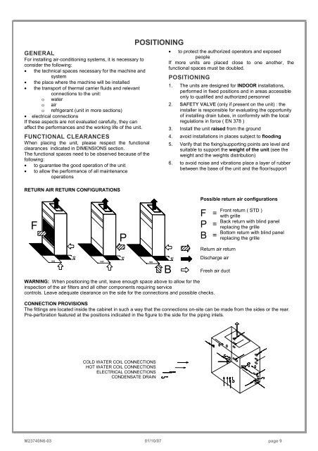
GENERALFor installing air-conditioning systems, it is necessary toconsider the following:• the technical spaces necessary for the machine andsystem• the place where the machine will be installed• the transport of thermal carrier fluids and relevantconnections to the unit:o watero airo refrigerant (unit in more sections)• electrical connectionsIf these aspects are not evaluated carefully, they canaffect the performances and the working life of the unit.FUNCTIONAL CLEARANCESWhen placing the unit, please respect the functionalclearances indicated in DIMENSIONS section.The functional spaces need to be observed because of thefollowing:• to guarantee the good operation of the unit• to allow the performance of all maintenanceoperationsRETURN AIR RETURN CONFIGURATIONSF10004001000P400POSITIONING1000• to protect the authorized operators and exposedpeopleIf more units are placed close to one another, thefunctional spaces must be doubled.POSITIONING1. The units are designed for INDOOR installations,performed in fixed positions and in areas accessibleonly to qualified and authorized personnel2. SAFETY VALVE (only if present on the unit) : theinstaller is responsible for evaluating the opportunityof installing drain tubes, in conformity with the localregulations in force ( EN 378 )3. Install the unit raised from the ground4. avoid installations in places subject to flooding5. Verify that the fixing/supporting points are level andsuitable to support the weight of the unit (see theweight and the weights distribution)6. to avoid noise and vibrations place a layer of rubberbetween the base of the unit and the floor/support400BPossible return air configurationsF =P =B =Return air returnDischarge airFresh air ductWARNING: When positioning the unit, leave enough space above to allow for theinspection of the air filters and all other components requiring servicecontrols. Leave adequate clearance on the side for the connections and possible checks.Front return ( STD )with grilleBack return with blind panelreplacing the grilleBottom return with blind panelreplacing the grilleCONNECTION PROVISIONSThe fittings are located inside the cabinet in such a way that the connections on-site can be made from the sides or the rear.Pre-perforation featured at the positions indicated in the figure to the side for the piping inlets.COLD WATER COIL CONNECTIONSHOT WATER COIL CONNECTIONSELECTRICAL CONNECTIONSCONDENSATE DRAINM23740N6-03 01/10/07 page 9