CF-V 31-41-51-71-91-101- 121-142-182-202-242 - Delta-Temp
CF-V 31-41-51-71-91-101- 121-142-182-202-242 - Delta-Temp
CF-V 31-41-51-71-91-101- 121-142-182-202-242 - Delta-Temp
You also want an ePaper? Increase the reach of your titles
YUMPU automatically turns print PDFs into web optimized ePapers that Google loves.
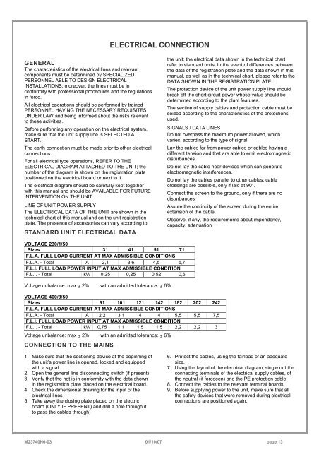
ELECTRICAL CONNECTIONGENERALThe characteristics of the electrical lines and relevantcomponents must be determined by SPECIALIZEDPERSONNEL ABLE TO DESIGN ELECTRICALINSTALLATIONS; moreover, the lines must be inconformity with professional procedures and the regulationsin force.All electrical operations should be performed by trainedPERSONNEL HAVING THE NECESSARY REQUISITESUNDER LAW and being informed about the risks relevantto these activities.Before performing any operation on the electrical system,make sure that the unit supply line is SELECTED ATSTART.The earth connection must be made prior to other electricalconnections.For all electrical type operations, REFER TO THEELECTRICAL DIAGRAM ATTACHED TO THE UNIT; thenumber of the diagram is shown on the registration platepositioned on the electrical board or next to it.The electrical diagram should be carefully kept togetherwith this manual and should be AVAILABLE FOR FUTUREINTERVENTION ON THE UNIT.LINE OF UNIT POWER SUPPLYThe ELECTRICAL DATA OF THE UNIT are shown in thetechnical chart of this manual and on the unit registrationplate. The presence of accessories can vary according toSTANDARD UNIT ELECTRICAL DATAthe unit; the electrical data shown in the technical chartrefer to standard units. In the event of differences betweenthe data of the registration plate and the data shown in thismanual, as well as in the technical chart, please refer to theDATA SHOWN IN THE REGISTRATION PLATE.The protection device of the unit power supply line shouldbreak off the short circuit power whose value should bedetermined according to the plant features.The section of supply cables and protection cable must beseized according to the characteristics of the protectionsused.SIGNALS / DATA LINESDo not overpass the maximum power allowed, whichvaries, according to the type of signal.Lay the cables far from power cables or cables having adifferent tension and that are able to emit electromagneticdisturbances.Do not lay the cable near devices which can generateelectromagnetic interferences.Do not lay the cables parallel to other cables; cablecrossings are possible, only if laid at 90°.Connect the screen to the ground, only if there are nodisturbancesAssure the continuity of the screen during the entireextension of the cable.Observe, if any, the requirements about impendency,capacity, attenuationVOLTAGE 230/1/50Sizes <strong>31</strong> <strong>41</strong> <strong>51</strong> <strong>71</strong>F.L.A. FULL LOAD CURRENT AT MAX ADMISSIBLE CONDITIONSF.L.A. - Total A 2,1 3,6 4,5 5,7F.L.I. FULL LOAD POWER INPUT AT MAX ADMISSIBLE CONDITIONF.L.I. - Total kW 0,25 0,25 0,52 0,6Voltage unbalance: max ± 2% with an admitted tolerance: ± 6%VOLTAGE 400/3/50Sizes <strong>91</strong> <strong>101</strong> <strong>121</strong> <strong>142</strong> <strong>182</strong> <strong>202</strong> <strong>242</strong>F.L.A. FULL LOAD CURRENT AT MAX ADMISSIBLE CONDITIONSF.L.A. - Total A 2,2 3,1 4 4 5,5 5,5 7,5F.L.I. FULL LOAD POWER INPUT AT MAX ADMISSIBLE CONDITIONF.L.I. - Total kW 0,75 1,1 1,5 1,5 2,2 2,2 3Voltage unbalance: max ± 2% with an admitted tolerance: ± 6%CONNECTION TO THE MAINS1. Make sure that the sectioning device at the beginning ofthe unit’s power line is opened, locked and equippedwith a signal.2. Open the general line disconnecting switch (if present)3. Verify that the net is in conformity with the data shownin the registration plate placed on the electrical board.4. Check the dimensional drawing for the input of theelectrical lines5. Take away the closing plate placed on the electricboard (ONLY IF PRESENT) and drill a hole through itto pass the cables through)6. Protect the cables, using the fairlead of an adequatesize.7. Using the layout of the electrical diagram, single out theconnecting terminals of the electrical supply cables, ofthe neutral (if foreseen) and the PE protection cable8. Connect the cables to the relevant terminal boards9. Before supplying power to the unit, make sure that allthe safety devices that were removed during electricalconnections are positioned again.M23740N6-03 01/10/07 page 13


