CF-V 31-41-51-71-91-101- 121-142-182-202-242 - Delta-Temp
CF-V 31-41-51-71-91-101- 121-142-182-202-242 - Delta-Temp
CF-V 31-41-51-71-91-101- 121-142-182-202-242 - Delta-Temp

You also want an ePaper? Increase the reach of your titles
YUMPU automatically turns print PDFs into web optimized ePapers that Google loves.
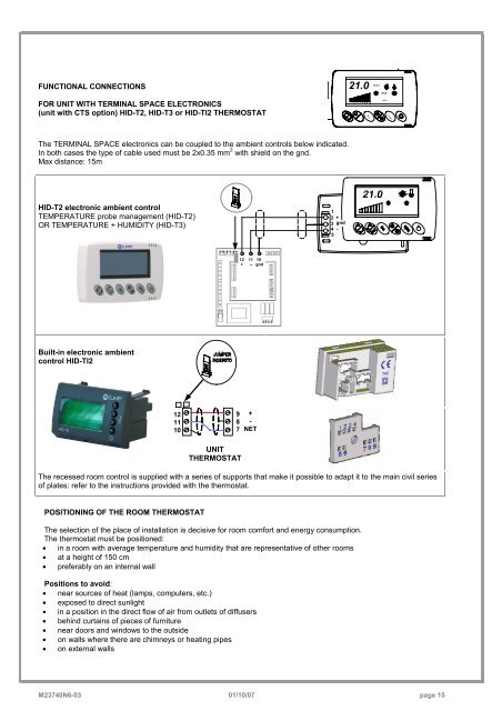
FUNCTIONAL CONNECTIONSFOR UNIT WITH TERMINAL SPACE ELECTRONICS(unit with CTS option) HID-T2, HID-T3 or HID-TI2 THERMOSTAT21.0REMOTEE c oECOAUTOC le a nThe TERMINAL SPACE electronics can be coupled to the ambient controls below indicated.In both cases the type of cable used must be 2x0.35 mm 2 with shield on the gnd.Max distance: 15mHID-T2 electronic ambient controlTEMPERATURE probe management (HID-T2)OR TEMPERATURE + HUMIDITY (HID-T3)12 +3 gnd4 -<strong>51</strong>2 11 10+ -- gndBuilt-in electronic ambientcontrol HID-TI2<strong>121</strong>110987+-NETUNITTHERMOSTATThe recessed room control is supplied with a series of supports that make it possible to adapt it to the main civil seriesof plates: refer to the instructions provided with the thermostat.POSITIONING OF THE ROOM THERMOSTATThe selection of the place of installation is decisive for room comfort and energy consumption.The thermostat must be positioned:• in a room with average temperature and humidity that are representative of other rooms• at a height of 150 cm• preferably on an internal wallPositions to avoid:• near sources of heat (lamps, computers, etc.)• exposed to direct sunlight• in a position in the direct flow of air from outlets of diffusers• behind curtains of pieces of furniture• near doors and windows to the outside• on walls where there are chimneys or heating pipes• on external wallsM23740N6-03 01/10/07 page 15