WATER CONNECTIONSGENERALPiping must be designed with the least possible number ofbends and head variations. If the pressure chute of theinstallation is above the useful prevalence of the pump, thewater delivery capacity is reduced as well as, as aconsequence, the thermal exchange and the yield.INTERCEPTING VALVESInstall on the input and output of the user parts(exchangers, coils, humidifiers, etc) So that it will bepossible to carry out all the service operations and possiblesubstitutions without emptying the installation.PRESSURE AND TEMPERATURE INDICATORInstall on the input and output of the user parts(exchangers, coils, humidifiers, etc) So that it will bepossible to carry out all the service operations.AUTOMATIC OR MANUAL ESCAPE VALVESInstall the highest points of tubes in a way that the air canescape form the circuit.BLEEDING COCKInstall them at the lowest points of the circuit, so as to allowemptying.LEAKAGE TESTSBefore performing the insulation of the tubes, carry out aleakage test.TUBE INSULATIONAll tubes of water must be insulated so that to avoid theformation of condensation and thermal dispersions alongthe tubes themselves. Verify that the insulation is thevapour coil type. The connections for the air escape and forthe emptying must be out of the insulating thickness toassure the accessibility.CONNECTIONS SUPPORTSThe weight of the hydraulic connections must be supportedin the exterior of the unit so as not to stress the connectionsof user devices (exchangers, coils, humidifiers, etc ) .ANTI-VIBRATION DEVICESIn case of units with anti-vibration devices, it is necessary toassemble elastic joints, even on water connections.RISK OF FREEZEIf the unit and the relevant water connections are subject totemperatures near 0°C:• mix the water of the system with glycol• protect the tubes with heating cables under the tubesinsulation• empty the system by verifying that:ono taps are closed so they can not trap the water,even after emptyingo there are no low points where the water canstagnate even after emptying; blow if necessaryINSTALLATION EMPTYINGThe refilling of the water present in the installation increasethe oxidation phenomena and lime deposits.If necessary empty only the interested system section andanyway empty or refill the installation if necessary .EXPANSION TANKThe installation must be kept at the right pressure by bothan expansion tank and a combined valve of pressurereduction and discharge; if the components are present onthe unit, they must be installed on the installation. Theexpansion tank must be dimensioned in function of thewater in the installation.MAX. WORKING PRESSURE =10BarARIES EFFECTS AND AIR BUBBLES CAN PRODUCETHE OVERCOMING AND CAUSE WATER DROPS.CONDENSATE DISCHARGE CONNECTION.1. The condensate must be dispersed to avoid damages topersons and property.2. Unit discharge fitting : the connection must avoid thetransmission of mechanical stresses and must beperformed paying attention to avoid the damaging of theunit discharge fitting3. Make a trap that, eliminating the depression caused bythe fan, stops the return of gas from the discharge pipe(see the figure).4. Connect the condensate discharge to a rainwater drain.Do NOT use sewerage drains, so as to avoid the returnof odours if the water contained in the trap evaporates.5. Finally, check that the condensate will drain correctly bypouring water into the tray stud.6. RISK OF FREEZE : If the unit operates in cooling withoutside temperatures lower than 0°C, value thepossibility that the condensate can freeze blocking thedownflow and provoking flooding. Use heat cables orother devices to guarantee the disposal.M23740N6-03 01/10/07 page 10
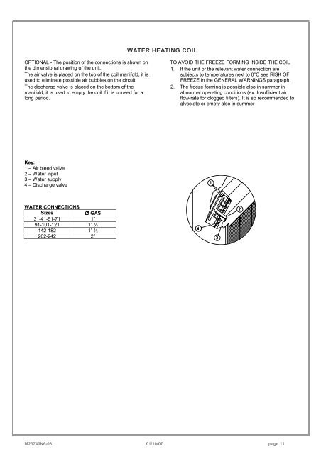
WATER HEATING COILOPTIONAL - The position of the connections is shown onthe dimensional drawing of the unit.The air valve is placed on the top of the coil manifold, it isused to eliminate possible air bubbles on the circuit.The discharge valve is placed on the bottom of themanifold, it is used to empty the coil if it is unused for along period.TO AVOID THE FREEZE FORMING INSIDE THE COIL1. If the unit or the relevant water connection aresubjects to temperatures next to 0°C see RISK OFFREEZE in the GENERAL WARNINGS paragraph.2. The freeze forming is possible also in summer inabnormal operating conditions (ex. Insufficient airflow-rate for clogged filters). It is so recommended toglycolate or empty also in summerKey:1 – Air bleed valve2 – Water input3 – Water supply4 – Discharge valveWATER CONNECTIONSSizes∅ GAS<strong>31</strong>-<strong>41</strong>-<strong>51</strong>-<strong>71</strong> 1”<strong>91</strong>-<strong>101</strong>-<strong>121</strong> 1” ¼<strong>142</strong>-<strong>182</strong> 1” ½<strong>202</strong>-<strong>242</strong> 2”M23740N6-03 01/10/07 page 11