Installatiefiche - Delta-Temp
Installatiefiche - Delta-Temp
Installatiefiche - Delta-Temp
- No tags were found...

Create successful ePaper yourself
Turn your PDF publications into a flip-book with our unique Google optimized e-Paper software.
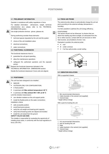
POSITIONING 33.1 PRELIMINARY INFORMATION 3.4 FRESH AIR PROBEOperate in compliance with safety regulations in force.For detailed information (dimensions, weight, technicalcharacteristics etc.) please refer to the TECHNICALINFORMATION section.Use single protection devices : gloves, glasses etc.During positioning consider these elements :technical spaces requested by the unit and the systemchoice of the unit installation placeelectrical connectionswater connections3.2 FUNCTIONAL CLEARANCESThe external probe allows to automatically change the unit setpoint according to the external enthalpy (temperature +humidity).It is then possible to optimize the unit energy efficiency.POSITIONINGThe sensor should not be influenced by factors that candistort the reading (eg direct sunlight, air exhausted from thefan or other sources, contact with the unit structure or otherheat sources, accumulations of snow / ice).Examples to position the external probe :ABCroofunder a terraceif at free wall provide a small roofingThe functional clearances have to :guarantee the unit good operatingallow the maintenance operationssafeguard the authorized operators and the exposedpersonRespect the functional clearances indicated in theTECHNICAL INFORMATION - DIMENSIONS section.Double the functional clearances if more units are aligned.3.3 POSITIONING3.5 VIBRATION ISOLATORSWith a supported chassisThe unit has been designed to be installed :INDOOROUTDOOR (ONLY EN CONFIGURATION)in fixed positionin premises with Max ambient temperature= 40 °Cin premises with Max ambient RH = 50% at 40 °CLimit the vibration transmission:use vibration isolators on the unit support pointsinstall the flexible joints on the water connections.Installation criteria:safe accessible positionavoid flood-prone places;verify the unit weight and bearing point capacity;verify that all bearing points are aligned and levelledinstall the unit raised from the groundSAFETY VALVE GAS SIDEThe installer is responsible for evaluating the opportunity ofinstalling drain tubes, in conformity with the local regulations inforce ( EN 378 )1. Min recommended dimensions2. Cable brackets in the cement (not supplied)3. Cement base* height without chargeWith a jack for leveling the unit1. min recommended dimensions2. jack for leveling the unit3. plate4. cable brackets in the cement (not supplied)5. Cement base* height without charge7