Installatiefiche - Delta-Temp
Installatiefiche - Delta-Temp
Installatiefiche - Delta-Temp
- No tags were found...
Create successful ePaper yourself
Turn your PDF publications into a flip-book with our unique Google optimized e-Paper software.
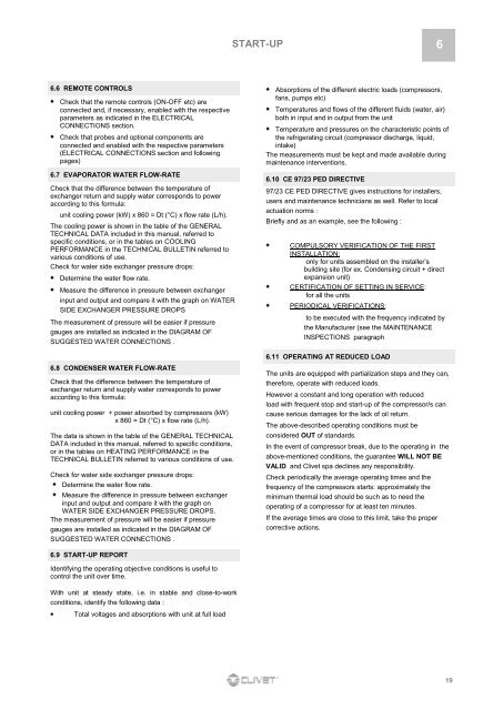
START-UP 66.6 REMOTE CONTROLSCheck that the remote controls (ON-OFF etc) areconnected and, if necessary, enabled with the respectiveparameters as indicated in the ELECTRICALCONNECTIONS section.Check that probes and optional components areconnected and enabled with the respective parameters(ELECTRICAL CONNECTIONS section and followingpages)6.7 EVAPORATOR WATER FLOW-RATECheck that the difference between the temperature ofexchanger return and supply water corresponds to poweraccording to this formula:unit cooling power (kW) x 860 = Dt (°C) x flow rate (L/h).The cooling power is shown in the table of the GENERALTECHNICAL DATA included in this manual, referred tospecific conditions, or in the tables on COOLINGPERFORMANCE in the TECHNICAL BULLETIN referred tovarious conditions of use.Check for water side exchanger pressure drops:Determine the water flow rate.Measure the difference in pressure between exchangerinput and output and compare it with the graph on WATERSIDE EXCHANGER PRESSURE DROPSThe measurement of pressure will be easier if pressuregauges are installed as indicated in the DIAGRAM OFSUGGESTED WATER CONNECTIONS .Absorptions of the different electric loads (compressors,fans, pumps etc)<strong>Temp</strong>eratures and flows of the different fluids (water, air)both in input and in output from the unit<strong>Temp</strong>erature and pressures on the characteristic points ofthe refrigerating circuit (compressor discharge, liquid,intake)The measurements must be kept and made available duringmaintenance interventions.6.10 CE 97/23 PED DIRECTIVE97/23 CE PED DIRECTIVE gives instructions for installers,users and maintenance technicians as well. Refer to localactuation norms :Briefly and as an example, see the following :COMPULSORY VERIFICATION OF THE FIRSTINSTALLATION:only for units assembled on the installer’sbuilding site (for ex. Condensing circuit + directexpansion unit)CERTIFICATION OF SETTING IN SERVICE:for all the unitsPERIODICAL VERIFICATIONS:to be executed with the frequency indicated bythe Manufacturer (see the MAINTENANCEINSPECTIONS paragraph6.11 OPERATING AT REDUCED LOAD6.8 CONDENSER WATER FLOW-RATECheck that the difference between the temperature ofexchanger return and supply water corresponds to poweraccording to this formula:unit cooling power + power absorbed by compressors (kW)x 860 = Dt (°C) x flow rate (L/h).The data is shown in the table of the GENERAL TECHNICALDATA included in this manual, referred to specific conditions,or in the tables on HEATING PERFORMANCE in theTECHNICAL BULLETIN referred to various conditions of use.Check for water side exchanger pressure drops:Determine the water flow rate.Measure the difference in pressure between exchangerinput and output and compare it with the graph onWATER SIDE EXCHANGER PRESSURE DROPS.The measurement of pressure will be easier if pressuregauges are installed as indicated in the DIAGRAM OFSUGGESTED WATER CONNECTIONS .The units are equipped with partialization steps and they can,therefore, operate with reduced loads.However a constant and long operation with reducedload with frequent stop and start-up of the compressor/s cancause serious damages for the lack of oil return.The above-described operating conditions must beconsidered OUT of standards.In the event of compressor break, due to the operating in theabove-mentioned conditions, the guarantee WILL NOT BEVALID and Clivet spa declines any responsibility.Check periodically the average operating times and thefrequency of the compressors starts: approximately theminimum thermal load should be such as to need theoperating of a compressor for at least ten minutes.If the average times are close to this limit, take the propercorrective actions.6.9 START-UP REPORTIdentifying the operating objective conditions is useful tocontrol the unit over time.With unit at steady state, i.e. in stable and close-to-workconditions, identify the following data :Total voltages and absorptions with unit at full load19


