Technische fiche - Delta-Temp
Technische fiche - Delta-Temp
Technische fiche - Delta-Temp

Create successful ePaper yourself
Turn your PDF publications into a flip-book with our unique Google optimized e-Paper software.
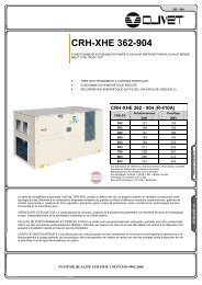
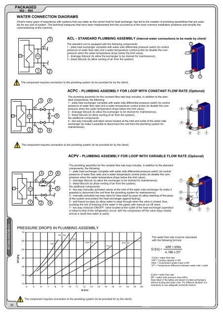
BT08L005GB-01DP [kPa]PACKAGED362 - 904WATER CONNECTION DIAGRAMSClivet's many years of experience with systems that use water as the carrier fluid for heat exchange, has led to the creation of plumbing assemblies that are suitablefor any sort of system. The technical measures that have been implemented limit the occurrence of the most common installation problems and simplify thecommissioning of the machine.TPD3ACL - STANDARD PLUMBING ASSEMBLY (Internal water connections to be made by client)The standard unit is equipped with the following components:1 - plate heat exchanger complete with water side differential pressure switch (to controlpresence of water flow rate) and a water temperature control probe (to disable the compressorswhen the water temperature drops below the limit value);2 - drainage bibcock (to allow the exchanger to be drained for maintenance);3 - bleed bibcock (to allow venting of air from the system);3122 1The component requires connection to the plumbing system (to be provided for by the client).ACPC - PLUMBING ASSEMBLY FOR LOOP WITH CONSTANT FLOW RATE (Optional)TPD132445The plumbing assembly for the constant flow rate loop includes, in addition to the standardcomponents, the following:1 - plate heat exchanger complete with water side differential pressure switch (to controlpresence of water flow rate) and a water temperature control probe (to disable the compressorswhen the water temperature drops below the limit value);2 - drainage bibcock (to allow the exchanger to be drained for maintenance);3 - bleed bibcock (to allow venting of air from the system);the additional components:4 - two-way manually activated valves located at the inlet and outlet of the water sideexchanger (to make it possible to disconnect the unit from the plumbing system formaintenance);The component requires connection to the plumbing system (to be provided for by the client).ACPV - PLUMBING ASSEMBLY FOR LOOP WITH VARIABLE FLOW RATE (Optional)TPD1327465The plumbing assembly for the variable flow rate loop includes, in addition to the standardcomponents, the following:1 - plate heat exchanger complete with water side differential pressure switch (to controlpresence of water flow rate) and a water temperature control probe (to disable the compressorswhen the water temperature drops below the limit value);2 - drainage bibcock (to allow the exchanger to be drained for maintenance);3 - bleed bibcock (to allow venting of air from the system);the additional components:4 - two-way manually activated valves at the inlet of the water side exchanger (to make itpossible to disconnect the unit from the plumbing system for maintenance);5 - manually activated two-way valve for loop wash by-pass (to allow washing of the pipesof the system and protect the heat exchanger against fouling);6 - anti-freeze by-pass (to allow water to seep through when the valve is closed, thusavoiding the risk of freezing of the water in the pipes) with manual cut-off valve;7 - two-way motorize ON/OFF valve located at the outlet of the heat exchanger (operationis linked to that of the refrigeration circuit: with the compressor off the valve stays closedand as a result less water is used);PRESSURE DROPS IN PLUMBING ASSEMBLY70402-45246460524-604 804-90436270450The water flow rate must be calculatedwith the following formulaQ [l/s] =kWf + kWe4,186 x DT4030Q [l/s] = water flow ratekWf = Cooling capacity in kWkWe = Compressor power input in kWDT = <strong>Temp</strong>erature difference between water inlet / outlet20104 5 6 7 8 9 10 11 12 13 14 15 16 17 18 19 20Q [l/s]Q [l/s] = water flow rateDP = water-side pressure drop (kPa)Data listed in the tables are based on plate exchangerswithout fouling and clean coils. For different situation it isnecessary to use adeguate correction factors.The component requires connection to the plumbing system (to be provided for by the client).46