Technische fiche - Delta-Temp
Technische fiche - Delta-Temp
Technische fiche - Delta-Temp

You also want an ePaper? Increase the reach of your titles
YUMPU automatically turns print PDFs into web optimized ePapers that Google loves.
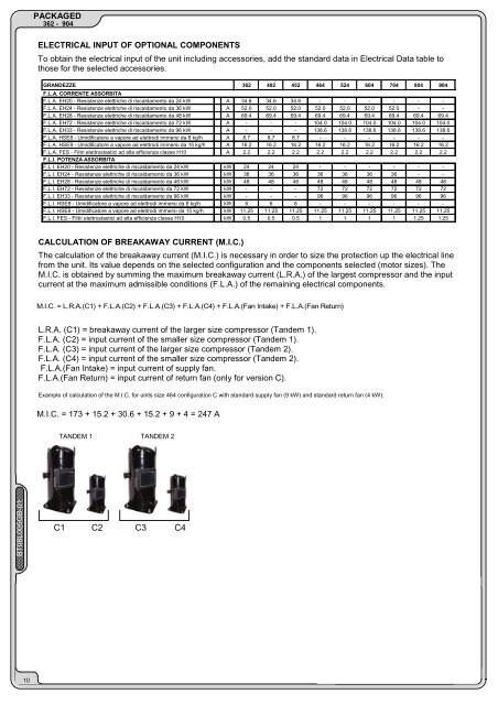
BT08L005GB-01PACKAGED362 - 904ELECTRICAL INPUT OF OPTIONAL COMPONENTSTo obtain the electrical input of the unit including accessories, add the standard data in Electrical Data table tothose for the selected accessories.GRANDEZZE 362 402 452 464 524 604 704 804 904F.L.A. CORRENTE ASSORBITAF.L.A. EH20 - Resistenze elettriche di riscaldamento da 24 kWF.L.A. EH24 - Resistenze elettriche di riscaldamento da 36 kWF.L.A. EH28 - Resistenze elettriche di riscaldamento da 48 kWF.L.A. EH72 - Resistenze elettriche di riscaldamento da 72 kWF.L.A. EH33 - Resistenze elettriche di riscaldamento da 96 kWF.L.A. HSE8 - Umidificatore a vapore ad elettrodi immersi da 8 kg/hF.L.A. HSE9 - Umidificatore a vapore ad elettrodi immersi da 15 kg/hF.L.A. FES - Filtri elettrostastici ad alta efficienza classe H10F.L.I. POTENZA ASSORBITAF.L.I. EH20 - Resistenze elettriche di riscaldamento da 24 kWF.L.I. EH24 - Resistenze elettriche di riscaldamento da 36 kWF.L.I. EH28 - Resistenze elettriche di riscaldamento da 48 kWF.L.I. EH72 - Resistenze elettriche di riscaldamento da 72 kWF.L.I. EH33 - Resistenze elettriche di riscaldamento da 96 kWF.L.I. HSE8 - Umidificatore a vapore ad elettrodi immersi da 8 kg/hF.L.I. HSE9 - Umidificatore a vapore ad elettrodi immersi da 15 kg/hF.L.I. FES - Filtri elettrostastici ad alta efficienza classe H10A 34.6 34.6 34.6 - - - - - -A 52.0 52.0 52.0 52.0 52.0 52.0 52.0 - -A 69.4 69.4 69.4 69.4 69.4 69.4 69.4 69.4 69.4A - - - 104.0 104.0 104.0 104.0 104.0 104.0A - - - 138.6 138.6 138.6 138.6 138.6 138.6A 8.7 8.7 8.7 - - - - - -A 16.2 16.2 16.2 16.2 16.2 16.2 16.2 16.2 16.2A 2.2 2.2 2.2 2.2 2.2 2.2 2.2 2.2 2.2kW 24 24 24 - - - - - -kW 36 36 36 36 36 36 36 - -kW 48 48 48 48 48 48 48 48 48kW - - - 72 72 72 72 72 72kW - - - 96 96 96 96 96 96kW 6 6 6 - - - - - -kW 11.25 11.25 11.25 11.25 11.25 11.25 11.25 11.25 11.25kW 0.5 0.5 0.5 1 1 1 1 1.25 1.25CALCULATION OF BREAKAWAY CURRENT (M.I.C.)The calculation of the breakaway current (M.I.C.) is necessary in order to size the protection up the electrical linefrom the unit. Its value depends on the selected configuration and the components selected (motor sizes). TheM.I.C. is obtained by summing the maximum breakaway current (L.R.A.) of the largest compressor and the inputcurrent at the maximum admissible conditions (F.L.A.) of the remaining electrical components.M.I.C. = L.R.A.(C1) + F.L.A.(C2) + F.L.A.(C3) + F.L.A.(C4) + F.L.A.(Fan Intake) + F.L.A.(Fan Return)L.R.A. (C1) = breakaway current of the larger size compressor (Tandem 1).F.L.A. (C2) = input current of the smaller size compressor (Tandem 1).F.L.A. (C3) = input current of the larger size compressor (Tandem 2).F.L.A. (C4) = input current of the smaller size compressor (Tandem 2).F.L.A.(Fan Intake) = input current of supply fan.F.L.A.(Fan Return) = input current of return fan (only for version C).Example of calculation of the M.I.C. for units size 464 configuration C with standard supply fan (9 kW) and standard return fan (4 kW):M.I.C. = 173 + 15.2 + 30.6 + 15.2 + 9 + 4 = 247 ATANDEM 1 TANDEM 2C1 C2 C3 C410