TUNNEL ENGINEERING
TUNNEL ENGINEERING
TUNNEL ENGINEERING

Create successful ePaper yourself
Turn your PDF publications into a flip-book with our unique Google optimized e-Paper software.
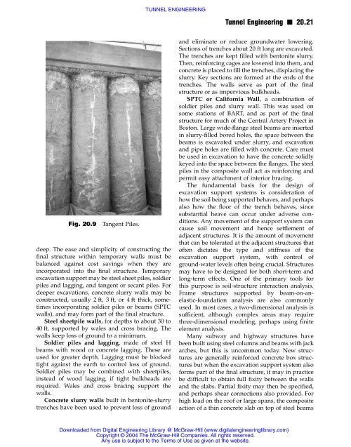
Fig. 20.9 Tangent Piles.<br />
deep. The ease and simplicity of constructing the<br />
final structure within temporary walls must be<br />
balanced against cost savings when they are<br />
incorporated into the final structure. Temporary<br />
excavation support may be steel sheet piles, soldier<br />
piles and lagging, and tangent or secant piles. For<br />
deeper excavations, concrete slurry walls may be<br />
constructed, usually 2 ft, 3 ft, or 4 ft thick, sometimes<br />
incorporating soldier piles or beams (SPTC<br />
walls), and may form part of the final structure.<br />
Steel sheetpile walls, for depths to about 30 to<br />
40 ft, supported by wales and cross bracing. The<br />
walls keep loss of ground to a minimum.<br />
Soldier piles and lagging, made of steel H<br />
beams with wood or concrete lagging. These are<br />
used for greater depth. Lagging must be blocked<br />
tight against the earth to control loss of ground.<br />
Soldier piles may be combined with sheetpiles,<br />
instead of wood lagging, if tight bulkheads are<br />
required. Wales and cross bracing support the<br />
walls.<br />
Concrete slurry walls built in bentonite-slurry<br />
trenches have been used to prevent loss of ground<br />
<strong>TUNNEL</strong> <strong>ENGINEERING</strong><br />
Tunnel Engineering n 20.21<br />
and eliminate or reduce groundwater lowering.<br />
Sections of trenches about 20 ft long are excavated.<br />
The trenches are kept filled with bentonite slurry.<br />
Then, reinforcing cages are lowered into them, and<br />
concrete is placed to fill the trenches, displacing the<br />
slurry. Key sections are formed at the ends of the<br />
trenches. The walls serve as part of the final<br />
structure or as impervious bulkheads.<br />
SPTC or California Wall, a combination of<br />
soldier piles and slurry wall. This was used on<br />
some stations of BART, and as part of the final<br />
structure for much of the Central Artery Project in<br />
Boston. Large wide-flange steel beams are inserted<br />
in slurry-filled bored holes, the space between the<br />
beams is excavated under slurry, and excavation<br />
and pipe holes are filled with concrete. Care must<br />
be used in excavation to have the concrete solidly<br />
keyed into the space between the flanges. The steel<br />
piles in the composite wall act as reinforcing and<br />
permit easy attachment of interior bracing.<br />
The fundamental basis for the design of<br />
excavation support systems is consideration of<br />
how the soil being supported behaves, and perhaps<br />
also how the floor of the trench behaves, since<br />
substantial heave can occur under adverse conditions.<br />
Any movement of the support system can<br />
cause soil movement and hence settlement of<br />
adjacent structures. It is the amount of movement<br />
that can be tolerated at the adjacent structures that<br />
often dictates the type and stiffness of the<br />
excavation support system, with control of<br />
ground-water levels often being crucial. Structures<br />
may have to be designed for both short-term and<br />
long-term effects. One of the primary tools for<br />
this purpose is soil-structure interaction analysis.<br />
Frame structures supported by beam-on-anelastic-foundation<br />
analysis are also commonly<br />
used. In most cases, a two-dimensional analysis is<br />
sufficient, although complex areas may require<br />
three-dimensional modeling, perhaps using finite<br />
element analysis.<br />
Many subway and highway structures have<br />
been built using steel columns and beams with jack<br />
arches, but this is uncommon today. New structures<br />
are generally reinforced concrete box structures<br />
but when the excavation support system also<br />
forms part of the final structure, it may in practice<br />
be difficult to obtain full fixity between the walls<br />
and the slabs. Partial fixity may then be specified,<br />
and perhaps shear connections also provided. For<br />
high load on the roof or large spans, the composite<br />
action of a thin concrete slab on top of steel beams<br />
Downloaded from Digital Engineering Library @ McGraw-Hill (www.digitalengineeringlibrary.com)<br />
Copyright © 2004 The McGraw-Hill Companies. All rights reserved.<br />
Any use is subject to the Terms of Use as given at the website.