TUNNEL ENGINEERING
TUNNEL ENGINEERING
TUNNEL ENGINEERING

Create successful ePaper yourself
Turn your PDF publications into a flip-book with our unique Google optimized e-Paper software.
unless the rock is highly abrasive, causing<br />
excessive wear of drills.<br />
Too much information can never be provided<br />
for the engineer, to produce a realistic design, and<br />
for the contractors, to prepare sound bids. Even at<br />
best, unforeseen difficulties must be expected.<br />
In addition to geological surveys and borings<br />
(Art. 20.5), engineers may use electric-resistivity<br />
measurements and gamma-ray absorption for<br />
information on depth and characteristics of rock<br />
formations. Information also may be obtained from<br />
the U.S. Geological Survey, which has extended its<br />
scope and geophysical studies beyond the mining<br />
field. Where geological conditions are particularly<br />
hard to evaluate or are especially severe, exploratory<br />
pilot tunnels, about 10 10 ft, may be driven<br />
part way from each end or for the entire length of a<br />
tunnel, prior to final design and advertising of<br />
construction. TBMs may be used for pilot tunnels<br />
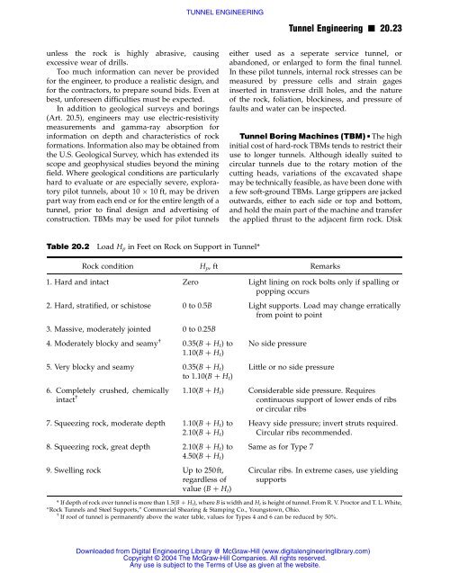
Table 20.2 Load Hp in Feet on Rock on Support in Tunnel*<br />
either used as a seperate service tunnel, or<br />
abandoned, or enlarged to form the final tunnel.<br />
In these pilot tunnels, internal rock stresses can be<br />
measured by pressure cells and strain gages<br />
inserted in transverse drill holes, and the nature<br />
of the rock, foliation, blockiness, and pressure of<br />
faults and water can be inspected.<br />
Tunnel Boring Machines (TBM) n The high<br />
initial cost of hard-rock TBMs tends to restrict their<br />
use to longer tunnels. Although ideally suited to<br />
circular tunnels due to the rotary motion of the<br />
cutting heads, variations of the excavated shape<br />
may be technically feasible, as have been done with<br />
a few soft-ground TBMs. Large grippers are jacked<br />
outwards, either to each side or top and bottom,<br />
and hold the main part of the machine and transfer<br />
the applied thrust to the adjacent firm rock. Disk<br />
Rock condition Hp, ft Remarks<br />
1. Hard and intact Zero Light lining on rock bolts only if spalling or<br />
popping occurs<br />
2. Hard, stratified, or schistose 0 to 0.5B Light supports. Load may change erratically<br />
from point to point<br />
3. Massive, moderately jointed 0 to 0.25B<br />
4. Moderately blocky and seamy †<br />
0.35(B þ Ht)to 1.10(B þ Ht)<br />
No side pressure<br />
5. Very blocky and seamy 0.35(B þ H t)<br />
to 1.10(B þ Ht)<br />
6. Completely crushed, chemically<br />
intact †<br />
<strong>TUNNEL</strong> <strong>ENGINEERING</strong><br />
7. Squeezing rock, moderate depth 1.10(B þ Ht) to<br />
2.10(B þ Ht)<br />
8. Squeezing rock, great depth 2.10(B þ Ht) to<br />
4.50(B þ Ht)<br />
9. Swelling rock Up to 250ft,<br />
regardless of<br />
value (B þ Ht)<br />
Little or no side pressure<br />
1.10(B þ H t) Considerable side pressure. Requires<br />
continuous support of lower ends of ribs<br />
or circular ribs<br />
Heavy side pressure; invert struts required.<br />
Circular ribs recommended.<br />
Same as for Type 7<br />
Tunnel Engineering n 20.23<br />
Circular ribs. In extreme cases, use yielding<br />
supports<br />
* If depth of rock over tunnel is more than 1.5(B þ Ht), where B is width and Ht is height of tunnel. From R. V. Proctor and T. L. White,<br />
“Rock Tunnels and Steel Supports,” Commercial Shearing & Stamping Co., Youngstown, Ohio.<br />
† If roof of tunnel is permanently above the water table, values for Types 4 and 6 can be reduced by 50%.<br />
Downloaded from Digital Engineering Library @ McGraw-Hill (www.digitalengineeringlibrary.com)<br />
Copyright © 2004 The McGraw-Hill Companies. All rights reserved.<br />
Any use is subject to the Terms of Use as given at the website.