TUNNEL ENGINEERING
TUNNEL ENGINEERING
TUNNEL ENGINEERING

You also want an ePaper? Increase the reach of your titles
YUMPU automatically turns print PDFs into web optimized ePapers that Google loves.
more economical because of their strength and<br />
ease of installation. These are made of I beams<br />
cold-rolled into shape. For small tunnels with<br />
circular arches, the sets may be continuous<br />
frames. In larger tunnels or for flat arches, the<br />
sets consist of separate posts and arches (Fig. 20.11).<br />
Where roof supports only are necessary, the<br />
arches may be supported on plates resting on<br />
rock ledges. Steel sections are usually uniform for<br />
the entire tunnel, and spacing of sets is varied<br />
according to rock loads. Normal spacing is 4 ft.<br />
but spacing may be reduced to 2 ft or increased to<br />
as much as 6 ft.<br />
The sets should be erected as soon as scaling of<br />
loose rock has been completed. Blocking should<br />
immediately be wedged between the steel and the<br />
rock surface at 3- to 5-ft intervals to prevent rock<br />
movement from starting. The steel frames should<br />
allow space at the crown, between the lower flange<br />
and the concrete surface, for a pipe for placing<br />
concrete.<br />
Timber or steel lagging should be placed<br />
between the sets. The amount of lagging depends<br />
on rock conditions. Lagging may be practically<br />
solid, or there may be gaps of various widths<br />
between the sheets, as required by circumstances.<br />
Badly fragmented rock may require metal panning<br />
between sets if water is present. The pans are made<br />
<strong>TUNNEL</strong> <strong>ENGINEERING</strong><br />
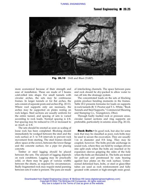
Fig. 20.10 Drill and Blast (TARP).<br />
Tunnel Engineering n 20.25<br />
of interlocking channels. The space between pans<br />
and rock should be dry-packed to allow water to<br />
run off into the drainage system.<br />
The concentrated loads on the sets at blocking<br />
points produce bending moments in the frames.<br />
Table 20.2 presents formulas for loads on supports<br />
in rock tunnels (R. V. Proctor and T. L. White, “Rock<br />
Tunnels and Steel Supports,” Commercial Shearing<br />
and Stamping Co., Youngstown, Ohio).<br />
Through badly faulted rock or pressure areas,<br />
circular tunnel sections and ring supports are<br />
preferable, particularly in seismic areas (Fig. 20.12).<br />
Rock Bolts n In good rock, but also for some<br />
rock that may be classified as poor, rock bolts may<br />
be used to secure the excavation. They are usually<br />
1 in in diameter and 8 ft long. They may be<br />
coupled, however. The bolts provide anchorage in<br />
sound rock, where they are held by wedges driven<br />
into split ends when the bolts are inserted or by<br />
expansion sleeves gripping the sides of the hole<br />
when the bolts are threaded in. The bolts are tested<br />
for pull-out and prestressed by nuts bearing<br />
against face plates on the rock surface. Untensioned<br />
deformed bars, bolts, or steel or glass-fiber<br />
tubes are used as rock reinforcement and fully<br />
grouted with cement or high-strength resin grout.<br />
Downloaded from Digital Engineering Library @ McGraw-Hill (www.digitalengineeringlibrary.com)<br />
Copyright © 2004 The McGraw-Hill Companies. All rights reserved.<br />
Any use is subject to the Terms of Use as given at the website.