...Railway artillery - Personal Page of GENE SLOVER
...Railway artillery - Personal Page of GENE SLOVER
...Railway artillery - Personal Page of GENE SLOVER
You also want an ePaper? Increase the reach of your titles
YUMPU automatically turns print PDFs into web optimized ePapers that Google loves.
617<br />
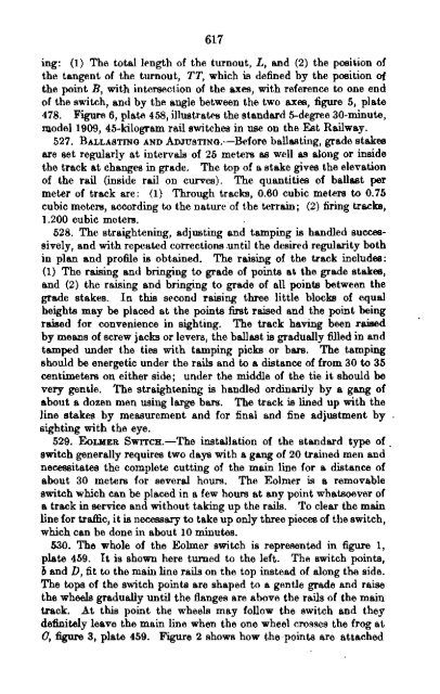
ing: (1) The total length <strong>of</strong> the turnout, L, and (2) the position <strong>of</strong><br />
the tangent <strong>of</strong> the turnout, TT, which is defined by the position <strong>of</strong><br />
the point B, with intersection <strong>of</strong> the axes, with reference to one end<br />
<strong>of</strong> the switch, and by the angle' between the two axes, figure 5, plate<br />
478. Figure 6, plate 458, illustrates the standard 5-degree 30-minute,<br />
DlodeI1909, 45-kilogram rail switches in use on the Est <strong>Railway</strong>.<br />
527. BALLASTING AND AD.rosTING.-Before ballasting, grade stakes<br />
are set regularly at intervals <strong>of</strong> 25 meters as well as along or inside<br />
the traCk at changes in grade. The top <strong>of</strong> a stake gives the elevation<br />
<strong>of</strong> the rail (inside rail on curves). The quantities <strong>of</strong> ballast per<br />
meter <strong>of</strong> track are: (1) Through tracks, 0.60 cubic meters to 0.75<br />
cubic meters, according to the nature"<strong>of</strong> the terrain; (2) firing tracks,<br />
1.200 cubic meters.<br />
528. The straightening, adjusting and tamping is handled successively,<br />
and with repeated corrections .until the desired regularity both<br />
in plan and pr<strong>of</strong>ile is obtained. The raising <strong>of</strong> the track includes:<br />
(1) The raising and bringing to grade <strong>of</strong> points at the grade stakes,<br />
and (2) the raising and bringing to grade <strong>of</strong> all points between the<br />
grade stakes. In this second raising three little blocks <strong>of</strong> equal<br />
heights may be placed at the points first raised and the point being<br />
raised for convenience in sighting. The track having been raised<br />
by means <strong>of</strong> screw jacks or levers, the ballast is gradually filled in and<br />
tamped under the ties with tamping picks or bars. The tamping<br />
should be energetic under the rails and to a distance <strong>of</strong> from 30 to 35<br />
centimeters on either side; under the middle <strong>of</strong> the tie it should be<br />
very gentle. The straightening is handled ordinarily by a gang <strong>of</strong><br />
about a dozen men using large bars. The track is lined up with the<br />
line stakes by measurement and for final and fine adjustment by<br />
sighting with the eye.<br />
529. EoLMER SWITCB.-The installation <strong>of</strong> the standard type <strong>of</strong> _<br />
switch generally requires two days with a gang <strong>of</strong> 20 trained men and<br />
necessitates the complete cutting <strong>of</strong> the main line for a distance <strong>of</strong><br />
about 30 meters for several hours. The Eolmer is a removable<br />
switch which can be placed in a few hours at any point whatsoever <strong>of</strong><br />
a track in service and without taking up the rails. To clear the main<br />
line for traffic, it is necessary to take up only three pieces <strong>of</strong> the switch,<br />
which can be done in about 10 minutes.<br />
530. The whole <strong>of</strong> the Eolmer switch is represented in figure 1,<br />
plate 459. It is shown here turned to the left. The switch points,<br />
band D, fit to the main line rails on the top instead <strong>of</strong> along the side.<br />
The tops <strong>of</strong> the switch points are shaped to a gentle grade and raise<br />
the wheels gradually until the flanges are above the rails <strong>of</strong> the main<br />
track. At this point the wheels may follow the switch and they<br />
definitely leave the main line when the one wheel crosses the frog at<br />
0, figure 3, plate 459. Figure 2 shows how the -points are attached<br />
Digitized by Coogle


