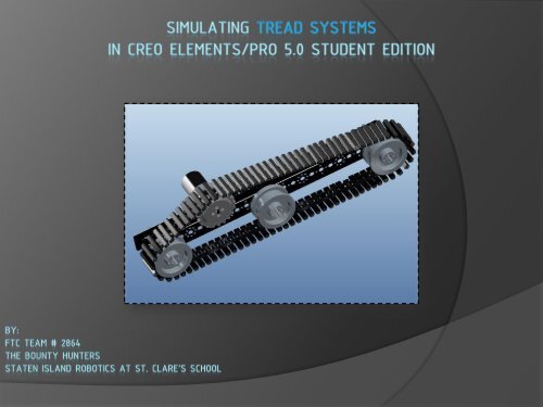
Simulating Tread Systems in Creo Elements/Pro 5.0
Simulating Tread Systems in Creo Elements/Pro 5.0
Simulating Tread Systems in Creo Elements/Pro 5.0

You also want an ePaper? Increase the reach of your titles
YUMPU automatically turns print PDFs into web optimized ePapers that Google loves.
Upon start<strong>in</strong>g <strong>Creo</strong>, go to: File New Assembly.<br />
File<br />
New<br />
<strong>Creo</strong> open<strong>in</strong>g w<strong>in</strong>dow<br />
Assembly
In Assembly, turn off datum planes, coord<strong>in</strong>ate systems, and 3D annotation<br />
display by click<strong>in</strong>g on each of their icons <strong>in</strong> the upper right hand corner.<br />
Datum Plane Icon “ON”<br />
Initial Assembly w<strong>in</strong>dow Modified Assembly w<strong>in</strong>dow<br />
3D Annotation Display<br />
Icon “ON”<br />
Coord<strong>in</strong>ate <strong>Systems</strong> Icon<br />
“ON”<br />
Datum Plane Icon<br />
“OFF”<br />
3D Annotation Display<br />
Icon “OFF”<br />
Coord<strong>in</strong>ate <strong>Systems</strong> Icon<br />
“OFF”
Press the Assembly icon on the right-hand side. Then, right click on<br />
2011_FTC_KOP Set Work<strong>in</strong>g Directory.<br />
Work<strong>in</strong>g<br />
Directory where<br />
2011_FTC_KOP<br />
components will<br />
now be found<br />
2011_FTC_KOP<br />
Set Work<strong>in</strong>g Directory<br />
Assembly Icon
Press the assembly icon and go to: Work<strong>in</strong>g Directory Tetrix_Kit_FTC. Then,<br />
open the 416 mm channel (downloaded at beg<strong>in</strong>n<strong>in</strong>g of power-po<strong>in</strong>t).<br />
Work<strong>in</strong>g Directory<br />
Channel-416mm.prt<br />
Tetrix_Kit_FTC<br />
Open 416 mm Channel
Set the 416 mm channel from the Automatic constra<strong>in</strong>t type to the Default constra<strong>in</strong>t type. The<br />
Default constra<strong>in</strong>t positions the part’s coord<strong>in</strong>ate system and the assembly’s coord<strong>in</strong>ate system so<br />
that they are relative to one another.<br />
Constra<strong>in</strong>t Options<br />
416 mm Channel on<br />
Automatic Constra<strong>in</strong>t<br />
416 mm Channel on<br />
Default Constra<strong>in</strong>t<br />
No other constra<strong>in</strong>t<br />
options – part is ready<br />
to go!<br />
Click on the green check<br />
to move on
Press the assembly icon, and go to: Work<strong>in</strong>g Directory Tetrix_Kit_FTC <br />
dc_motor_mount_2011.prt<br />
dc_motor_mount_2011.prt<br />
Open DC motor mount
Constra<strong>in</strong> the DC motor mount to the 416 mm channel us<strong>in</strong>g the Mate and Insert<br />
constra<strong>in</strong>ts.<br />
Us<strong>in</strong>g Mate constra<strong>in</strong>t<br />
Assembly: Surface of 416<br />
mm Channel<br />
Part: Bottom Surface of<br />
DC motor mount<br />
Us<strong>in</strong>g Insert constra<strong>in</strong>t<br />
Assembly: Small hole of 416<br />
mm Channel<br />
Part: Long Hole<br />
DC motor mount
Br<strong>in</strong>g out dc_motor_mount_2011.prt and constra<strong>in</strong> it to DC motor mount by us<strong>in</strong>g<br />
the P<strong>in</strong> connection set: 1. Axis Alignment, 2. Translation, 3. Rotation Axis.<br />
Axis Alignment<br />
Rotation Axis<br />
Translation
Br<strong>in</strong>g out tetrix_tt_idler_wheel_2011.prt and constra<strong>in</strong> it to DC motor by aga<strong>in</strong><br />
us<strong>in</strong>g the P<strong>in</strong> connection set: 1. Axis Alignment, 2. Translation, 3. Rotation Axis.<br />
Axis Alignment Translation<br />
Rotation Axis
Br<strong>in</strong>g out three axle_d-shaft_2011.prt and constra<strong>in</strong> each of them to different area of the channel<br />
by aga<strong>in</strong> us<strong>in</strong>g the P<strong>in</strong> connection set: 1. Axis Alignment, 2. Translation, 3. Rotation Axis.<br />
Constra<strong>in</strong><strong>in</strong>g first axle Constra<strong>in</strong><strong>in</strong>g second axle<br />
Constra<strong>in</strong><strong>in</strong>g third axle
Br<strong>in</strong>g out three idler wheels and constra<strong>in</strong> each of them to different areas of<br />
the channel by us<strong>in</strong>g the Mate and Insert constra<strong>in</strong>t types.<br />
Constra<strong>in</strong><strong>in</strong>g first idler wheel Constra<strong>in</strong><strong>in</strong>g second idler wheel<br />
Constra<strong>in</strong><strong>in</strong>g third idler wheel
Change Applications from Standard mode to Mechanism mode. (Standard mode is for<br />
creat<strong>in</strong>g assemblies; mechanism mode is for def<strong>in</strong><strong>in</strong>g servo motors and belt tracks.)<br />
Applications<br />
Mechanism (servo, belt)<br />
Standard Mode to Mechanism mode<br />
Standard (assembly)
In Mechanism mode, select Servo Motors icon <strong>in</strong> order to open the w<strong>in</strong>dow to def<strong>in</strong>e<br />
servo motors for the sprocket and idler wheels.<br />
Locat<strong>in</strong>g Servo Motors Icon and open<strong>in</strong>g w<strong>in</strong>dow<br />
Servo Motors Icon<br />
Servo Motors<br />
def<strong>in</strong>ition w<strong>in</strong>dow
Def<strong>in</strong>e the sprocket’s servo motor by select<strong>in</strong>g the connection axis (arrow) for the sprocket <strong>in</strong><br />
the Type box. Then, <strong>in</strong> the <strong>Pro</strong>file box, change position to velocity and A to equal 360 degrees<br />
per second.<br />
Type Box<br />
Def<strong>in</strong><strong>in</strong>g the servo motor for the sprocket<br />
Sprocket’s<br />
Connection Axis<br />
<strong>Pro</strong>file Box
Def<strong>in</strong>e the servo motors for each idler wheel <strong>in</strong> the Servo Motor w<strong>in</strong>dow.<br />
Def<strong>in</strong><strong>in</strong>g servo motor for first idler wheel Def<strong>in</strong><strong>in</strong>g servo motor for second idler wheel<br />
Def<strong>in</strong><strong>in</strong>g servo motor for first idler wheel
Select the Belt icon <strong>in</strong> order to open the w<strong>in</strong>dow for creat<strong>in</strong>g a belt track around the<br />
sprocket and idler wheels.<br />
Information for sett<strong>in</strong>g<br />
up belt track<br />
Locat<strong>in</strong>g Belt icon and open<strong>in</strong>g w<strong>in</strong>dow<br />
Belt Icon
To create the belt track, select the outer rim of the sprocket and then the outer rim<br />
of each of the idler wheels while hold<strong>in</strong>g down the ctrl key.<br />
Start<strong>in</strong>g belt track with sprocket and first idler wheel Add<strong>in</strong>g second idler wheel to belt track<br />
Add<strong>in</strong>g third idler wheel to belt track
To make the belt track an assembly part, first right click on Belt1 <strong>in</strong> the Model Tree,<br />
and then select Make Part.<br />
Turn<strong>in</strong>g the belt track <strong>in</strong>to an assembly part
The Component Create w<strong>in</strong>dow will appear for you to name the part you are mak<strong>in</strong>g for the belt<br />
track. Then, the Creation Options w<strong>in</strong>dow will appear for you to select a template for the belt<br />
track. (You can use the default, start_part_mmks.prt, which is already shown.<br />
Default template
In the form of the little sp<strong>in</strong> center, the belt part will be <strong>in</strong> your grasp. Place the belt part down,<br />
and select the Default constra<strong>in</strong>t to automatically place it over the sprocket and idler wheels.<br />
Constra<strong>in</strong><strong>in</strong>g the belt part<br />
Belt part represented by<br />
sp<strong>in</strong> center
Change Applications from Mechanism mode to Standard mode <strong>in</strong> order to get ready to<br />
constra<strong>in</strong> tread l<strong>in</strong>ks.<br />
Mechanism mode to Standard mode
Br<strong>in</strong>g out the tt_l<strong>in</strong>k_asm_2011.asm and select the Slot connection option, which<br />
features the Po<strong>in</strong>t on L<strong>in</strong>e constra<strong>in</strong>t.<br />
First Slot<br />
connection<br />
Initiat<strong>in</strong>g <strong>Tread</strong> L<strong>in</strong>k constra<strong>in</strong>ts<br />
<strong>Tread</strong> l<strong>in</strong>k
Under the Po<strong>in</strong>t on L<strong>in</strong>e constra<strong>in</strong>t, click on the “Select assembly item(s)” box. Then,<br />
select each of the seven parts of the belt while hold<strong>in</strong>g down the Ctrl key.<br />
“Select<br />
assembly<br />
item(s)”<br />
box<br />
Select<strong>in</strong>g Po<strong>in</strong>t on L<strong>in</strong>e assembly items of the first Slot set
Under the Po<strong>in</strong>t on L<strong>in</strong>e constra<strong>in</strong>t, click on “Select component item(s)” box. Then,<br />
select the mid-bottom vertex of the tread l<strong>in</strong>k as shown below.<br />
“Select<br />
component<br />
item(s)”<br />
box<br />
Select<strong>in</strong>g Po<strong>in</strong>t on L<strong>in</strong>e component item of the first Slot set<br />
Mid-bottom<br />
vertex
Select a second Slot connection option. Aga<strong>in</strong>, click on the “Select assembly item(s)” box under<br />
the Po<strong>in</strong>t on L<strong>in</strong>e constra<strong>in</strong>t and select the seven parts of the belt while hold<strong>in</strong>g down the ctrl<br />
key.<br />
Second Slot<br />
connection<br />
Select<strong>in</strong>g Po<strong>in</strong>t on L<strong>in</strong>e assembly items of the second Slot set
Aga<strong>in</strong>, under the Po<strong>in</strong>t on L<strong>in</strong>e constra<strong>in</strong>t, click on the “Select component item(s)” box<br />
and select the upper-bottom vertex of the tread l<strong>in</strong>k<br />
Select<strong>in</strong>g Po<strong>in</strong>t on L<strong>in</strong>e component item of the second Slot set<br />
Upper-bottom<br />
vertex
Select the green check after complet<strong>in</strong>g the first and second Slot connections. Then,<br />
switch from the Standard mode to Mechanism mode<br />
Display <strong>in</strong> Mechanism mode
Def<strong>in</strong>e tread l<strong>in</strong>k’s servo motor by select<strong>in</strong>g the second connection axis (slot) for the<br />
tread l<strong>in</strong>k <strong>in</strong> the Type box. Then, <strong>in</strong> the <strong>Pro</strong>file box, change position to velocity and<br />
A to equal 360 degrees per second.<br />
Def<strong>in</strong><strong>in</strong>g the servo motor for the tread l<strong>in</strong>k<br />
<strong>Tread</strong> l<strong>in</strong>k’s<br />
connection axis
Click on the Analysis Def<strong>in</strong>ition icon <strong>in</strong> order to open the w<strong>in</strong>dow for def<strong>in</strong><strong>in</strong>g how the<br />
movement of the tread l<strong>in</strong>k is shown.<br />
Start<strong>in</strong>g the Analysis Def<strong>in</strong>ition process<br />
Analysis<br />
Def<strong>in</strong>ition Icon
Set up the graphical display for the Analysis Def<strong>in</strong>ition by chang<strong>in</strong>g the End Time to 1, Frame Rate<br />
to 75, and M<strong>in</strong>imum Interval to 1/75 or .01333 …. (Also, experiment with different values.) Then,<br />
click on Run to view movement and OK to save.
Select the Playback icon <strong>in</strong> order to replay the analysis ran before.<br />
Open<strong>in</strong>g the Playback w<strong>in</strong>dow<br />
Analysis<br />
Def<strong>in</strong>ition Icon
Select Save <strong>in</strong> the Playbacks w<strong>in</strong>dow and the analysis will be set to save as a .pbk<br />
(mechanism playback) <strong>in</strong> the Tetrix_Kit_FTC folder.
Select Playback <strong>in</strong> the Playback w<strong>in</strong>dow and the Animate w<strong>in</strong>dow will appear. In the<br />
Animate w<strong>in</strong>dow, adjust factors <strong>in</strong>clud<strong>in</strong>g the speed and the animation’s direction.
In the Playback w<strong>in</strong>dow, select Capture to open the Capture w<strong>in</strong>dow. In the Capture<br />
w<strong>in</strong>dow, save the adjusted playback as a .mpg (video) and select OK.
Cont<strong>in</strong>ue connect<strong>in</strong>g and def<strong>in</strong><strong>in</strong>g servo motors for the tread l<strong>in</strong>ks. This may take a<br />
while; however, be patient!!! … all of the hard work will pay off <strong>in</strong> the end. (Then,<br />
work on the Playback when totally done.)<br />
<strong>Tread</strong> System for the Bounty Hunters FTC Team