Questa ADMS ds 4-11-12.indd - Mentor Graphics
Questa ADMS ds 4-11-12.indd - Mentor Graphics
Questa ADMS ds 4-11-12.indd - Mentor Graphics

Create successful ePaper yourself
Turn your PDF publications into a flip-book with our unique Google optimized e-Paper software.
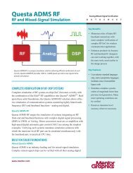
Analog-Digital Mixed-Signal Simulator<br />
<strong>Questa</strong> <strong>ADMS</strong><br />
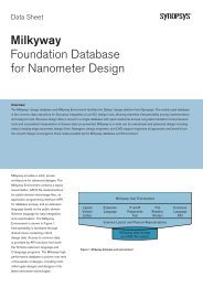
<strong>Questa</strong> <strong>ADMS</strong> is the de facto industry standard for the creation and verification<br />
of complex analog and mixed-signal designs.<br />
Mixed-Signal Simulator for Modern Design<br />
<strong>Questa</strong>® <strong>ADMS</strong> exten<strong>ds</strong> the <strong>Mentor</strong> <strong>Graphics</strong>® <strong>Questa</strong> verification<br />
environment across the digital/analog divide. Design and verification<br />
engineers use <strong>Questa</strong> <strong>ADMS</strong> to develop and prove complex analog and<br />
mixed-signal designs. <strong>Questa</strong> <strong>ADMS</strong> combines five high-performance<br />
simulation engines in one efficient tool and supports every major<br />
electronic simulation language and exchange standard.<br />
A Flexible Mixed-Signal Strategy<br />
System-level verification of modern SoC designs is mandatory because of<br />
the high cost of respins. But system-level verification presents a dilemma.<br />
Simulating with only digital models is fast but inaccurate, and simulating<br />
with only transistor level models is too slow. A common verification strategy<br />
mixes and matches abstract models and detailed models, using the<br />
appropriate simulation algorithm for each portion of the design hierarchy. A<br />
different configuration may be used for each test point. This checkerboard<br />
strategy optimizes performance while maintaining accuracy for decisive<br />
criteria, but it deman<strong>ds</strong> flexibility along several dimensions—simulation<br />
engine, design language, module configuration, and overall EDA flow.<br />
www.mentor.com<br />
Analog/Mixed-Signal Verification<br />
D A T A S H E E T<br />
FEATURES AND BENEFITS:<br />
■ System-level design and<br />
architectural exploration<br />
■ <strong>Questa</strong> user interface is<br />
familiar to digital design and<br />
verification engineers<br />
■ Comprehensive digital,<br />
mixed-signal, transistor-level,<br />
and back-annotation<br />
language support<br />
■ Five high-performance<br />
simulation engines<br />
■ Exten<strong>ds</strong> Verilog-AMS to include<br />
SystemVerilog assertions<br />
■ Bind SystemVerilog to<br />
Verilog-AMS modules,<br />
VHDL architectures, and<br />
SPICE sub-circuits<br />
■ Mixed-signal extensions for<br />
UPF and UVM<br />
■ Wreal (wire-real) support for<br />
real-number modeling in<br />
SystemVerilog and Verilog-AMS<br />
■ EZwave mixed-signal waveform<br />
viewer and analysis tool<br />
■ Integrated with <strong>Mentor</strong> Pyxis<br />
Schematic and Cadence<br />
Virtuoso tools for traditional<br />
analog flows
Verification across the A-D Boundary<br />
<strong>Questa</strong> <strong>ADMS</strong> exten<strong>ds</strong> the advanced verification features<br />
familiar to digital designers to the mixed-signal world.<br />
Design Languages and Exchange Formats<br />
The <strong>Questa</strong> <strong>ADMS</strong> environment is language neutral so you<br />
can combine VHDL-AMS, Verilog-AMS, VHDL, Verilog,<br />
SystemVerilog SPICE, and SystemC in a single design. You<br />
can use either SPICE or an HDL at the testbench level.<br />
<strong>Questa</strong> <strong>ADMS</strong> supports both SDF, for back-annotation of<br />
timing data to digital library modules, and DSPF, for backannotation<br />
of parasitics in full customer design.<br />
<strong>Questa</strong> <strong>ADMS</strong> supports the following languages and<br />
exchange formats:<br />
■ IEEE 1497 Standard Delay File Format (SDF)<br />
■ IEEE 1076.1 VHDL-AMS<br />
■ IEEE 1076 VHDL<br />
■ IEEE 1364 Verilog<br />
■ IEEE 1800 SystemVerilog<br />
■ IEEE 1666 SystemC<br />
■ IEEE 1801 UPF<br />
■ Accellera standard Verilog-AMS<br />
■ Accellera standard UVM<br />
■ Value Change Dump (VCD), read, and write<br />
■ DSPF (Detailed Standard Parasitic Format)<br />
■ SPICE Eldo, HSPICE, and Spectre dialects<br />
Verification Language Extensions<br />
<strong>Questa</strong> <strong>ADMS</strong> provides enhanced HDL<br />
language coverage by extending Verilog-<br />
AMS with a complete implementation of the<br />
SystemVerilog assertion (SVA) sublanguage,<br />
making it possible to directly code analog<br />
assertions. The <strong>Questa</strong> <strong>ADMS</strong> SVA extension<br />
also allows relational operators on real values<br />
in expressions.<br />
The verification engineer can use the<br />
SystemVerilog bind statement in a testbench<br />
to add a module to any digital or AMS context<br />
www.mentor.com<br />
(including SPICE) inside <strong>Questa</strong> <strong>ADMS</strong>. Any connection<br />
between the digital ports of the bound module and the<br />
analog elements of the binding context are made through<br />
automatically inserted connect modules, which may be<br />
user defined.<br />
The bound module typically contains SVA statements and<br />
coverage statements. Since the insertion of connect<br />
modules is handled automatically, a single module can be<br />
bound to either a digital or an analog context to make the<br />
same measurement. The verification engineer can replace<br />
a digital DUT with its mixed-signal equivalent and leave<br />
the testbench unmodified. All assertion and coverage<br />
information is written to the Universal Coverage Database<br />
(UCDB) along with enough information to locate the<br />
results of a simulation and reproduce the run.<br />
Support for wreal (wire-real) signals in Verilog-AMS and<br />
SystemVerilog allows engineers to code abstract analog<br />
models using event driven simulation (sometimes<br />
called RN, or real number modeling) to speed full<br />
system simulation.<br />
In the <strong>Questa</strong> <strong>ADMS</strong> environment, various languages, such as VHDL-AMS, Verilog-AMS,<br />
VHDL, Verilog, SystemVerilog, SystemC, and SPICE, can be combined in a single design.<br />
2
UVM and UPF Extensions<br />
<strong>Questa</strong> <strong>ADMS</strong> supports using the Universal Verification<br />
Methodology (UVM) with a mixed-signal design under<br />
test. A library of analog interface sources and probes,<br />
called O-SRC and O-PRB, extend the UVM for analog<br />
stimulus and measurement to the monitor/driver/<br />
responder level. The O-SRC and O-PRB interface<br />
components range in complexity from the simplest<br />
voltage measurement and waveform generator to<br />
complex waveform extraction.<br />
Mixed-signal extensions to the Unified Power Format (UPF)<br />
allows verification engineers to connect power supply<br />
pins to power supplies that are dynamically controlled by<br />
UPF power nets. Connect modules can be dynamically<br />
calibrated by the power nets of the power domain.<br />
Configuring the Design Hierarchy<br />
Configuration is the process of choosing the right version<br />
of a module or component for each element in the design<br />
hierarchy. System-level mixed-signal verification requires a<br />
large number of configurations and the ability to<br />
reconfigure rapidly and confidently.<br />
In <strong>Questa</strong> <strong>ADMS</strong>, all languages can be<br />
mixed in a single hierarchy, and there<br />
are no restrictions on what language<br />
can go where. The testbench can be<br />
SPICE, an analog or mixed-signal<br />
language, or a digital language. Digital<br />
parts simulated by <strong>Questa</strong> can be<br />
used in <strong>Questa</strong> <strong>ADMS</strong> without any<br />
modification. SPICE sub-circuits can be<br />
used anywhere in the design hierarchy<br />
for greater flexibility in modeling. For<br />
example, SPICE can instantiate<br />
SystemVerilog, and SystemVerilog can<br />
instantiate SPICE.<br />
Both Verilog and VHDL configuration<br />
declarations can be used to build a<br />
design hierarchy with a language on<br />
top. SPICE-on-top configuration is easy<br />
with the <strong>Questa</strong> <strong>ADMS</strong> binding<br />
command language. Configuration<br />
includes replacing a digital block by<br />
an analog or mixed-signal block, or<br />
www.mentor.com<br />
vice versa. There is a mixed-signal net wherever an analog<br />
signal connects to a digital signal, and every mixed signal<br />
net requires a digital/analog connect module: A-to-D,<br />
D-to-A, or bidirectional.<br />
Inserting connect modules is taken care of automatically by<br />
<strong>Questa</strong> <strong>ADMS</strong>, following instructions supplied in the<br />
command file. The instructions can be general or specific,<br />
even down to specifying the boundary of a single net.<br />
Designers can choose among built-in connect modules or<br />
design their own in VHDL-AMS or Verilog-AMS. The digital<br />
side of a boundary can be any supported net type,<br />
including VHDL recor<strong>ds</strong>. Connect modules can be<br />
connected to UPF or SPICE global power supplies for<br />
power-aware designs.<br />
The command file containing boundary information is<br />
separate from the design hierarchy itself, so there is no<br />
need to code boundary placement into the digital<br />
portions of a design. Digital designers remain<br />
unconcerned about voltage island or power issues. The<br />
“golden” RTL netlist can be left undisturbed during<br />
subsequent system verification runs that include analog<br />
blocks. <strong>Questa</strong> <strong>ADMS</strong> also supports the standard Verilog-<br />
AMS connect module methodology.<br />
<strong>Questa</strong> <strong>ADMS</strong> with the EZwave waveform processor allows displaying and analyzing RF,<br />
low-frequency baseband analog, and digital signals.<br />
3
EZwave Waveform Processor<br />
<strong>Questa</strong> <strong>ADMS</strong> offers the EZwave waveform processor to<br />
supplement the standard <strong>Questa</strong> viewer. EZwave provides<br />
the additional features necessary to display and analyze a<br />
mixture of RF, low-frequency baseband analog, and digital<br />
signals. It manipulates data in both the frequency and<br />
time domains. Smith charts, eye diagrams, FFT with<br />
sophisticated windowing, or signal-to-noise calculation are<br />
just some of the built-in features.<br />
Integration in Standard Design Flows<br />
<strong>Questa</strong> <strong>ADMS</strong> provides a stand-alone flow that exten<strong>ds</strong><br />
the familiar <strong>Questa</strong> environment for integrated mixe<strong>ds</strong>ignal<br />
model development and simulation. New<br />
dynamically linked debugging and design visualization<br />
extensions help to pinpoint problems in mixed-signal<br />
designs. The <strong>Questa</strong> power-aware flow and digital<br />
optimizer work smoothly in <strong>Questa</strong> <strong>ADMS</strong>. <strong>Questa</strong> <strong>ADMS</strong><br />
supports the SystemVerilog UVM for complex system<br />
verification. The integrated TCL scripting language enables<br />
batch control of the simulation and waveform display.<br />
Pyxis Schematic<br />
<strong>Questa</strong> <strong>ADMS</strong> integrates with the <strong>Mentor</strong> <strong>Graphics</strong> Pyxis<br />
Schematic tool by combining flexible model registration<br />
and selection with the Pyxis Schematic simulation cockpit<br />
and <strong>Mentor</strong>’s high-speed hierarchical netlister. A complete<br />
simulation interface in Pyxis Schematic controls the<br />
simulation set up and the netlisting process.<br />
<strong>Questa</strong> <strong>ADMS</strong> integrates with the Pyxis Schematic simulation interface to control the<br />
simulation set up and netlisting process.<br />
www.mentor.com<br />
Cadence Virtuoso Analog<br />
Design Environment<br />
<strong>Questa</strong> <strong>ADMS</strong> integrates with the Cadence Virtuoso® analog<br />
design environment using the same look and feel as a<br />
native simulator while providing the advantages of <strong>Questa</strong><br />
<strong>ADMS</strong> analysis, comman<strong>ds</strong>, and options. An enhanced<br />
symbol library that provides specific Eldo devices is<br />
compatible with the Cadence library. Legacy models coded<br />
in the Spectre SPICE dialect can be used without alteration.<br />
Simulation setup, direct netlisting, waveform processing,<br />
and cross-probing are fully supported.<br />
HyperLynx Analog<br />
<strong>Questa</strong> <strong>ADMS</strong> is the simulation engine underlying <strong>Mentor</strong><br />
<strong>Graphics</strong> HyperLynx® Analog for functional verification of<br />
complete printed circuit boar<strong>ds</strong>. A single schematic<br />
supports both PCB layout and functional analysis.<br />
HyperLynx Analog combines with HyperLynx Signal<br />
Integrity to extract parasitic PCB trace models for<br />
comprehensive board-level functional analysis.<br />
EDA Simulator Link MQ<br />
EDA Simulator Link MQ (The MathWorks, Inc.) is a<br />
co-simulation interface that provides a bidirectional link<br />
between MATLAB and Simulink® and <strong>Questa</strong> <strong>ADMS</strong>. It<br />
provides native co-simulation support for both VHDL and<br />
SystemVerilog. The traditional Simulink system-level design<br />
and simulation environment supports mixed-language<br />
simulation of MATLAB, C, C++, and Simulink blocks. By<br />
adding hardware design languages to the mix, EDA<br />
Simulator Link MQ integrates algorithm<br />
and system design with hardware<br />
implementation.<br />
Simulation Engines<br />
<strong>Questa</strong> <strong>ADMS</strong> provides all the<br />
advantages of digital, analog, and<br />
mixed-signal standard HDLs and<br />
SPICE in a unified simulation<br />
environment. <strong>Questa</strong> <strong>ADMS</strong><br />
incorporates five customer-proven<br />
<strong>Mentor</strong> <strong>Graphics</strong> simulation engines.<br />
4
<strong>Questa</strong><br />
<strong>Questa</strong> combines high performance<br />
and high capacity with the code<br />
coverage and debugging capabilities<br />
required to simulate larger blocks and<br />
systems. Comprehensive support of<br />
SystemVerilog, VHDL, and SystemC<br />
provides a solid foundation for single<br />
and multi-language design<br />
verification environments.<br />
Eldo Classic<br />
The Eldo Classic analog kernel is the<br />
simulator of choice for IC silicon<br />
vendors and fabless design houses.<br />
Eldo Classic has been used to verify<br />
and successfully fabricate thousan<strong>ds</strong><br />
of ICs. It is the absolute, golden, signoff<br />
reference for verification engineers<br />
and designers on three continents.<br />
This loyalty is the result of a continuing<br />
investment of <strong>Mentor</strong>’s engineering<br />
talent, patience, and commitment.<br />
Eldo Premier<br />
Eldo Premier is an accelerated transistor-level time-domain<br />
simulator that uses sophisticated resolution techniques to<br />
accelerate the transient simulation of very large and CPUintensive<br />
circuits without sacrificing accuracy. With the<br />
same use model as Eldo Classic, Eldo Premier can easily be<br />
integrated into an existing customer signoff flow, yet it<br />
offers a 2.5 to 20x speed-up and 10x capacity over<br />
traditional SPICE simulators. Hundre<strong>ds</strong> of industry test<br />
cases have been used to validate the technology and<br />
results and compare favorably to the “golden” simulation<br />
results from Eldo Classic.<br />
ADiT<br />
ADiT is a Fast-SPICE simulation engine targeting analog<br />
and mixed-signal (AMS) transistor-level applications. ADiT<br />
was designed specifically for analog and mixed-signal<br />
circuits that demand high accuracy. ADiT features a mixe<strong>ds</strong>ignal-aware<br />
partitioning algorithm that allows fast and<br />
accurate simulation of circuits with non-ideal power<br />
supplies. It embe<strong>ds</strong> charge-conserving analytical and<br />
table-based device modes to deliver accurate, reliable<br />
results 10X to 100X faster than traditional SPICE simulation.<br />
www.mentor.com<br />
<strong>Questa</strong> <strong>ADMS</strong> integrates with the Cadence Virtuoso Analog Design Environment using the<br />
same look and feel as a native simulator.<br />
Eldo RF<br />
Eldo RF targets digital communication systems that<br />
include tightly integrated RF along with analog mixe<strong>ds</strong>ignal<br />
and DSP functions. The Eldo RF MODSST algorithm<br />
works with descriptions using any mix of simulation<br />
languages. It uses a mixed time-frequency algorithm that<br />
computes a time-varying spectrum. The spacing of time<br />
points is chosen to follow the slow-varying baseband<br />
information, rather than the fast-varying RF carriers. The<br />
results have the same accuracy as tedious circuit-level<br />
transient simulation.<br />
Speeding Up Mixed-Signal Simulation<br />
Simulator performance is important when you are working<br />
against a deadline, but performance is not enough.<br />
<strong>Questa</strong> <strong>ADMS</strong> offers intelligent control features that yield<br />
aggregated simulation throughput at multiples of raw<br />
simulation speed.<br />
Multiple Run Simulations<br />
<strong>Questa</strong> <strong>ADMS</strong> will distribute multiple runs in parallel on<br />
the processors of a single machine or over a networked<br />
compute farm. Multiple run distribution can be used for<br />
parameter step and Monte Carlo simulations. The<br />
mechanism is fully compatible with load balancing tools<br />
5
such as LSF or Sun Grid and even with proprietary<br />
dispatching tools. Because the simulations run entirely in<br />
parallel, productivity scales linearly with the number of<br />
CPUs available.<br />
Checkpoint and Restart<br />
<strong>Questa</strong> <strong>ADMS</strong> allows the designer to save a checkpoint<br />
image of an ongoing simulation at any time. Then later,<br />
the same simulation can be restarted on the same or a<br />
different machine. It is even possible to change<br />
parameters before restart or to present a different set of<br />
test vectors to the restarted simulation. A single<br />
simulation can be executed until initialization is<br />
complete, and then the checkpoint image can be<br />
restarted any number of times. By<br />
factoring out redundant initialization,<br />
better verification coverage yiel<strong>ds</strong><br />
are attainable when working against<br />
a deadline.<br />
Scalable Multi-Threading<br />
Performance<br />
<strong>Questa</strong> <strong>ADMS</strong> can simultaneously use<br />
all processors on a multicore<br />
computer for computations at the<br />
device level. Through the Eldo<br />
Premier simulator’s optimized, natively<br />
parallel and scalable code, it takes<br />
maximum advantage of multicore<br />
machines, accelerating single-thread<br />
and multi-thread simulations. The<br />
acceleration of single-thread<br />
simulation is accomplished by<br />
algebraic techniques for the resolution<br />
of a system of non-linear differential<br />
equations. The acceleration of multi-threaded simulations<br />
is achieved by the natively parallel code of the simulation<br />
kernel and its dedicated data structures. Eldo Premier<br />
multi-threa<strong>ds</strong> the entire matrix solution and device<br />
evaluation. Speed is also scalable, with speed-up factors of<br />
three times or more on four cores and up to six to seven<br />
times on eight cores.<br />
Fast Digital Initialization for Mixed-Signal<br />
It can take up to a millisecond or more of simulation<br />
time to initialize the digital state machine of a complex<br />
mixed-signal model. That can eat hundre<strong>ds</strong> of<br />
thousan<strong>ds</strong> of simulation cycles. But signals from the<br />
www.mentor.com<br />
analog portions of the design are often actively<br />
suppressed or passively ignored until digital<br />
initialization is complete. <strong>Questa</strong> <strong>ADMS</strong> offers the<br />
unique ability to delay the startup of analog simulation<br />
until the testbench signals that the digital initialization<br />
is complete. The improvement in performance during<br />
startup can be one or two orders of magnitude.<br />
Dynamic Programmable Accuracy Control<br />
Analog simulation speed is strongly dependent on the<br />
accuracy and frequency of the calculations required to<br />
solve the equations that represent the model. A complex<br />
sequence of tests will exercise different portions of the<br />
analog content of a design at different times. <strong>Questa</strong><br />
<strong>Questa</strong> <strong>ADMS</strong> improves performance by two or three orders of magnitude over less agile<br />
simulators—when tested on mixed-signal RF designs with typical baseband-to-carrier<br />
frequency ratios.<br />
<strong>ADMS</strong> allows the designer’s testbench to dynamically<br />
change the time step and convergence criteria at a given<br />
simulation time and for a particular sub-circuit. Then, once<br />
the test is complete, the accuracy controls can be relaxed<br />
to speed simulation.<br />
Fast RF Verification with Mixed<br />
Time-Frequency Algorithms<br />
Many digital communication systems integrate an RF<br />
front-end together with complex baseband digital signal<br />
processing. Verifying systems such as direct conversion<br />
receivers or automatic gain control loops requires a<br />
simulator that can handle the transistor-level RF part<br />
6
simultaneously with the baseband part—and do it against<br />
a deadline. With <strong>Questa</strong> <strong>ADMS</strong>, you can see improvements<br />
of two or three orders of magnitude over less agile<br />
simulators when tested on mixed-signal RF designs with<br />
typical baseband-to-carrier frequency ratios.<br />
Fast Development of AMS Models<br />
Behavioral models in the AMS languages are an<br />
indispensable weapon in the mixed-signal verification<br />
arsenal, but AMS language modeling can be timeconsuming.<br />
The interactive AMS Modeling Cookbook for<br />
VHDL-AMS and Verilog-A combines techniques for mixe<strong>ds</strong>ignal<br />
behavioral modeling that give the mixed-signal<br />
modeler a vital head start. The example models cover a<br />
For the latest product information, call us or visit:<br />
variety of communications and multimedia applications.<br />
They can be used out-of-the-box for system level design,<br />
architectural exploration, system level functional<br />
verification, and for enhancing the simulation speed of<br />
complex mixed-signal systems.<br />
The AMS Modeling Cookbook is to serve as a ready source<br />
of modeling templates, tips, and techniques for when you<br />
need to develop your own customized, efficient, and<br />
accurate behavioral models. Every model is extensively<br />
documented to make it easy to reuse. All the source code<br />
is included. Multiple hot-linked indexes make reference<br />
easy; clicking on a model name from any index links<br />
directly to the documentation and source code.<br />
The <strong>Mentor</strong> <strong>Graphics</strong> analog/mixed-signal IC design flow.<br />
www.mentor.com<br />
©2012 <strong>Mentor</strong> <strong>Graphics</strong> Corporation, all rights reserved. This document contains information that is proprietary to <strong>Mentor</strong> <strong>Graphics</strong> Corporation and may<br />
be duplicated in whole or in part by the original recipient for internal business purposes only, provided that this entire notice appears in all copies.<br />
In accepting this document, the recipient agrees to make every reasonable effort to prevent unauthorized use of this information. All trademarks<br />
mentioned in this document are the trademarks of their respective owners.<br />
MGC 04-12 1030450-w