Drill Jigs Principles of Design Machinery ... - Evenfall Studios
Drill Jigs Principles of Design Machinery ... - Evenfall Studios
Drill Jigs Principles of Design Machinery ... - Evenfall Studios

Create successful ePaper yourself
Turn your PDF publications into a flip-book with our unique Google optimized e-Paper software.
18 No. 3 DRILL JIGS<br />
the face <strong>of</strong> the jig with the punch mark as center. This enables us to<br />
approximately locate the button. If the hole to be produced has its<br />
center 2 inches from the base a and 4 inches from vertical side &,<br />
Fig. 29, we would locate the button provided it was '% inch diameter<br />
1% inches from a, and 3% inches from &. This can be done accurately<br />
by the use <strong>of</strong> a vernier caliper, or we can lay the jig on the side &, and<br />
by means <strong>of</strong> a length gage, or a piece <strong>of</strong> wire filed to the right length,<br />
accurately determine the distance from 6 to the button. The jig is<br />
then placed on the base a and the other dimension obtained in the<br />
same manner. The buttons may be located more easily by the use <strong>of</strong><br />
a vernier height gage, if one is at hand.<br />
If there are to be several bushings on the face <strong>of</strong> a jig, a button<br />
may be accurately located where each hole is to be. The jig may be<br />
clamped to the face-plate <strong>of</strong> the lathe so that one button is located to<br />
run exactly true. This is done by means <strong>of</strong> a lathe indicator. When<br />
BRASS PIECES-<br />
<strong>Machinery</strong>, A. Y.<br />
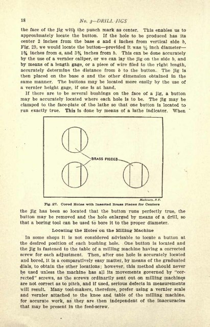
Fig. 27. Cored Holes with Inserted Brass Pieces for Centers<br />
the jig has been so located that the button runs perfectly true, the<br />
button may be removed and the hole enlarged by means <strong>of</strong> a drill, so<br />
that a boring tool can be used to bore it to the proper diameter.<br />
1<br />
Locating the Holes on the Milling- Machine<br />
In some shops it is not considered advisable to locate a button at<br />
the desired position <strong>of</strong> each bushing hole. One button is located and<br />
the jig is fastened to the table <strong>of</strong> a milling machine having a corrected<br />
screw for each adjustment. Then, after one hole is accurately located<br />
and bored, it is a comparatively easy matter, by means <strong>of</strong> the graduated<br />
dials, to obtain the other locations; however, this method should never<br />
be used unless the machine has all its movements governed by "cor-<br />
rected" screws, as the screws ordinarily sent out on milling machine t s<br />
are not correct as to pitch, and if used, serious defects in measurements<br />
will result. Many tool-makers, therefore, prefer using a vernier scale<br />
and vernier attached to the knee and table <strong>of</strong> the milling machine,<br />
for accurate work, as they are then independent <strong>of</strong> the inaccuracies<br />
that may be present in the feed-screw.