Drill Jigs Principles of Design Machinery ... - Evenfall Studios
Drill Jigs Principles of Design Machinery ... - Evenfall Studios
Drill Jigs Principles of Design Machinery ... - Evenfall Studios

Create successful ePaper yourself
Turn your PDF publications into a flip-book with our unique Google optimized e-Paper software.
30 No. j DRILL JIGS<br />
to one side about the hand screw G. When the collar has been put in<br />
place the clan?p is swung back, and in doing so, its motion is limited<br />
by the pin F, which brings it to a stop directly over the collar. At<br />
the top <strong>of</strong> the jig is a bushing B through which the drill is guided.<br />
When the outside diameter <strong>of</strong> the collars is likely to vary, the pins<br />
/), D, D, may be replaced by a central pin, L, as shown in the separate<br />
view in the cut, and the collar held on this while it is being drilled.*<br />
The jig shown in Fig. 43 is designed for drilling the holes in the<br />
center <strong>of</strong> collars, and the method <strong>of</strong> drilling, described below, also sug-<br />
gests the value <strong>of</strong> systematizing the work in using jigs. The collars<br />
to be drilled are made <strong>of</strong> annealed tool steel in sizes varying in thick-<br />
ness as well as in diameter and size <strong>of</strong> hole, and are cut <strong>of</strong>f from the<br />
t? Industrial<br />
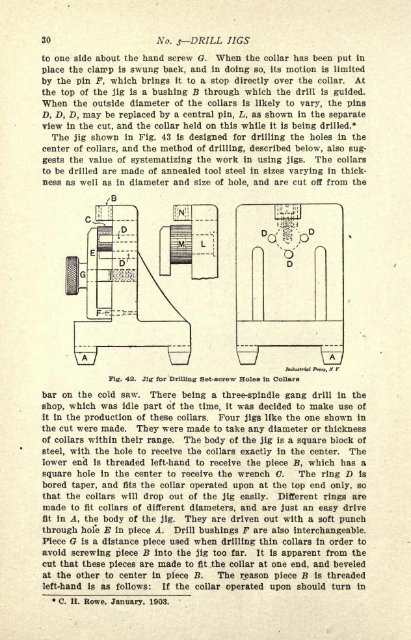
Fig. 42. Jig for <strong>Drill</strong>ing Set-screw Holes in Collars<br />
Prttf, ft. Y<br />
bar on the cold saw. There being a three-spindle gang drill in the<br />
shop, which was idle part <strong>of</strong> the time, it was decided to make use <strong>of</strong><br />
it in the production <strong>of</strong> these collars. Four jigs like the one shown in<br />
the cut were made. They were made to take any diameter or thickness<br />
<strong>of</strong> collars within their range. The body <strong>of</strong> the jig is a square block <strong>of</strong><br />
steel, with the hole to receive the collars exactly in the center. The<br />
lower end is threaded left-hand to receive the piece B, which has a<br />
square hole in the center to receive the wrench C. The ring D Is<br />
bored taper, and fits the collar operated upon at the top end only, so<br />
that the collars will drop out <strong>of</strong> the jig easily. Different rings are<br />
made to fit collars <strong>of</strong> different diameters, and are just an easy drive<br />
fit in A, the body <strong>of</strong> the jig. They are driven out with a s<strong>of</strong>t punch<br />
through hole E in piece A. <strong>Drill</strong> bushings F are also interchangeable.<br />
Piece G is a distance piece used when drilling thin collars in order to<br />
avoid screwing piece B into the jig too far. It is apparent from the<br />
cut that these pieces are made to fit the collar at one end, and beveled<br />
at the other to center in piece B. The reason piece B is threaded<br />
left-hand is as follows: If the collar operated upon should turn in<br />
C. H. Rowe, January, 1903.