Fluid mechanics of fibre suspensions related to papermaking - DiVA
Fluid mechanics of fibre suspensions related to papermaking - DiVA
Fluid mechanics of fibre suspensions related to papermaking - DiVA

Create successful ePaper yourself
Turn your PDF publications into a flip-book with our unique Google optimized e-Paper software.
<strong>Fluid</strong> <strong>mechanics</strong> <strong>of</strong> <strong>fibre</strong> <strong>suspensions</strong><br />
<strong>related</strong> <strong>to</strong> <strong>papermaking</strong><br />
RICHARD HOLM<br />
Doc<strong>to</strong>ral Thesis<br />
S<strong>to</strong>ckholm, Sweden 2005
<strong>Fluid</strong> <strong>mechanics</strong> <strong>of</strong> <strong>fibre</strong> <strong>suspensions</strong><br />
<strong>related</strong> <strong>to</strong> <strong>papermaking</strong><br />
by<br />
Richard Holm<br />
December 2004<br />
Doc<strong>to</strong>ral Thesis from<br />
Royal Institute <strong>of</strong> Technology (KTH)<br />
KTH Mechanics<br />
SE-100 44 S<strong>to</strong>ckholm, Sweden
Typsatt i AMS-L ATEX in MechThesis style.<br />
Akademisk avhandling som med tillst˚and av Kungliga Tekniska Högskolan i<br />
S<strong>to</strong>ckholm framlägges till <strong>of</strong>fentlig granskning för avläggande av teknologie<br />
dok<strong>to</strong>rsexamen fredagen den 14:e januari 2005 kl 10.00 i Kollegiesalen, Administrationsbygnaden,<br />
Kungliga Tekniska Högskolan, S<strong>to</strong>ckholm.<br />
c○Richard Holm 2004<br />
Edita AB, S<strong>to</strong>ckholm 2004
<strong>Fluid</strong> <strong>mechanics</strong> <strong>of</strong> <strong>fibre</strong> <strong>suspensions</strong> <strong>related</strong> <strong>to</strong> <strong>papermaking</strong><br />
Richard Holm 2004, KTH Mechanics, Royal Institute <strong>of</strong> Technology<br />
SE-100 44 S<strong>to</strong>ckholm, Sweden.<br />
Abstract<br />
This thesis deals with fluid dynamic mechanisms <strong>related</strong> <strong>to</strong> <strong>papermaking</strong>, specifically:<br />
the initial dewatering mechanisms during roll-forming and <strong>fibre</strong> motion<br />
in sedimentation and in shear flow.<br />
Pressure and wire position measurements have been conducted in a model<br />
resembling the forming zone and the measured pressure distributions are shown<br />
<strong>to</strong> have more complex patterns than the simple model p = T/R (where T is<br />
the wire tension and R is the roll radius). It is shown that an increase in wire<br />
tension has a similar effect as a decrease in flow-rate on the shape <strong>of</strong> the pressure<br />
distribution. In addition, it is shown that the drainage has a stabilizing effect<br />
on the dewatering pressure.<br />
The flow around the forming roll has also been modelled with the assumption<br />
that the wire is impermeable. A non-linear equation for the position <strong>of</strong><br />
the wire is derived that clearly shows that the Weber number, W e, is an important<br />
parameter. The equation is linearized around the trivial solution and<br />
has a standing wave solution with a specific wavelength that scales with the<br />
W e-number.<br />
Motion <strong>of</strong> non-Brownian <strong>fibre</strong> settling in a New<strong>to</strong>nian fluid at a small<br />
but finite Reynolds number has been studied experimentally. Two different<br />
regimes <strong>of</strong> sedimentation were identified. For dilute <strong>suspensions</strong>, <strong>fibre</strong>s generally<br />
fall without flipping and may travel at velocities larger than that <strong>of</strong> an<br />
isolated particle. In the semi-dilute regime we found the settling process <strong>to</strong> be<br />
dominated by large-scale fluctuations. The velocity fluctuations scale with the<br />
suspension volume concentration φ according <strong>to</strong> φ 1/3 , which is similar <strong>to</strong> the<br />
findings for settling spheres.<br />
The influence <strong>of</strong> shear on <strong>fibre</strong> orientation in the near wall region was<br />
studied in cellulose acetate <strong>fibre</strong> <strong>suspensions</strong>. At low concentration and low<br />
aspect ratio <strong>fibre</strong>s were observed <strong>to</strong> orient perpendicular <strong>to</strong> the streamwise<br />
direction (named rollers) in the near wall region whereas the orientation further<br />
in<strong>to</strong> the suspension was unchanged. As the concentration and aspect ratio<br />
increased the fraction <strong>of</strong> rollers decreased.<br />
Finally, an evaluation <strong>of</strong> a commercial Ultra Velocity Pr<strong>of</strong>iler unit in <strong>fibre</strong><br />
<strong>suspensions</strong> are presented. The idea was <strong>to</strong> determine the velocity and<br />
characterise the turbulence from ultra sound echoes from particles in the fluid.<br />
However, the spatial and/or temporal resolution <strong>of</strong> the measurements did not<br />
permit turbulence characterisation. These limitations might be possible <strong>to</strong><br />
overcome and some procedures are proposed and evaluated.<br />
Descrip<strong>to</strong>rs: applied fluid <strong>mechanics</strong>, <strong>fibre</strong> <strong>suspensions</strong>, roll-forming, sedimentation,<br />
shear flow, ultrasound measurements, <strong>papermaking</strong>
Preface<br />
<strong>Fluid</strong> <strong>mechanics</strong> is a basic science as well as an engineering subject, with applications<br />
in many different fields, such as aeronautics, energy conversion, geophysics,<br />
biomedical flows, chemical engineering, paper technology etc. <strong>Fluid</strong><br />
<strong>mechanics</strong> plays a fundamental role in some <strong>of</strong> these applications (for example<br />
aircraft engineering) and is an important fac<strong>to</strong>r in others. The application <strong>of</strong><br />
fluid <strong>mechanics</strong> <strong>to</strong> industrial processes has expanded in the recent years.<br />
The present work deals with some <strong>of</strong> the fluid dynamics mechanisms involved<br />
in <strong>papermaking</strong>. It is divided in<strong>to</strong> two parts: the initial part, treating<br />
dewatering mechanisms during roll forming, and a second part dealing with<br />
studies <strong>of</strong> <strong>fibre</strong> motion. The work is mainly experimental, using a model <strong>of</strong><br />
the roll forming section <strong>of</strong> a paper machine and studying the <strong>fibre</strong> motion in<br />
well-defined flow fields (sedimentation and shear flow). The study <strong>of</strong> mechanisms<br />
<strong>related</strong> <strong>to</strong> <strong>papermaking</strong> is challenging regarding both theoretical and<br />
experimental aspects. For example, <strong>fibre</strong> <strong>suspensions</strong> are opaque already at<br />
small volume concentrations <strong>of</strong> <strong>fibre</strong>s. To conduct measurements requires for<br />
example index-<strong>of</strong>-refraction matching or using ultrasonic techniques.<br />
The thesis contains two sections, a summary section and a paper section.<br />
In the summary, a brief description is given <strong>of</strong> <strong>papermaking</strong>, some relevant<br />
basic fluid <strong>mechanics</strong> and aspects regarding <strong>fibre</strong> <strong>suspensions</strong>. This is followed<br />
by the corresponding papers, that have been reset in the thesis format. Also<br />
the figures are adjusted <strong>to</strong> the format <strong>of</strong> thesis.<br />
S<strong>to</strong>ckholm, December 2004 Richard Holm
vi PREFACE
”The price <strong>of</strong> reliability is the pursuit <strong>of</strong> the utmost simplicity.<br />
It is a price which the very rich find the most hard <strong>to</strong> pay.”<br />
Sir An<strong>to</strong>ny Hoare, 1980
Contents<br />
Preface v<br />
Chapter 1. Papermaking 1<br />
1.1. The sheet forming process 3<br />
Chapter 2. <strong>Fluid</strong> <strong>mechanics</strong> 7<br />
2.1. Two-phase flow 11<br />
Chapter 3. <strong>Fluid</strong> <strong>mechanics</strong> <strong>of</strong> <strong>fibre</strong> suspension flows 15<br />
3.1. The behaviour <strong>of</strong> single <strong>fibre</strong>s in shear flows 15<br />
3.2. Influence <strong>of</strong> <strong>fibre</strong>s at low concentration 17<br />
3.3. Non-dilute <strong>fibre</strong> <strong>suspensions</strong> 18<br />
3.4. Pulp <strong>suspensions</strong> 20<br />
Chapter 4. Summary <strong>of</strong> the papers 25<br />
Paper 1 25<br />
Paper 2 25<br />
Paper 3 28<br />
Paper 4 28<br />
Paper 5 29<br />
Chapter 5. Papers and authors contributions 33<br />
Appendix A. Single-sided roll forming 35<br />
Bibliography 38<br />
Acknowledgements 42<br />
Papers<br />
Paper 1. Experimental studies on partial dewatering during<br />
roll forming <strong>of</strong> paper 45<br />
ix
x CONTENTS<br />
Paper 2. A theoretical analysis <strong>of</strong> the flow stability in roll<br />
forming <strong>of</strong> paper 65<br />
Paper 3. Visualization <strong>of</strong> Streaming-Like Structures During<br />
Settling <strong>of</strong> Dilute and Semi-Dilute Rigid Fibre<br />
Suspensions 81<br />
Paper 4. Influence <strong>of</strong> shear on <strong>fibre</strong> orientation in the near wall<br />
region 93<br />
Paper 5. A critical evaluation <strong>of</strong> ultrasound velocity pr<strong>of</strong>iling<br />
aiming <strong>to</strong>wards measurements in <strong>fibre</strong> <strong>suspensions</strong><br />
117
CHAPTER 1<br />
Papermaking<br />
The art <strong>of</strong> <strong>papermaking</strong> originated in China, and has been going on for more<br />
than 2000 years. Until the end <strong>of</strong> the 18 th Century, paper was made by hand,<br />
one sheet at a time. Today, a modern <strong>papermaking</strong> machine can produce up<br />
<strong>to</strong> 600,000 <strong>to</strong>ns <strong>of</strong> paper per year. The basic steps that have <strong>to</strong> be taken are<br />
however similar, as prescribed in a typical handcraft book<br />
• Take some <strong>of</strong> your slurry and fill with tap water until you have the proper<br />
consistency in the container.<br />
• Agitate the mixture in the mould with and up-and-down action rather<br />
that a swirling action.<br />
• Submerge a mould in<strong>to</strong> the suspension and lift up the mould and level<br />
<strong>of</strong>f, gently shake the mould <strong>to</strong> distribute pulp evenly.<br />
• Place the pulp and frame in another sink <strong>to</strong> allow the water <strong>to</strong> drain.<br />
• Carefully lift <strong>of</strong>f the <strong>to</strong>p wooden frame taking care not <strong>to</strong> disturb the<br />
pulp.<br />
• Place a blotting-paper on the pulp layer.<br />
• Use a rolling pin <strong>to</strong> get even more moisture out <strong>of</strong> the pulp.<br />
• Iron the paper pulp dry. Remove the blotting-paper carefully.<br />
• If the paper curls you may need <strong>to</strong> lay it flat under a heavy book for a<br />
few days until thoroughly cured<br />
From these instructions, it is obvious that <strong>papermaking</strong> is strongly coupled <strong>to</strong><br />
fluid <strong>mechanics</strong>: it is a <strong>fibre</strong> suspension flow (non-New<strong>to</strong>nian and dependent<br />
on the pulping process); turbulent mixing e.g. for obtaining a homogenous suspension;<br />
the sheet forming process (building up a sheet <strong>of</strong> paper); application<br />
<strong>of</strong> shear flows (shaking) <strong>to</strong> control the orientation and distribution <strong>of</strong> the <strong>fibre</strong>s;<br />
pressing and drying, which includes mechanical and thermodynamic processes.<br />
The distribution <strong>of</strong> <strong>fibre</strong>s, fillers and fines in the final paper sheet is quantified<br />
as paper formation, i.e. as the degree <strong>of</strong> local basis weight variation. This<br />
is one <strong>of</strong> the most important quality aspects <strong>of</strong> the final product.<br />
Machines used in modern paper production always consist <strong>of</strong> the forming<br />
section (see Figure 1.1), the press section and a drying section. Depending<br />
on the paper (or board) product manufactured other unit processes, such as<br />
e.g. coating, can be added but these three are always present. As already<br />
mentioned, the basic principles used in making traditional handsheet paper<br />
1
2 1. PAPERMAKING<br />
are still applied in modern <strong>papermaking</strong> machines. The modern process starts<br />
with a <strong>fibre</strong> suspension, at low concentration 1 <strong>of</strong> cellulose <strong>fibre</strong>s in water. The<br />
concentration is typically between 0.5-1% and the suspension is distributed<br />
by a nozzle in what is referred <strong>to</strong> as the headbox in a form <strong>of</strong> a plane liquid<br />
jet, on<strong>to</strong> either one or between two permeable bands called wires or forming<br />
fabrics. These move at approximately the same speed as the <strong>fibre</strong> suspension jet<br />
coming from the headbox. Initial dewatering (removal <strong>of</strong> water) is performed<br />
by allowing the water <strong>to</strong> pass through the holes in the forming fabrics while<br />
trapping the <strong>fibre</strong>s. Various methods can be used <strong>to</strong> influence sheet structure<br />
and increase dewatering capacity. After initial dewatering <strong>of</strong> the web, the solids<br />
content in the formed web is usually in the region <strong>of</strong> 12-15%, meaning that ≈<br />
95% <strong>of</strong> the water has been removed. The headbox and initial dewatering stage<br />
is usually referred <strong>to</strong> as the paper sheet forming process, or forming for short.<br />
Figure 1.1. The roll-blade Du<strong>of</strong>ormer CFD forming unit by Voith.<br />
After forming, the wet web passes through the press section, where further<br />
dewatering is performed via mechanical compression in a press nip. This is<br />
usually referred <strong>to</strong> as wet pressing and there are several technical approaches<br />
available, though the simplest way is <strong>to</strong> let the sheet pass between two counterrotating<br />
rolls. The paper sheet is supported by a press-felt as it passes through<br />
the nip. The felt also absorbs the water that is mechanically expelled from<br />
the wet sheet. The last stage in the manufacturing <strong>of</strong> paper is <strong>to</strong> remove the<br />
residual water by applying heat, i.e. drying. The drying unit is the largest<br />
part <strong>of</strong> a typical <strong>papermaking</strong> machine.<br />
The <strong>papermaking</strong> process requires large volumes <strong>of</strong> water, and is considerably<br />
energy intensive. Modern paper mills however use extensive recirculation<br />
<strong>of</strong> water <strong>to</strong> meet their environmental impact reduction obligations. Nowadays,<br />
1 Often the word consistency is used but concentration is more accurate.
1.1. THE SHEET FORMING PROCESS 3<br />
there are paper mills that use as little as 3 m 3 <strong>of</strong> water per <strong>to</strong>n <strong>of</strong> paper produced,<br />
compared <strong>to</strong> more than 100 m 3 per <strong>to</strong>n in days gone by.<br />
1.1. The sheet forming process<br />
The heart <strong>of</strong> the <strong>papermaking</strong> process is the headbox. The modern headbox<br />
typically consists <strong>of</strong> three parts: the flow distribu<strong>to</strong>r or manifold, the tube<br />
bank and the nozzle (see Figure 1.2). The <strong>fibre</strong> suspension is usually fed <strong>to</strong> the<br />
headbox from a perpendicular direction <strong>of</strong> the nozzle and jet. Usually the flow<br />
distribu<strong>to</strong>r has a tapered geometry designed <strong>to</strong> give a constant static pressure<br />
across the machine width. This will ensure that the speed <strong>of</strong> the headbox jet<br />
is constant along the width <strong>of</strong> the paper machine.<br />
A-A<br />
B-B<br />
C-C<br />
Wire 1<br />
A A<br />
B B<br />
C C<br />
Wire 2<br />
Figure 1.2. The Valmet SymFlow HS headbox and the different<br />
parts. The cross-sectional view <strong>to</strong> the left, illustrate the<br />
different parts in the headbox.<br />
On exiting the manifold, the <strong>fibre</strong> suspension enters the tube bank through<br />
a system <strong>of</strong> holes, usually representing around 10% <strong>of</strong> the area. The main<br />
purpose <strong>of</strong> the tube bank is <strong>to</strong> produce a pressure drop for promoting a more<br />
uniform flow pr<strong>of</strong>ile across the full width <strong>of</strong> the <strong>papermaking</strong> machine. Each<br />
flow channel in the tube banks <strong>of</strong> modern headboxes features a step-diffuser<br />
design, see e.g. Hyensjö et al. (2004), which results in a defined separation<br />
(and turbulence) <strong>of</strong> the flow, which provides a controlled and elevated pressure<br />
drop. The turbulence generated was earlier believed <strong>to</strong> play an important role<br />
in improving the formation in the final paper sheet.
4 1. PAPERMAKING<br />
On exiting the tube bank, the suspension flow enters the headbox nozzle<br />
accelerating the flow and producing a free plane jet. The flow in the contraction<br />
<strong>of</strong> a headbox has been subject <strong>to</strong> extensive research, both experimentally<br />
(Chuang (1982), Shands (1991), Farring<strong>to</strong>n (1991) and Parsheh (2001)) and<br />
numerically (Hua & et. al (1999) and Bandhakavi & Aidun (1999)). Most <strong>of</strong><br />
these studies have looked at the behaviour <strong>of</strong> a New<strong>to</strong>nian fluids, such as water<br />
or air in a headbox contraction. Parsheh (2001) performed measurements and<br />
modelled the effect <strong>of</strong> contraction on turbulence, and concluded that only the<br />
most advanced turbulence models can be used <strong>to</strong> predict flow in headbox contractions,<br />
assuming that the effect <strong>of</strong> the <strong>fibre</strong>s in the suspension is neglected.<br />
Ideally, when the <strong>fibre</strong> suspension exits the headbox nozzle it is in the form<br />
<strong>of</strong> a two-dimensional plane jet, typically 10 mm thick and up <strong>to</strong> 10 m wide.<br />
This jet impinges on the wire at a narrow angle and at a distance <strong>of</strong> 10-20 cm<br />
downstream the headbox nozzle outlet (<strong>of</strong>ten referred <strong>to</strong> as the headbox slice).<br />
The hydrodynamics <strong>of</strong> the plane jet has been thoroughly studied by Söderberg<br />
(1999), who determined the stability <strong>of</strong> a plane jet experimentally and theoretically,<br />
and showed that the jet was susceptible <strong>to</strong> two-dimensional wave disturbances.<br />
Söderberg was able <strong>to</strong> observe the breakdown <strong>of</strong> the waves, which<br />
may result in longitudinal (streaky) structures in the jet. Streaky structures<br />
can also be seen in the final paper sheets. Söderberg suggested that the streaks<br />
in the paper were due <strong>to</strong> the streaks observed inside the jet.<br />
At impingement the jet speed is close <strong>to</strong> the wire speed, though a difference<br />
may be set intentionally in a real paper machine–either a rush (jet speed greater<br />
than wire speed) or a drag (wire speed greater than jet speed)–in order <strong>to</strong><br />
influence sheet structure and properties. The interaction between the <strong>fibre</strong><br />
suspension jet and the wires has a clear influence on the surface structure <strong>of</strong><br />
the paper sheet.<br />
The design <strong>of</strong> the forming section (or former) <strong>of</strong> <strong>papermaking</strong> machines<br />
can vary. In its simplest form–as used in the earliest <strong>papermaking</strong> machines–<br />
dewatering is a result <strong>of</strong> gravity. This is usually referred <strong>to</strong> as fourdrinier<br />
forming, after the Fourdrinier brothers Henry and Sealy, who designed the first<br />
<strong>papermaking</strong> machine. Here the jet lands on one horizontal wire, supported<br />
from below on what is called the forming table. An early development <strong>of</strong> this<br />
was the introduction <strong>of</strong> forced dewatering using local suction below the wire,<br />
as well as generating additional activity (pulsations and shear) on the forming<br />
table using foils (deflec<strong>to</strong>r blades), or even by horizontally shaking the forming<br />
table mechanically.<br />
In contrast <strong>to</strong> single wire forming, twin-wire forming (also called gapforming)<br />
involves the <strong>fibre</strong> suspension being enclosed between two wires in a<br />
sandwich-like design. This symmetrical, wire-suspension-wire sandwich results<br />
in a quadrupling <strong>of</strong> the dewatering capacity compared with single wire forming.<br />
Twin-wire forming also has the potential <strong>to</strong> produce a more symmetric sheet.<br />
If the wire-suspension-wire sandwich is deflected mechanically the wire tension<br />
produces an increase in the pressure between the wires, thus enhancing
1.1. THE SHEET FORMING PROCESS 5<br />
dewatering. This can be achieved by pressing a “forming” roll or deflec<strong>to</strong>r<br />
blades against the wire-sheet-wire sandwich from one side (see Norman (1989),<br />
this is called roll forming or blade-forming respectively. Additionally, the localised<br />
pressure pulses created by the blades in blade forming have a significant<br />
influence on the sheet structure. If used properly, they can break-up <strong>fibre</strong> flocs<br />
and improve paper formation. In principle, pressure pulses always have a detrimental<br />
effect on the strength <strong>of</strong> the sheet.<br />
These days there are pure fourdrinier forming units, hybrid forming units<br />
(combinations <strong>of</strong> fourdrinier and twin-wire forming units), and twin-wire forming<br />
units in use, with the majority <strong>of</strong> these being fourdrinier or hybrid units.<br />
The most modern paper machines use a combination <strong>of</strong> roll forming followed<br />
by blade forming and the cost for obtaining one <strong>of</strong> these (paper machine only)<br />
is in the range <strong>of</strong> 2,000,000 Euro ($2,600,000) depending on paper grade.<br />
Recently a numerical model <strong>of</strong> the forming section was presented by Turnbull<br />
et al. (1997), which was improved with a two-dimensional approach by<br />
Chen et al. (1998). A similar model was presented by Zahrai (1997) that could<br />
estimate the pressure and wire position in both roll and blade forming and her<br />
result showed a possibility <strong>of</strong> a standing wave solution. Blade forming was also<br />
the subject in the numerical work presented by Holmqvist (2002), aimed at the<br />
interference between pressure pulses originating from a series <strong>of</strong> blades. A numerical<br />
study by Dalpke (2002), looking at the initial impingement zone in roll<br />
forming, showed agreement with experimental data by Gooding et al. (2001).<br />
For an overview <strong>of</strong> the area see Malashenko & Karlsson (2000), and also the<br />
extensive review by Norman & Söderberg (2001), covering recent developments<br />
in paper forming. Some very recent studies <strong>of</strong> floc behaviour in the forming<br />
zone have been presented by Bergström (2003) and ˚Akesson (2004).
6 1. PAPERMAKING
CHAPTER 2<br />
<strong>Fluid</strong> <strong>mechanics</strong><br />
In general, the motion <strong>of</strong> a New<strong>to</strong>nian fluid such as water or air, is given by<br />
Navier-S<strong>to</strong>kes equations. Together these equations constitute one scalar and<br />
one vec<strong>to</strong>r equation; resulting in four coupled, partial differential equations<br />
for pressure (which is a scalar variable), and velocity (which is a vec<strong>to</strong>r variable<br />
with three components). However these coupled equations are non-linear,<br />
which means that the system is mathematically difficult <strong>to</strong> solve. Though analytical<br />
solutions do exist for a number <strong>of</strong> generic cases, they mostly have <strong>to</strong><br />
be solved numerically. Because <strong>of</strong> this, physical observations from experiments<br />
or nature still play an important part in fluid <strong>mechanics</strong>. The Navier-S<strong>to</strong>kes<br />
equations are represented as follows<br />
∂u<br />
∂t<br />
1<br />
+ u · ∇u = −<br />
ρ ∇p + ν∇2u + 1<br />
F, (2.1)<br />
ρ<br />
where u = uex + vey + wez is the velocity vec<strong>to</strong>r with its three components<br />
(u, v, w) and p is the pressure. The parameters are ν = µ/ρ, which is the<br />
kinematic viscosity, where µ is the dynamic pressure and ρ the density. The<br />
last term F represents a volumetric force (for example gravity), which can be<br />
neglected in some problems (F = 0). The terms on the left-hand side <strong>of</strong> the<br />
equation is due <strong>to</strong> the acceleration <strong>of</strong> the fluid, also referred <strong>to</strong> as inertia terms,<br />
whereas on the right-hand side <strong>of</strong> the equation the first term is the pressure<br />
gradient (force), and the second term represents viscous forces. The continuity<br />
equation is expressed as<br />
∂ρ<br />
+ ∇ · ρu = 0. (2.2)<br />
∂t<br />
When this system <strong>of</strong> equations is <strong>to</strong> be solved, initial and boundary conditions<br />
are needed. A boundary condition occurring frequently is a rigid, impermeable,<br />
or solid wall. This condition implies that no fluid is able <strong>to</strong> pass<br />
through the wall, and consequently the wall normal velocity is zero. Additionally,<br />
the two other components (parallel <strong>to</strong> the wall) are also zero. This<br />
boundary condition is usually referred <strong>to</strong> as a no-slip condition. There are other<br />
types <strong>of</strong> boundaries such as free surfaces and permeable walls with constant<br />
or variable permeability. Each <strong>of</strong> these has <strong>to</strong> be treated appropriately when<br />
solving the equations.<br />
7
8 2. FLUID MECHANICS<br />
Frequently some simplifications are introduced <strong>to</strong> facilitate solving these<br />
equations. In Equations 2.1 and 2.2, the fluid density (ρ) is assumed <strong>to</strong> be constant.<br />
The flow is then said <strong>to</strong> be incompressible–a simplification <strong>of</strong>ten made in<br />
regard <strong>to</strong> liquids. If both pressure and velocity are constant in time, this is referred<br />
<strong>to</strong> as a steady state condition. Furthermore, nature is three-dimensional,<br />
but in some flow cases, reducing the problem <strong>to</strong> one or two dimensions can be<br />
justified, further simplifying the equations.<br />
A useful concept when studying fluid flows is that <strong>of</strong> the dynamic similarities.<br />
A flow that at first appeared different but under same circumstances<br />
exhibit the same pattern is called dynamically similar. This can be revealed<br />
if the variables in the equations are scaled in an appropriate way. This <strong>of</strong>ten<br />
result in non-dimensional groups and the most famous example is the Reynolds<br />
number (Re), expressing the ratio between inertia and viscous forces for<br />
New<strong>to</strong>nian fluids.The Reynolds number is defined as<br />
Re = ρUL<br />
µ , (2.3)<br />
where U and L are the characteristic velocity and length scales respectively.<br />
The Reynolds number can be derived by scaling the Navier-S<strong>to</strong>kes equations,<br />
resulting in<br />
∂u<br />
∂t<br />
1<br />
+ u · ∇u = −∇p +<br />
Re ∇2u + 1<br />
F. (2.4)<br />
F r<br />
Another non-dimensional number appears in Equation 2.4, namely the<br />
Froude number (F r), which represents the ratio <strong>of</strong> inertial <strong>to</strong> volumetric forces.<br />
This is for example relevant in bouyancy driven flows, and defined as<br />
U<br />
F r = , (2.5)<br />
(gL) 1/2<br />
where g is the gravitational acceleration. Another non-dimensional number is<br />
the Weber number (W e), which is useful for characterising fluid flow where<br />
there is an interface between two immiscible fluids, for example water and air.<br />
The Weber number is defined as<br />
W e = ρU 2L , (2.6)<br />
T<br />
where T is the surface tension.<br />
The Péclet number (P e) express the relationship between the transport<br />
<strong>of</strong> material (convection) by the fluid and the diffusivity. Diffusivity can be <strong>of</strong><br />
different physical origin, such as thermal or rotary diffusivity, and in the latter<br />
case is seen as random (or Brownian) motion. This flexibility has advantages<br />
in characterising the flow motion under influence <strong>of</strong> different mechanisms in<br />
the flow. The following definition <strong>of</strong> the Péclet number has been provided by<br />
for example Petrie (1999), regarding particles suspended in a fluid, as<br />
P e = G<br />
, (2.7)<br />
Dr
2. FLUID MECHANICS 9<br />
where G is rate <strong>of</strong> strain and Dr is the rotary diffusivity that can be expressed<br />
as the Brownian diffusion coefficient according <strong>to</strong><br />
Dr = kBTa<br />
, (2.8)<br />
ζr<br />
where ζr is the rotational friction constant, kB Boltzmann’s constant and Ta<br />
absolute temperature.<br />
Looking in more detail at the Reynolds number, viscous forces dominate<br />
when Re ≪ 1. This leads <strong>to</strong> a simplification <strong>of</strong> the Navier-S<strong>to</strong>kes equations,<br />
where at every point in the fluid, a balance between the local pressure and the<br />
viscous forces has <strong>to</strong> be achieved. In the limit Re → 0, the inertial forces are so<br />
small that they can be neglected, and the resulting equations are linear. This<br />
flow regime is known as creeping flow. There are two interesting features worth<br />
mentioning here regarding <strong>to</strong> creeping flow:<br />
• The flow is reversible, see for example the flow around a sphere by<br />
Schlichting (1999).<br />
• Long-range interactions, are possible for example when particles influence<br />
each other over distances larger than their size. This is observed<br />
among settling spheres.<br />
New<strong>to</strong>nian fluid flow can be <strong>of</strong> two distinct types–laminar or turbulent.<br />
Laminar flow is characterised by a deterministic flow-field, which can be time<br />
dependent. Due <strong>to</strong> the physics, a laminar flow can become unstable resulting<br />
in a turbulent flow. This behaviour can also be deduced from the non-linearity<br />
<strong>of</strong> the equations, where the Reynolds number is the controlling parameter. For<br />
low Reynolds numbers, laminar flows can exist but as Re increases most flows<br />
undergo transition <strong>to</strong> turbulent flow.<br />
The following brief summary <strong>of</strong> the phenomenon <strong>of</strong> turbulence has been<br />
provided by Trit<strong>to</strong>n (1988): “each time a flow changes as a result <strong>of</strong> an instability,<br />
one’s ability <strong>to</strong> predict the details <strong>of</strong> the motion is reduced. When<br />
successive instabilities have reduced the level <strong>of</strong> predictability so much that it<br />
is appropriate <strong>to</strong> describe a flow statistically, rather than in every detail, then<br />
one says that the flow is turbulent”<br />
Turbulence or turbulent flow, involves a wide range <strong>of</strong> scales and Kolmogorov<br />
(see Pope (2000)) presented a theory for turbulence, based on a number<br />
<strong>of</strong> hypotheses, taking in<strong>to</strong> consideration the energy production range (PR),<br />
the inertial range (IR), and the dissipative range (DR) <strong>of</strong> scales, see Figure 2.1.<br />
These hypotheses states that high-Reynolds-number turbulence can be seen as<br />
locally homogenous and isotropic if energy is constantly fed in<strong>to</strong> the system and<br />
that the turbulent velocity field can be seen as eddies <strong>of</strong> different sizes. The<br />
large eddies in (PR) becomes smaller and smaller until the smallest eddies dissipate<br />
in (DR). The energy cascades from large eddies <strong>to</strong> small eddies through<br />
the intermediate region and there is no energy build up at any scales. So the<br />
intermediate eddies can be characterised by their size and velocity, or length<br />
and time scale. Kolmogorov showed on dimensional grounds that these eddies
10 2. FLUID MECHANICS<br />
Figure 2.1. A schematic picture <strong>of</strong> the Kolmogorov energy<br />
cascade, from production range (P.R.), transfer in inertia range<br />
(I.R.) and finally dissipative range (DR), see e.g. Minier &<br />
Peirano (2001).<br />
must be expressed in term <strong>of</strong> the energy flux (< ɛ >) and the viscosity(ν). The<br />
length η and time scale τ can be shown <strong>to</strong> be<br />
η = ν3 1/4, ν 1/2. τ = (2.9)<br />
< ɛ ><br />
< ɛ ><br />
In order <strong>to</strong> obtain statistical quantities for the flow, the pressure and velocity<br />
are written as<br />
U(r) + u(r, t) and P(r) + p(r, t),<br />
where r = rxex + ryey + rzex is the spatial vec<strong>to</strong>r U(r) = Uex + V ey + W ez<br />
and P(r) represent mean quantities, and u(r, t) = uex + vey + wez and p(r, t)<br />
represent fluctuating quantities, which have a mean value that is identically<br />
zero. This decomposition is usually referred <strong>to</strong> as Reynolds decomposition and<br />
the resulting momentum equations are<br />
∂U<br />
∂t<br />
∂V<br />
∂t<br />
∂U ∂U ∂U<br />
+ U + V + W<br />
∂x ∂y ∂z =<br />
− ∂P<br />
2 ∂ U<br />
+ ν<br />
∂x ∂x2 + ∂2U ∂y2 + ∂2U ∂z2 <br />
∂u<br />
−<br />
2<br />
<br />
∂uv ∂uw<br />
+ +<br />
∂x ∂y ∂z<br />
∂V ∂V ∂V<br />
+ U + V + W<br />
∂x ∂y ∂z =<br />
− ∂P<br />
2 ∂ V<br />
+ ν<br />
∂y ∂x2 + ∂2V ∂y2 + ∂2V ∂z2 <br />
<br />
∂uv ∂v2 ∂vw<br />
− + +<br />
∂x ∂y ∂z<br />
(2.10)<br />
(2.11)
∂W<br />
∂t<br />
+ U ∂W<br />
∂x<br />
− ∂P<br />
∂z<br />
+ ν<br />
2.1. TWO-PHASE FLOW 11<br />
∂W ∂W<br />
+ V + W<br />
∂y ∂z =<br />
2 ∂ W<br />
∂x2 + ∂2W ∂y2 + ∂2W ∂z2 <br />
<br />
∂uw ∂vw ∂w2<br />
− + + . (2.12)<br />
∂x ∂y ∂z<br />
The continuity equation becomes<br />
∂U<br />
∂x<br />
+ ∂U<br />
∂y<br />
+ ∂U<br />
∂z<br />
= 0, (2.13)<br />
where bar f represents the time average <strong>of</strong> quantity f. The resulting Reynolds<br />
equations are similar <strong>to</strong> the Navier-S<strong>to</strong>kes equations, with one significant<br />
difference; there are velocity covariances (u 2 , uv and so on), known as the<br />
Reynolds stresses. For general three-dimensional flow, there are now four independent<br />
equations, being the three components <strong>of</strong> the Reynolds equation and<br />
the continuity equation. However, there are 4 + 9 = 13 unknowns. There is<br />
consequently a closure problem; commonly solved by replacing the Reynolds<br />
stress terms with model terms, such as in turbulence modelling.<br />
The simplest way <strong>to</strong> close the equations is <strong>to</strong> use the eddy viscosity hypothesis<br />
(see for example Pope (2000)) and assume that the turbulence is isotropic.<br />
Hence, all Reynolds stress components are identical and assumed <strong>to</strong> be given<br />
by a constant multiplied with the local mean shear. There are more complete<br />
and exact ways <strong>to</strong> model the Reynolds stress term. It is also possible <strong>to</strong><br />
solve the Navier-S<strong>to</strong>kes equations directly through direct numerical simulation<br />
(DNS) with no empirical closure models. These simulations resolve all turbulent<br />
scales and result in the time-dependent velocity at any point in the flow.<br />
However due <strong>to</strong> its high demand on computational resources, this approach is<br />
limited <strong>to</strong> low-Reynolds-number turbulence in simple geometries.<br />
2.1. Two-phase flow<br />
The effects <strong>of</strong> particles in a carrier phase–like spheres in a liquid–are similar <strong>to</strong><br />
the effects <strong>of</strong> a grid or screen in turbulent flow, where turbulence is generated<br />
or attenuated depending on the grid size and turbulence intensity. Given the<br />
particle size, concentration and the initial turbulence level, turbulence is either<br />
suppressed or enhanced in two-phase flow (see for example Minier & Peirano<br />
(2001) or the experimental study by Matas et al. (2003)).<br />
In general, small particles tend <strong>to</strong> suppress the turbulence level, whereas<br />
large particles seem <strong>to</strong> enhance it. This turbulence modulation can influence<br />
the carrier phase in several ways, for example leading <strong>to</strong>: displacement <strong>of</strong> the<br />
flow field by flow around the particles; generation <strong>of</strong> wakes behind the particles;<br />
modification <strong>of</strong> velocity pr<strong>of</strong>iles in the flow field and a corresponding change<br />
in turbulence generation; introduction <strong>of</strong> additional length scales that may<br />
influence the turbulence dissipation; transferral <strong>of</strong> turbulence energy <strong>to</strong> the<br />
motion <strong>of</strong> the dispersed phase or disturbance <strong>of</strong> flow due <strong>to</strong> particle-<strong>to</strong>-particle<br />
interactions.
12 2. FLUID MECHANICS<br />
As the particle generally do not follow the fluid ( referred <strong>to</strong> as the crossing<br />
trajec<strong>to</strong>ry effect, see for example Crowe et al. (1998)), their dispersion does not<br />
equal that <strong>of</strong> the fluid. To classify particle dispersion, the S<strong>to</strong>kes number (St)<br />
is used <strong>to</strong> assess the particle behaviour in relation <strong>to</strong> the instantaneous flow<br />
motion and defined as<br />
St = τpU<br />
, (2.14)<br />
L<br />
where τp is the time required for a particle <strong>to</strong> respond <strong>to</strong> a change in the fluid,<br />
which has characteristic velocity and length scales U and L respectively. If<br />
St ≪1, the response time <strong>of</strong> a particle is faster than the characteristic time<br />
<strong>of</strong> the flow field. Hence, the particle and the fluid velocities are in velocity<br />
equilibrium, i.e. the particle will follow the flow. If St ≫1, the particle will<br />
not respond <strong>to</strong> the fluid velocity changes, which results in a lag between the<br />
fluid velocity and particle velocity.<br />
It is also important <strong>to</strong> consider how the fluid behaves under deformation,<br />
which can be described by a constitutive equation. This equation describes<br />
the relation between the stress in the fluid and the rate <strong>of</strong> strain, and defines<br />
the rheology <strong>of</strong> the fluid. If the stress is linearly <strong>related</strong> <strong>to</strong> the rate <strong>of</strong> strain<br />
(a linear constitutive model), the fluid is classified as a New<strong>to</strong>nian fluid (as<br />
discussed above); in all other cases it is classified as non-New<strong>to</strong>nian. This is<br />
the case in many flows e.g. polymer flows. In two-phase flows, these may be<br />
non-New<strong>to</strong>nian, however this depends on several aspects and one is the volume<br />
concentration. For example if the volume concentration <strong>of</strong> particles in the fluid<br />
is moderate, a simplification <strong>of</strong> a New<strong>to</strong>nian fluid (for both phases), can be<br />
used under some circumstances as long as the continuum assumption is valid.<br />
Two-phase flows in which one phase is distributed in the other phase without<br />
mechanical connection, e.g. particles, are called disperse. Particle-fluid<br />
interactions are responsible for the exchange <strong>of</strong> quantities between the phases<br />
(also called coupling) for example the transfer <strong>of</strong> mass, momentum and energy<br />
between the phases. The included terms are highly specific <strong>to</strong> each flow case;<br />
for example dependent on phase character (gas, liquid or solid), chemical processes,<br />
combustion, and the degree <strong>of</strong> steadiness <strong>of</strong> the flow (for further reading<br />
see Crowe et al. (1998)). The coupling in two-phase flow is conceptually important<br />
here. If one phase affects the other phase with no reverse effect, this in<br />
known as one-way coupling. If there is a mutual effect between the phases, this<br />
is called two-way coupling. The latter would apply in a complete description<br />
<strong>of</strong> the two-phase flow, however the calculations present numerous challenges.<br />
Consequently, one-way coupling is most frequently used, see for example the<br />
two-phase calculations by Minier & Peirano (2001).<br />
If the focus is restricted <strong>to</strong> solids in liquids, then a dilute dispersed twophase<br />
flow is one in which the particle motion is controlled by fluid forces such<br />
as drag and lift. On the other hand, in a dense flow the particle motion is<br />
controlled by collisions which situation can be estimated either by considering<br />
the particle momentum response time and the time interval between collisions,
2.1. TWO-PHASE FLOW 13<br />
or as a mass coupling measure–the number <strong>of</strong> particles in a unit volume and<br />
the probability <strong>of</strong> collisions.<br />
The forces acting on the particle are subdivided in<strong>to</strong>: (a) body forces, such<br />
as gravity or electrostatic forces, and (b) surface forces, due <strong>to</strong> drag and lift<br />
forces, and result in a momentum coupling between the two phases. In general,<br />
the surface forces depend on particle shape and orientation, though also on the<br />
flow parameters such as the viscosity, Reynolds number, turbulence intensity<br />
etc. One fundamental example is S<strong>to</strong>kes flow around a non-rotating sphere<br />
falling in a liquid under the influence <strong>of</strong> gravity at low Reynolds number, for<br />
which the drag force varies linearly and inversely with Reynolds number.
14 2. FLUID MECHANICS
CHAPTER 3<br />
<strong>Fluid</strong> <strong>mechanics</strong> <strong>of</strong> <strong>fibre</strong> suspension flows<br />
Basic fluid <strong>mechanics</strong> can been used <strong>to</strong> theoretically model the motion and coupling<br />
between a liquid and suspended <strong>fibre</strong>s in order <strong>to</strong> get the bulk behaviour <strong>of</strong><br />
the <strong>fibre</strong> suspension. The three necessary steps have been summarised by Petrie<br />
(1999), being: (1) modelling the motion <strong>of</strong> an individual <strong>fibre</strong>, (2) modelling<br />
the evolution <strong>of</strong> the orientation distribution <strong>of</strong> many <strong>fibre</strong>s, and (3) estimating<br />
the contribution <strong>of</strong> <strong>fibre</strong>s <strong>to</strong> the bulk stress, in terms <strong>of</strong> bulk flow.<br />
Unlike spheres, the motion <strong>of</strong> a <strong>fibre</strong> depend on its orientation in the flow<br />
field, see for example Mackaplow & Shaqfeh (1998) who studied <strong>fibre</strong> motion<br />
during sedimentation. The <strong>fibre</strong> orientation is an important physical quantity<br />
and do not only refer <strong>to</strong> the rheology <strong>of</strong> <strong>fibre</strong> <strong>suspensions</strong>. This is seen in extrusion<br />
<strong>of</strong> <strong>fibre</strong>-reinforced composites and in <strong>papermaking</strong> where the mechanical<br />
properties are strongly linked <strong>to</strong> the <strong>fibre</strong> orientation. During these processes<br />
the understanding <strong>of</strong> the evolution <strong>of</strong> the <strong>fibre</strong> orientation distribution is also<br />
important. Hence, information regarding the transient and non-equilibrium<br />
effects are needed in order <strong>to</strong> understand <strong>fibre</strong> suspension behaviour.<br />
3.1. The behaviour <strong>of</strong> single <strong>fibre</strong>s in shear flows<br />
The hydrodynamics <strong>of</strong> a single particle in a shear flow was addressed by Jeffery<br />
(1922) and the motion <strong>of</strong> a single ellipsoid in a New<strong>to</strong>nian fluid is referred <strong>to</strong><br />
as a Jefferey orbit. Looking at an ellipsoid in a simple shear but neglecting the<br />
Brownian motion <strong>of</strong> the particle–that is the tendency for a particle <strong>to</strong> assume<br />
a random distribution–the important motion is its rotation. The inertial forces<br />
can be neglected as the particle’s Reynolds number is small (Re ≪ 1). Jeffery’s<br />
theory predicts a tumbling motion <strong>of</strong> a rod-like particle, which has also been<br />
confirmed experimentally. Some early experimental studies were conducted<br />
by Mason and co-workers (Trevelyan & Mason (1951) and Mason & Manley<br />
(1957)). Unlike spheres, the motion <strong>of</strong> the rod-like particle is described in an<br />
orbit, due <strong>to</strong> its initial orientation and independent in time. Consequently in<br />
a <strong>fibre</strong> suspension (no <strong>fibre</strong>-<strong>to</strong>-<strong>fibre</strong> collisions), the stress will vary periodically<br />
and never reach a steady-state condition. Jeffery’s theory gives coupled differential<br />
equations for the <strong>fibre</strong> orientation in the spherical coordinates (ϕ, θ) and<br />
their solution as<br />
tan ϕ = r tan ˙γt<br />
r + r −1 + k , tan θ =<br />
15<br />
Cr<br />
(r 2 cos 2 ϕ + sin 2 ϕ) 1/2<br />
(3.1)
16 3. FLUID MECHANICS OF FIBRE SUSPENSION FLOWS<br />
t 0<br />
z<br />
t 1<br />
y<br />
U(y)<br />
Figure 3.1. A simple shear flow and a single <strong>fibre</strong> under<br />
schematic rotation, where t0 < t1.<br />
x<br />
where r is the <strong>fibre</strong> aspect ratio (r = lp/d where lp is the particle length and d<br />
the diameter), ˙γ the shear rate and C and k are constants that depend on the<br />
initial orientation <strong>of</strong> the <strong>fibre</strong>.<br />
The time t is the local time in the orbit and the constant C, can take any<br />
positive values. With C=0 the <strong>fibre</strong> is aligned along the z-axis, see Figure 3.1,<br />
and with C→ ∞ the <strong>fibre</strong> is rotating in the xy-plane. Thus, in order <strong>to</strong> describe<br />
the periodic <strong>fibre</strong> flipping motion in a shear flow different terms like “direc<strong>to</strong>r<br />
tumbling”, “log-rolling” and “kayaking” have been used in the literature. The<br />
pathline given by the intersection <strong>of</strong> the axis <strong>of</strong> symmetry <strong>of</strong> the particle and<br />
a unit sphere is used <strong>to</strong> describe the <strong>fibre</strong> orientation, see Figure 3.2, where<br />
Jeffery orbits for different values <strong>of</strong> C can be seen. This theoretically obtained<br />
result has also been confirmed experimentally, see e.g. Trevelyan & Mason<br />
(1951). Single <strong>fibre</strong> motion was further explored by Hinch & Leal (1972). They<br />
included the effect <strong>of</strong> Brownian motion in their study, which was excluded by<br />
Jeffery.<br />
The time the <strong>fibre</strong> spends in the orbit depends on the shear rate and<br />
the aspect ratio. In general, very long, slender <strong>fibre</strong>s are aligned in the flow<br />
direction most <strong>of</strong> the time, and the time spent flipping is somewhere in the<br />
order <strong>of</strong> r −1 . For very slender particles, <strong>fibre</strong> aspect ratio r ≫ 1, the theory by<br />
Jeffrey can be simplified, which was presented for example by Burger (1938).<br />
The result <strong>of</strong> the simplified coupled differential equations are<br />
θ<br />
z<br />
y<br />
φ<br />
dθ ˙γ<br />
=<br />
dt 4 sin 2θ sin 2ϕ (3.2)<br />
dϕ<br />
dt = ˙γ cos2 ϕ. (3.3)<br />
Jefferys theory inspired both theoretical and experimental studies and a relation<br />
between the rate <strong>of</strong> rotation and the aspect ratio resulted in an introduction <strong>of</strong><br />
an effective aspect ratio. Brether<strong>to</strong>n (1962) extended the work by Jeffery and<br />
showed that any fore-and-aft symmetric particle rotates with the period<br />
tr = 2π <br />
re + re<br />
˙γ<br />
−1<br />
x<br />
(3.4)
3.2. INFLUENCE OF FIBRES AT LOW CONCENTRATION 17<br />
1<br />
0.8<br />
0.6<br />
0.4<br />
1<br />
0.8<br />
0.6<br />
z<br />
0.4<br />
0.2<br />
y 0<br />
0.2<br />
0.4<br />
0.6<br />
0.8<br />
1<br />
C=1<br />
C=0.5<br />
C=0.05<br />
0.4 0.3 0.2 0.1 0 0.1 0.2 0.3 0.4<br />
x<br />
Figure 3.2. The Jeffery orbit for different constants <strong>of</strong> C, the<br />
pathline <strong>of</strong> the <strong>fibre</strong> end.<br />
if an effective aspect ratio re is used.<br />
However, several studies has tried <strong>to</strong> determine a uniquely defined effective<br />
aspect ratio, but this has not been realized. The values depend on the aspect<br />
ratio regime and shape <strong>of</strong> the <strong>fibre</strong> ends. Experimentally Mason & Manley<br />
(1957) estimated that re = 0.7r for aspect ratios r ≈20. Generally, the effective<br />
aspect ratio tend <strong>to</strong> be less than the actual aspect ratio, which is a results <strong>of</strong><br />
that <strong>fibre</strong>s tend <strong>to</strong> rotate faster than predicted by theory.<br />
3.2. Influence <strong>of</strong> <strong>fibre</strong>s at low concentration<br />
Theoretical work by Cox (1970) resulted in a model <strong>of</strong> <strong>to</strong>rque and forces on a<br />
solid, long, slender body in a given undisturbed S<strong>to</strong>kes flow. In his slender body<br />
theory Cox included interaction (no collisions) between two or more slender<br />
bodies as well the effect <strong>of</strong> a wall. The force and <strong>to</strong>rque were derived for straight<br />
slender bodies as well as for curved slender bodies. Cox also derived a theory for<br />
the forces acting on flexible <strong>fibre</strong>s and incorporated buckling, which is observed<br />
for flexible bodies in shear flow. In addition, he proposed a modification for<br />
the case <strong>of</strong> small but finite particle Reynolds number. For this case, the inertia<br />
effects resulted in a modification <strong>to</strong> the orbit constant C, given by the theory by<br />
Jeffery. Cox applied the model on a shear flow and the result was a rheological<br />
behaviour <strong>of</strong> the suspension in an efficient viscosity.<br />
Contemporary <strong>to</strong> Cox’s work Batchelor (1970b) presented a theoretical<br />
model for slender bodies and the contribution <strong>to</strong> bulk stress. The bulk stress<br />
<strong>related</strong> <strong>to</strong> the instantaneous particle orientation, averaged over an ambient fluid<br />
volume and a number <strong>of</strong> particles (m), is given by<br />
<br />
(m) 1 <br />
ij =<br />
V<br />
<br />
σikxjpkdA (3.5)<br />
A0
18 3. FLUID MECHANICS OF FIBRE SUSPENSION FLOWS<br />
η E sp / nl3<br />
log(8nl 3 )<br />
Figure 3.3. The specific viscosity as a function <strong>of</strong> concentration<br />
for different aspect ratios r, the dashed lines represent the<br />
theory <strong>of</strong> Batchelor and the solid lines represent the interpolation<br />
formula presented by Petrie (1999).<br />
where the integral is taken over the particle surface A0 and the summation is<br />
over the particles in volume V . The force exerted on the particle surface by<br />
the ambient fluid at a point where the unit normal is p, is given by σikpk.<br />
By applying this Batchelor (1971) presented an theoretical estimate <strong>of</strong> the<br />
change in extensional viscosity. In dilute <strong>suspensions</strong>, i.e. particles do not<br />
interact, the fractional increase in bulk stress due <strong>to</strong> presence <strong>of</strong> the particles<br />
is equal <strong>to</strong> the volume concentration times l 2 p/b 2 , where lp is the particle length<br />
and 2b is the cross-sectional size. Batchelor concluded that the stress due <strong>to</strong><br />
particles may be relatively large for very dilute <strong>suspensions</strong> and that particle<br />
length has a dominant influence on the extensional viscosity. His work was<br />
extended <strong>to</strong> particles <strong>of</strong> arbitrary shape in Batchelor (1970a) and for semidilute<br />
<strong>suspensions</strong> in Batchelor (1971).<br />
In Figure 3.3 an example is plotted. The specific extensional viscosity<br />
is divided by the volume concentration, expressed in term nl 3 p, against the<br />
logarithm <strong>of</strong> the concentration. The extensional viscosity is shown for different<br />
aspect ratios, r. The dotted line shows the theory <strong>of</strong> Batchelor and the solid<br />
line is an interpolation taken from Petrie (1999) (dashed line is the limiting<br />
line suggested by Petrie), which connects the effect for a dilute suspension <strong>to</strong><br />
the semi-dilute <strong>suspensions</strong> regime. Hence, this is an extension <strong>to</strong> the work by<br />
Batchelor. The dilute <strong>suspensions</strong> refers <strong>to</strong> nl 3 p ≪ 1 which can be visualised<br />
as a unit volume that contains the number n <strong>fibre</strong>s.
3.3. Non-dilute <strong>fibre</strong> <strong>suspensions</strong><br />
3.3. NON-DILUTE FIBRE SUSPENSIONS 19<br />
According <strong>to</strong> e.g.Petrie (1999) the criteria for a dilute suspension is cv ≪ r −2 ,<br />
where cv is the volume concentration. The semi-dilute range is given by<br />
r −2 ≪ cv ≪ r −1 and cv ≫ r −1 thus implies a concentrated suspension.<br />
In the work by Dinh & Armstrong (1984), Batchelor’s work was modified <strong>to</strong><br />
include the presence <strong>of</strong> non-dilute <strong>suspensions</strong>. They presented, for small strain<br />
in simple shear flow, a result for the specific viscosity<br />
η sp =<br />
πnlp 3<br />
, (3.6)<br />
90 log(h/lp)<br />
where n is the number density <strong>of</strong> the <strong>fibre</strong>s with a <strong>fibre</strong> length lp and a mean<br />
spacing between the <strong>fibre</strong>s h. In the case <strong>of</strong> uniaxial extension flow the equivalent<br />
specific viscosity is given by<br />
η sp<br />
E =<br />
πnlp 3<br />
, (3.7)<br />
30 log(h/Rp)<br />
where Rp = dp/2 is the <strong>fibre</strong> radius. A deeper physical interpretation <strong>of</strong> effective<br />
elongational viscosity <strong>of</strong> non-dilute suspension <strong>of</strong> aligned slender bodies is<br />
given in Acrivos & Shaqfeh (1988).<br />
Comprehensive work in the area <strong>of</strong> semi-dilute <strong>suspensions</strong> has been done<br />
by Shaqfeh & Fredrickson (1990), who presented a “multiple scattering” approach<br />
<strong>to</strong> model the effects <strong>of</strong> many <strong>fibre</strong>s. This approach gives a rigorous<br />
derivation <strong>of</strong> stress for an arbitrary orientation distribution in a semi-dilute<br />
suspension. A length is introduced associated with the transition between the<br />
near-field <strong>of</strong> the <strong>fibre</strong>s, which consist <strong>of</strong> the pure suspending fluid, and the<br />
far-field and interaction with other <strong>fibre</strong>s. They derived a value for this length<br />
for different flows, not only aligned flows as Doi & Edwards (1986), and there<br />
are some similarities with this work and the cell size introduced by Batchelor<br />
(1971). However, the complexity <strong>of</strong> the models increase when one leaves the<br />
dilute regime. The slender-body theory extends in<strong>to</strong> the semi-dilute regime but<br />
can not describe concentrated <strong>suspensions</strong>.<br />
One important aspect <strong>of</strong> <strong>fibre</strong> suspension flow is colliding effects and <strong>fibre</strong><strong>fibre</strong><br />
interaction, as pointed out by Folgar & Tucker (1984). Their approach <strong>to</strong><br />
include these effects in semi-dilute suspension, was <strong>to</strong> introduce an empirical<br />
rotary diffusion term (Dr). The rotary diffusion, see Equation 2.8, was suggested<br />
by Folgar and Tucker <strong>to</strong> be proportional <strong>to</strong> the shear rate. A number<br />
<strong>of</strong> theoretical and experiments have confirmed the basic assumptions made by<br />
Folgar & Tucker. It can be noted that this model has some similarities <strong>to</strong><br />
the modelling <strong>of</strong> turbulence, i.e. the closure <strong>of</strong> the equations, the appeared<br />
constant Cr has <strong>to</strong> be determined, either on theoretical basis or ad hoc.<br />
The rotary diffusivity for different flows, such as simple shear flow and<br />
extensional flow, has been calculated and measured by Anczurowski & Mason<br />
(1967) and S<strong>to</strong>ver et al. (1992). For extensional flow, a theoretical result
20 3. FLUID MECHANICS OF FIBRE SUSPENSION FLOWS<br />
was obtained by Shaqfeh & Koch (1988). This was experimentally verified by<br />
Rahnama et al. (1995).<br />
For colloidal <strong>suspensions</strong> the effect <strong>of</strong> van der Waals forces, electrostatic<br />
forces as well as Brownian forces becomes important, influencing the rheology.<br />
However, from the <strong>fibre</strong> point-<strong>of</strong>-view this may be seen as a modification <strong>of</strong><br />
the rheology <strong>of</strong> the suspending fluid although these effects can be important<br />
when direct <strong>fibre</strong>-<strong>to</strong>-<strong>fibre</strong> interaction is considered. If real <strong>suspensions</strong> should<br />
be modelled it is important <strong>to</strong> formulate a correct constitutive equations. For<br />
most cases this means that experiments are required in order <strong>to</strong> determine<br />
constants in the model. If, an appropriate model could be developed for pulp<br />
<strong>suspensions</strong>, this would be the case since the properties <strong>of</strong> different pulp <strong>fibre</strong>s<br />
are vastly different.<br />
3.4. Pulp <strong>suspensions</strong><br />
Fibre <strong>suspensions</strong> are an important part <strong>of</strong> many different industrial processes,<br />
i.e. manufacturing <strong>of</strong> <strong>fibre</strong>-reinforced composites or in <strong>papermaking</strong>. Concentration,<br />
aspect ratio and flexibility are probably the crucial parameters that<br />
should be used <strong>to</strong> classify different <strong>suspensions</strong>. In addition, the <strong>fibre</strong> orientation<br />
have a definite influence on the rheological characteristics already at low<br />
concentrations.<br />
Fibres used in <strong>papermaking</strong> are slender particles, which are hollow and<br />
flexible varying greatly in length and diameter, dependent on the species <strong>of</strong><br />
plant they are derived from, and the local growing conditions. Once separated<br />
from the original plant (tree) they tend <strong>to</strong> curl or kink. Pulp <strong>fibre</strong>s consist<br />
typically <strong>of</strong> 40-50% cellulose, 20-35% hemi-cellulose, 15-35% lignin, and the<br />
remaining fraction contains resins, tannins, ash and a whole range <strong>of</strong> miscellaneous<br />
compounds, see for example Fellers & Norman (1998).<br />
One <strong>of</strong> the essential difficulties with <strong>papermaking</strong> <strong>fibre</strong> <strong>suspensions</strong> is that<br />
under typical processing conditions these <strong>fibre</strong>s tend <strong>to</strong> aggregate in<strong>to</strong> “flocs”<br />
or “clumps”, see for example the review by Kerekes et al. (1985). Although<br />
flocculation may occur by surface charges, Mason & Manley (1957) found that<br />
mechanical entanglement rather than colloidal forces was the principle reason<br />
for flocculation. They entangle, bend, and remain networked from frictional<br />
forces transmitted by <strong>fibre</strong>s that are locked in<strong>to</strong> bent configurations. It is well<br />
established that <strong>fibre</strong> flocs is generated by mechanical entanglement.<br />
Experimental observations <strong>of</strong> pulp suspension have been carried out during<br />
the years and in some early work the effect <strong>of</strong> shear and wall effects, on a<br />
pulp suspension were studied by Steenberg & Wahren (1961). In addition,<br />
they observed concentration gradients close the wall. Fibre-segment disruption<br />
has been experimentally presented by Steenberg et al. (1961). In a study by<br />
Andersson (1966) showing the effect <strong>of</strong> flocculation in pulp <strong>suspensions</strong>.<br />
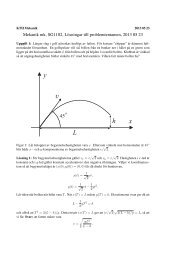
In a numerical study by Steen (1991) <strong>of</strong> flocculation in turbulent flows,<br />
a measure for the rate <strong>of</strong> rupture and aggregation in pipe flow and backward<br />
facing step flow was introduced. Shear flow is one flow condition in where this
3.4. PULP SUSPENSIONS 21<br />
is obtained but extensional flow is shown <strong>to</strong> be more efficient in dispersing <strong>fibre</strong><br />
flocs. This was first demonstrated by Kao & Mason (1975) and experimentally<br />
verified by Norman & Duffy (1977). Studies <strong>of</strong> floc rupture in shear flow has<br />
also been made by Lee & Brodkey (1987) and flow rupture in extensional flow<br />
was studied by James et al. (2003). In a work by Blaser (2000) the mechanism<br />
<strong>of</strong> shear and strain on floc motion was presented but not for pulp <strong>suspensions</strong>.<br />
However, the observations are similar <strong>to</strong> what has been reported for pulp suspension<br />
flows.<br />
Soszynski & Kerekes (1988) confirmed the influence <strong>of</strong> bending stresses on<br />
floc strength through stress relaxation experiments. They defined the propensity<br />
for paper-making <strong>fibre</strong>s <strong>to</strong> flocculate in terms <strong>of</strong> a dimensionless number,<br />
termed the crowding number N<br />
N = 2 2<br />
cvr<br />
3<br />
(3.8)<br />
where cv is the volume fraction <strong>of</strong> the solid material in the suspension, and<br />
r is the <strong>fibre</strong> aspect ratio. The physical significance <strong>of</strong> N can be seen in its<br />
definition: N reflects the number <strong>of</strong> <strong>fibre</strong>s in a spherical volume <strong>of</strong> diameter<br />
equal <strong>to</strong> unity. This definition can be <strong>related</strong> <strong>to</strong> the more widely used measure<br />
<strong>of</strong> particle concentration–the number <strong>of</strong> particles per unit volume (n) through<br />
n = 6N/(πl 3 p). Flocculation does not generally occur when N ≪1, as each <strong>fibre</strong><br />
can rotate freely. In the range 1 < N < 60, <strong>fibre</strong>s flocculate in simple shear flow<br />
see e.g. Soszynski & Kerekes (1988). It is in this range that most <strong>papermaking</strong><br />
processes operate. Fibre mobility is greatly hindered when N > 60, as the<br />
suspension forms networks, with each <strong>fibre</strong> making contact with on average<br />
three other closely located <strong>fibre</strong>s, see Meyer & Wahren (1964). The crowding<br />
number was supplemented by a <strong>fibre</strong> Reynolds number and a force fac<strong>to</strong>r in an<br />
overview by Kerekes (1995). The use <strong>of</strong> a crowding number has been further<br />
extended by Kiviranta & Dodson (1995) in characterising the mix conditions<br />
during paper forming.<br />
As previously mentioned, the rheologies <strong>of</strong> pulp <strong>suspensions</strong> are complex<br />
though important, since the interaction <strong>of</strong> the <strong>fibre</strong> suspension and the flow<br />
field results in some very specific characteristics (see Niskanan et al. (1998)<br />
and Björkman (1999)). In pipe flows at low flow velocities, pulp <strong>suspensions</strong><br />
will flow like plug flows. Plug flows characteristically flow has an almost homogenous<br />
velocity pr<strong>of</strong>ile is obtained through most <strong>of</strong> the pipe and close <strong>to</strong><br />
the wall a thin lubricating water layer is observable. As the velocity increases,<br />
the shear at the wall will cause rupturing at the individual <strong>fibre</strong> level or at the<br />
forming floc level, or both. This is referred <strong>to</strong> as turbulence in some cases, however<br />
there is a suggestion that it ought <strong>to</strong> be called fluidised flow (see Söderberg<br />
(1999)). As the velocity increases further, the centre plug flow gradually breaks<br />
up and becomes fluidised.<br />
In turbulence in a New<strong>to</strong>nian fluid, the continuous spectrum <strong>of</strong> scales are<br />
most probably influenced by the presence <strong>of</strong> <strong>fibre</strong>s in the flow. The small eddies,<br />
in order <strong>of</strong> the <strong>fibre</strong> size, are presumably suppressed and the larger eddies are
22 3. FLUID MECHANICS OF FIBRE SUSPENSION FLOWS<br />
Figure 3.4. Relative liquid-phase energy dissipation versus<br />
volumetric concentration for <strong>fibre</strong>s <strong>of</strong> different aspect ratios,<br />
A, and for a suspension <strong>of</strong> polyethylene beads. Result for <strong>fibre</strong><br />
<strong>suspensions</strong> with polyethylene <strong>fibre</strong>s or kraft <strong>fibre</strong> suspension<br />
(FBK) are shown in the study by Benning<strong>to</strong>n & Mmbaga<br />
(2001).<br />
influenced due <strong>to</strong> flocs and in overall this changes the turbulent spectrum. The<br />
dissipation <strong>of</strong> kinetic energy is changed, since energy is transferred from large<br />
scales <strong>to</strong> the <strong>fibre</strong> network. This turbulent modification was indicated in the<br />
study by Ljus et al. (2002) and also by Matas et al. (2003). In an experimental<br />
study by Benning<strong>to</strong>n & Mmbaga (2001), a reactive chemical was used in a<br />
pulp suspension <strong>of</strong> 4% and this indicated that 95% <strong>of</strong> the energy dissipation<br />
was transferred <strong>to</strong> direct <strong>fibre</strong> friction and only 5% <strong>of</strong> the energy dissipated in<br />
the fluid itself (see Figure 3.4). This experiment indicates that modification <strong>to</strong> a<br />
non-continuous spectrum by increasing the concentration <strong>of</strong> <strong>fibre</strong>s leads <strong>to</strong> nonlinear<br />
effects. This can be evidently be seen as an increase in the viscosity. In a<br />
study by Ralambotiana et al. (1997), the increase <strong>of</strong> viscosity due <strong>to</strong> changing<br />
the <strong>fibre</strong> aspect ratio and the concentration was studied, and revealed that this<br />
could be significant, with an increase in viscosity in the vicinity <strong>of</strong> 20-30%, even<br />
for very low concentrations.<br />
Recently, there has been extensive simulations by Klingenberg and his coworkers<br />
regarding <strong>fibre</strong> suspension <strong>of</strong> higher concentration, where entanglement<br />
and network <strong>of</strong> <strong>fibre</strong>s are expected. A model and technique for entangled <strong>fibre</strong>s<br />
and <strong>fibre</strong> network, flocs, is presented in Schmid et al. (2000). The flexibility<br />
<strong>of</strong> the <strong>fibre</strong>s are simulated in segments with forces and <strong>to</strong>rque in the segment<br />
joints.<br />
In the study by S<strong>to</strong>ckie & Green (1998) an approach <strong>of</strong> using a immersed<br />
boundary method in order <strong>to</strong> simulate the motion <strong>of</strong> flexible pulp <strong>fibre</strong>s. This
3.4. PULP SUSPENSIONS 23<br />
motion was calculated in a two-dimensional shear flow at moderate Reynolds<br />
number. A very recent work by Tornberg & Shelly (2004) numerically studied<br />
the dynamics <strong>of</strong> flexible <strong>fibre</strong>s in S<strong>to</strong>kes flow. Tornberg and Shelly used a<br />
non-local slender body theory and could obtain shear induced buckling and<br />
relaxation <strong>of</strong> the filaments, leading <strong>to</strong> an elastic energy concepts, which is very<br />
unique for a <strong>fibre</strong> suspension compared <strong>to</strong> suspension <strong>of</strong> spherical particles.<br />
In general, these effects are implicit in non-New<strong>to</strong>nian <strong>suspensions</strong>, however<br />
in pulp <strong>suspensions</strong> at low concentrations, viscosity may be simplified <strong>to</strong><br />
being constant and thus independent <strong>of</strong> the flow field. This implied that the<br />
suspension can be treated as New<strong>to</strong>nian as a first approximation. Simulations<br />
involving modelling <strong>of</strong> pulp <strong>suspensions</strong> are in their initial stage, however extensive<br />
experimental studies <strong>of</strong> pulp <strong>suspensions</strong> have been undertaken in parallel<br />
with the development <strong>of</strong> <strong>papermaking</strong> machines.
24 3. FLUID MECHANICS OF FIBRE SUSPENSION FLOWS
CHAPTER 4<br />
Summary <strong>of</strong> the papers<br />
Paper 1<br />
The first paper summarizes the pressure and wire position measurements performed<br />
in an experimental facility called the KTH-Former. The KTH-Former<br />
intends <strong>to</strong> model mechanisms in the roll forming zone <strong>of</strong> a paper machine. It<br />
includes a headbox, a roll and a wire, which can reproduce a one-sided dewatering<br />
event. Measurements were carried out with pure water for three different<br />
wires: non-permeable, semi-permeable and conventional open wire. Although<br />
not useful in <strong>papermaking</strong>, the non-permeable wire is relevant when trying <strong>to</strong><br />
understand the mechanisms <strong>of</strong> roll forming. In the study, the pressure pr<strong>of</strong>ile<br />
and the distance between the solid roll and the wire was measured along the<br />
wrap angle on the roll. The wrap angle is measured from the position were<br />
the free-jet from the headbox impinges on the wire <strong>to</strong> the point where the wire<br />
separates from the roll, Figure 4.1. Depending on the wrap angle the forming<br />
roll can result in partial or complete roll dewatering. For the case <strong>of</strong> partial<br />
dewatering the web is still saturated at the point where it separates from the<br />
roll. The measured pressure distribution showed a more complex pattern than<br />
the simple model p = T/R, which normally is referred <strong>to</strong> as the nominal pressure<br />
(T is wire tension and R roll radius). An example <strong>of</strong> an obtained pressure<br />
distribution for the non-permeable wire is shown in Figure 4.3.<br />
It is shown that an increase in wire tension has a similar effect as a decrease<br />
in flow-rate (jet flow rate from the headbox) on the shape <strong>of</strong> the pressure<br />
distribution. This is a consequence <strong>of</strong> that the flow <strong>to</strong> a large extent is governed<br />
by the relation between the dynamic pressure and the nominal pressure. For<br />
the case <strong>of</strong> partial dewatering the suction peak that appears at the roll-wire<br />
separation point has a strong influence on the pressure distribution upstream.<br />
Finally, it is shown that the drainage has a stabilizing effect on the dewatering<br />
pressure.<br />
Paper 2<br />
This paper formulates a physical model that is intended <strong>to</strong> explain fundamental<br />
mechanisms that control partial dewatering in roll forming in <strong>papermaking</strong>.<br />
The flow around the forming roll is modelled in a cylindrical coordinate system<br />
and the wire is assumed <strong>to</strong> be impermeable. The governing equations are<br />
reduced based on a discussion where the magnitude <strong>of</strong> the different terms is<br />
25
26 4. SUMMARY OF THE PAPERS<br />
¢¡ ¤£<br />
¢ <br />
¥ ¤ ¤<br />
¨ <br />
<br />
¥¡ ¦¨§<br />
<br />
<br />
<br />
<br />
<br />
<br />
¥¡ ¦¨©<br />
¢¡ ¤<br />
¥ <br />
¥¥ ¥¥ ¤¢ <br />
¤ ¤¢¢ ¤<br />
Figure 4.1. Wire position as function <strong>of</strong> normalized wrap angle<br />
for five different nominal pressures p = T/R. The dashed<br />
line corresponds <strong>to</strong> the outer measurement range <strong>of</strong> the position<br />
transducer and the dotted line corresponds <strong>to</strong> a possible<br />
wire path for the 7.5 kPa case.<br />
estimated. Given this reduced set <strong>of</strong> equations a non-linear equation for the<br />
position <strong>of</strong> the wire is deduced.<br />
This equation clearly shows that one <strong>of</strong> the most important parameters<br />
is the Weber number, We, which is the non-dimensional number that can be<br />
obtained by comparing the effect <strong>of</strong> wire tension (surface tension) in relation<br />
<strong>to</strong> the momentum <strong>of</strong> the incoming headbox jet.<br />
The non-linear equation is linearized around the trivial solution <strong>to</strong> the<br />
equations, which gives that the wire is displaced a constant distance from the<br />
roll along the whole wrap length. The linear equation is shown <strong>to</strong> have a standing<br />
wave solution that gives a specific wavelength. This solution is compared <strong>to</strong><br />
previously measured data (see Paper 1 ) regarding the wavelength <strong>of</strong> the waves<br />
and showed in Figure 4.3<br />
Clearly the permeability <strong>of</strong> the wires (and the <strong>fibre</strong> mats formed at the<br />
wires) has a strong influence on the flow in the roll-forming zone <strong>of</strong> a paper<br />
machine. However, the experimental results obtained in Paper 1 show that<br />
standing waves also are present with a permeable wire. Hence, given a specific<br />
forming situation there will probably be a threshold value for the Weber number.<br />
On one side <strong>of</strong> this value the process will be stable and on the other side<br />
waves will appear.<br />
The result pinpoints the importance <strong>of</strong> the Weber number, which also can<br />
be <strong>of</strong> importance on a day-<strong>to</strong>-day basis in a modern paper mill.
4. SUMMARY OF THE PAPERS 27<br />
<br />
<br />
¢ ¢ <br />
Figure 4.2. The measured pressure distributions at the roll<br />
surface with the non-permeable wire for different nominal pressures<br />
(changed the wire tension T ).<br />
Non-dimensional wave number<br />
16<br />
14<br />
12<br />
10<br />
8<br />
6<br />
4<br />
2<br />
Theoretical result<br />
Experimental result<br />
0<br />
0.5 0.6 0.7 0.8 0.9 1.0 1.1 1.2<br />
Weber number<br />
Figure 4.3. Normalised wave number <strong>to</strong> Weber number, We,<br />
for the case <strong>of</strong> non-permeable wire. Experimental result refer<br />
<strong>to</strong> data obtained in Paper 1.
28 4. SUMMARY OF THE PAPERS<br />
Paper 3<br />
In this study the sedimentation <strong>of</strong> rigid <strong>fibre</strong>s at a finite but small Reynolds<br />
number has been studied. Understanding <strong>of</strong> the settling motion <strong>of</strong> dilute <strong>fibre</strong><br />
<strong>suspensions</strong> is difficult as each individual <strong>fibre</strong> moves under the influence <strong>of</strong><br />
the long-range hydrodynamic disturbances <strong>of</strong> the other <strong>fibre</strong>s. Insight in<strong>to</strong> this<br />
phenomena can be gained by first examining the simplest case <strong>of</strong> the motion<br />
<strong>of</strong> a single isolated <strong>fibre</strong> settling under S<strong>to</strong>kes’ flow conditions.<br />
Unlike spheres, isolated <strong>fibre</strong>s can have significant motion perpendicular<br />
<strong>to</strong> gravity with a drift velocity strongly dependent upon its orientation. With<br />
swarms <strong>of</strong> settling <strong>fibre</strong>s this situation becomes more complex as each individual<br />
<strong>fibre</strong> moves under the influence <strong>of</strong> the long-range hydrodynamic disturbances<br />
<strong>of</strong> the other particles. These forces tend <strong>to</strong> affect the motion <strong>of</strong> the neighboring<br />
particles and lead <strong>to</strong> inhomogeneous settling rates.<br />
As shown in Figure 4.4, two distinct settling behaviours were observed.<br />
The settling velocity <strong>of</strong> these <strong>fibre</strong>s display somewhat similar behaviour as<br />
that reported by Herzhaft & Guazzelli (1999) and by Herzhaft et al. (1996),<br />
i.e. non-mono<strong>to</strong>nic for small volume concentration. We did observe individual<br />
<strong>fibre</strong>s, however, with velocities approximately four-times that <strong>of</strong> the isolated<br />
<strong>fibre</strong>. In addition we observed the trajec<strong>to</strong>ries <strong>of</strong> the <strong>fibre</strong>s and classified the<br />
observed motion in<strong>to</strong> three groups: simple downward or upward motion with<br />
drift; recirculating or meandering motion; or groups <strong>of</strong> <strong>fibre</strong>s with cor<strong>related</strong><br />
motion. We observed <strong>fibre</strong>s with cor<strong>related</strong> motion over length scales greater<br />
that 2lp (lp is <strong>fibre</strong> length). We interpreted this as evidence <strong>of</strong> particle clumping.<br />
In the semi-dilute regime, <strong>fibre</strong>s recirculated in swirls which appeared as<br />
eddy-like structures <strong>of</strong> size ≈ 15 − 20 lp, see Figure 4.5. Over the concentration<br />
ranges tested, we characterized the velocity fluctuations as the standard deviation<br />
σ <strong>of</strong> the his<strong>to</strong>gram and find that both the drift and settling fluctuations<br />
are proportional <strong>to</strong> φ 1/3 , similar <strong>to</strong> the findings reported Segre et al. (1997) for<br />
settling spheres.<br />
Paper 4<br />
The purpose <strong>of</strong> this experimental work was <strong>to</strong> study the wall effect, or influence<br />
<strong>of</strong> shear, on <strong>fibre</strong> orientation in <strong>suspensions</strong> with different <strong>fibre</strong> aspect ratios<br />
and concentrations. We have studied a suspension flow on an inclined plate.<br />
The <strong>fibre</strong> orientation at different wall parallel planes were measured.<br />
We have applied an index-<strong>of</strong>-refraction (IR) matching method <strong>to</strong> gain optical<br />
access in<strong>to</strong> the <strong>fibre</strong> suspension. IR-matching was used <strong>to</strong>gether with<br />
particle tracking techniques and the <strong>fibre</strong> orientation was extracted using a<br />
two-dimensional wavelet transform using LabView.<br />
For low concentration (nL 3 =0.009 and nL 3 =0.09) and low aspect ratio<br />
(r=10) <strong>fibre</strong>s are oriented perpendicular <strong>to</strong> the streamwise direction in the<br />
near wall region, see an representative result in Figure 6.
Normalized Velocity /V i<br />
1<br />
0.8<br />
0.6<br />
0.4<br />
0.2<br />
0<br />
−0.2<br />
Drift<br />
Settling<br />
4. SUMMARY OF THE PAPERS 29<br />
0 2 4 6 8 10 12 14 16 18<br />
x 10 −3<br />
Solidity φ<br />
Figure 4.4. The normalized average settling and horizontal<br />
drift velocities as a function <strong>of</strong> volume concentration φ for aspect<br />
ratios r = 23 (◦) and r = 50 (). The settling velocity<br />
is defined by V and the drift velocity by V⊥. The uncertainty<br />
in the data is represented the standard error <strong>of</strong> the mean estimated<br />
at the 95% confidence interval.<br />
An increase in <strong>fibre</strong> concentrations result in increased hydrodynamic interactions<br />
in the <strong>fibre</strong> suspension. However, the present results show an effect on<br />
<strong>fibre</strong> orientation for twice the distance in<strong>to</strong> the suspension compared <strong>to</strong> what<br />
has previously been reported (see for example Russel et al. (1977)). The influence<br />
was observed as a wider <strong>fibre</strong> orientation distribution and as a shift in the<br />
maximum <strong>fibre</strong> orientation.<br />
Paper 5<br />
A technique <strong>of</strong> ultrasound <strong>to</strong> measure fluid velocity non-intrusively in opaque<br />
fluids has been tested and evaluated. The ultimate goal, <strong>of</strong> which the present<br />
work provides the first steps, is <strong>to</strong> measure turbulent flow properties in cellulose<br />
<strong>fibre</strong> <strong>suspensions</strong>. The idea is is <strong>to</strong> determine the velocity <strong>of</strong> the flow from<br />
ultrasound echoes reflected by particles in the fluid, see Figure 8.<br />
A commercial Ultra Velocity Pr<strong>of</strong>iler unit, which determines the velocity<br />
based on the doppler shift <strong>of</strong> the ultrasound frequency is tested. The commercial<br />
unit is found <strong>to</strong> be suitable for measurements <strong>of</strong> mean properties. However,<br />
the spatial and/or temporal resolution <strong>of</strong> the measurements is limited. The unit<br />
is thus not suitable for measurements <strong>of</strong> turbulent velocity fluctuations. These<br />
limitations might be surmountable by alternative signal processing. A number
30 4. SUMMARY OF THE PAPERS<br />
vertical direction [mm]<br />
vertical direction [mm]<br />
120<br />
110<br />
100<br />
90<br />
80<br />
70<br />
a)<br />
60<br />
0 10 20 30 40 50 60<br />
horizontal direction [mm]<br />
120<br />
110<br />
100<br />
90<br />
80<br />
70<br />
60<br />
0 10 20 30 40 50 60<br />
horizontal direction [mm]<br />
c)<br />
vertical direction [mm]<br />
vertical direction [mm]<br />
120<br />
110<br />
100<br />
90<br />
80<br />
70<br />
b)<br />
60<br />
0 10 20 30 40 50 60<br />
horizontal direction [mm]<br />
120<br />
110<br />
100<br />
90<br />
80<br />
70<br />
d)<br />
60<br />
0 10 20 30 40 50 60<br />
horizontal direction [mm]<br />
Figure 4.5. PIV results on <strong>fibre</strong> aspect ratio r = 23 suspension<br />
at volume concentration φ = 1.4 × 10 −2 sampled at the<br />
midplane in the sedimentation cell. Four different times are<br />
shown (a) 16.5s (b) 16.9s (c) 17.3s and (d) 17.7s. The image<br />
can be scaled using 1.4mm ↦→ 1mm/s.<br />
<strong>of</strong> methods are proposed and some are evaluated. It is believed that ultrasound<br />
based methods will be useful in the characterisation <strong>of</strong> turbulent flow in <strong>fibre</strong><br />
<strong>suspensions</strong>.
Fibre fraction, n/ N <strong>to</strong> t<br />
Fibre fraction, n/ N <strong>to</strong>t<br />
0.25<br />
0.2<br />
0.15<br />
0.1<br />
0.05<br />
a)<br />
0<br />
0 30 60 90<br />
Fibre orientation<br />
0.25<br />
0.2<br />
0.15<br />
0.1<br />
0.05<br />
c)<br />
0<br />
0 30 60 90<br />
Fibre orientation<br />
4. SUMMARY OF THE PAPERS 31<br />
Fibre fraction, n/ N <strong>to</strong>t<br />
Fibre fraction, n/ N <strong>to</strong>t<br />
0.25<br />
0.2<br />
0.15<br />
0.1<br />
0.05<br />
b)<br />
0<br />
0 30 60 90<br />
Fibre orientation<br />
0.25<br />
0. 2<br />
0.15<br />
0. 1<br />
0.05<br />
d)<br />
0<br />
0 30 60 90<br />
Fibre orientation<br />
Figure 4.6. The <strong>fibre</strong> orientation distributions for r = 10<br />
and concentration nL 3 =0.009 for different wall parallel plans,<br />
a) z = 1 ± 1 mm b) z = 3 ± 1 mm, c) z = 6 ± 1 mm and d)<br />
z = 9 ± 1 mm.<br />
Figure 4.7. Ultrasonic velocity measurement by determining<br />
the Doppler shift from the wavelet transform.
32 4. SUMMARY OF THE PAPERS
CHAPTER 5<br />
Papers and authors contributions<br />
The scientific papers and the authors contribution as well as where the results<br />
have been presented.<br />
Paper 1. Holm R., Söderberg D. & Norman B., 2004 Experimental studies on<br />
the partial dewatering during roll forming <strong>of</strong> paper, <strong>to</strong> appear in Nordic Pulp<br />
and Paper Research J.<br />
RH has designed the experiment based on discussions with the co-authors<br />
(DS, BN). RH has carried out the experiments and evaluated the data. RH has<br />
<strong>to</strong>gether with the co-authors prepared the paper. In addition, Pr<strong>of</strong>. P.H.Alfredsson,<br />
KTH Mechanics has contributed <strong>to</strong> all parts <strong>of</strong> the work.<br />
Paper 2. Holm R., & Söderberg D., 2004 A theoretical analysis <strong>of</strong> the flow stability<br />
in roll forming <strong>of</strong> paper, <strong>to</strong> appear in Nordic Pulp and Paper Research J.<br />
The theoretical analysis, the evaluation <strong>of</strong> the results and preparation <strong>of</strong><br />
the paper has been perfomed by RH <strong>to</strong>gether with DS. Data for these two<br />
paper has its origin from the licentiate thesis <strong>of</strong> RH, Holm (2002). Part <strong>of</strong> the<br />
results has been presented at PAPTAC, 89 th Annual Meeting PAPTAC 2003,<br />
Montreal, Canada.<br />
Paper 3. Holm R., S<strong>to</strong>rey, S., Martinez M., & Söderberg D. 2004, Visualization<br />
<strong>of</strong> streaming-like structures during settling <strong>of</strong> dilute and semi-dilute rigid<br />
<strong>fibre</strong> <strong>suspensions</strong>, submitted <strong>to</strong> Physics <strong>of</strong> <strong>Fluid</strong>s<br />
RH has performed the experiments in collaboration with SS under the supervision<br />
<strong>of</strong> MM. RH carried out the PIV-measurements and the post-processing<br />
<strong>of</strong> the data. The data evaluation algorithm was developed by DS and modified<br />
by RH. The paper was written by RH, primarily <strong>to</strong>gether with MM. The experiments<br />
were conducted at University <strong>of</strong> British Columbia, Vancouver, Canada.<br />
Part <strong>of</strong> the results was presented at the Paper Physics seminar, 2004 in Trondheim,<br />
Norway.
34 5. PAPERS AND AUTHORS CONTRIBUTIONS<br />
Paper 4. Holm R. & Söderberg D. 2004 Influence <strong>of</strong> shear on <strong>fibre</strong> orientation<br />
in the near wall region, <strong>to</strong> be submitted<br />
RH has designed the experiment based on discussions with the co-author<br />
DS. RH has carried out the measurement and evaluated the data. The data<br />
evaluation algorithm was developed by DS and modified by RH. RH has <strong>to</strong>gether<br />
with DS prepared the paper.<br />
Paper 5. Fällman M., Holm R., Lundell F. & Söderberg D. 2004 The use <strong>of</strong><br />
ultrasonic measurement in <strong>suspensions</strong>, STFI-Packforsk report, PUB 20, 2004.<br />
RH has designed the experiment <strong>to</strong>gether with DS and RH participated in<br />
the development <strong>of</strong> a modified UVP-technique <strong>to</strong>gether with MF and FL. RH<br />
has participated in the analysis <strong>of</strong> the technique and supported MF and FL in<br />
the preparation <strong>of</strong> the paper.
APPENDIX A<br />
Single-sided roll forming<br />
The experimental findings <strong>of</strong> the pressure pr<strong>of</strong>ile, wire position and the expelled<br />
amount <strong>of</strong> water are shown in Figure A.1. These measurements were conducted<br />
in partial dewatering in single-side roll forming, with a semi-permeable wire<br />
and water <strong>to</strong> simulate the mechanism <strong>of</strong> web build up in paper making. The<br />
measurements with the saveall was a time consuming procedure, during which<br />
the system was challenged when keeping a constant flow <strong>of</strong> 400 l/min in the<br />
KTH-Former. The mean drainage rate (over ˆϕ=0.005) is shown <strong>to</strong>gether with<br />
the corresponding pressure and wire position for the semi-permeable case at<br />
a nominal pressure <strong>of</strong> 5.9 kPa. From the figure, it is clearly seen that the<br />
amount <strong>of</strong> expelled water agrees well with the pressure pr<strong>of</strong>ile, with two significant<br />
peaks and a minimum around ˆϕ=0.12. Even if there are experimental<br />
challenges <strong>to</strong> adjust the saveall <strong>to</strong> get sufficiently close <strong>to</strong> the wire <strong>to</strong> collect the<br />
expelled water without <strong>to</strong>uching the wire. The result from the saveall measurements<br />
showed that approximately 30 % <strong>of</strong> the <strong>to</strong>tal flow was drained within<br />
the dewatering zone. This means that a substantial amount <strong>of</strong> the water passes<br />
through the dewatering zone, so this case can indeed be described as partial<br />
dewatering.<br />
One way <strong>of</strong> checking the consistency <strong>of</strong> the experimental data is <strong>to</strong> integrate<br />
the pressure data <strong>to</strong> determine the corresponding wire positions. The relation<br />
between the pressure and the position is given by equation (A.1).<br />
pwire = T 1<br />
R − g′′ (s) , (A.1)<br />
where T is the wire tension [N/m], R is the roll radius [m] and g(s) is the distance<br />
between the roll surface and the position <strong>of</strong> the wire along the coordinate<br />
s, s = ϕR.<br />
The results from such integrations are shown in Figure A.2 where the measured<br />
wire position and the calculated position based on the pressure data are<br />
shown. The calculated positions show good agreement with the measured ones.<br />
However, the calculated data points starts <strong>to</strong> deviate from the measured ones<br />
if the position <strong>of</strong> the second boundary condition is chosen downstream <strong>of</strong> the<br />
inflection point in the wire positions (at ˆϕ ≈ 0.17). The upstream point for<br />
35
36 A. SINGLE-SIDED ROLL FORMING<br />
Pressure [kPa], Wire position [mm]<br />
16<br />
14<br />
12<br />
10<br />
8<br />
6<br />
4<br />
2<br />
0<br />
-2<br />
-4<br />
Pressure<br />
Position<br />
Drainage<br />
-6<br />
0.05 0.1 0.15 0.2<br />
Normalised wrap angle<br />
Figure A.1. The measured pressure and wire position with<br />
the corresponding drainage rate, average data from figure ??.<br />
the calculation was chosen at ˆϕ=0.076. The deviation <strong>of</strong> the calculated position<br />
is obvious when chosen the second boundary condition at ˆϕ ≈ 0.19. We<br />
interpreted this as evidence <strong>of</strong> strong affect on the forming event due <strong>to</strong> the<br />
roll-wire separation.<br />
1.1<br />
1<br />
0.9<br />
0.8<br />
0.7<br />
0.6<br />
0.5<br />
0.4<br />
0.3<br />
0.2<br />
0.1<br />
0<br />
Drainage rate [l/min]
Wire position [mm]<br />
12<br />
10<br />
8<br />
6<br />
4<br />
2<br />
Estimated data<br />
Measured data<br />
A. SINGLE-SIDED ROLL FORMING 37<br />
0<br />
0.06 0.08 0.1 0.12 0.14 0.16 0.18 0.2<br />
Normalised wrap angle<br />
Figure A.2. Measured wire position and calculated position<br />
<strong>of</strong> the wire based on pressure data. Data obtained at nominal<br />
pressure 4.5 kPa and non-permeable wire
38 A. SINGLE-SIDED ROLL FORMING
Bibliography<br />
Acrivos, A. & Shaqfeh, E. S. G. 1988 The effective thermal conductivity and<br />
elongational viscosity <strong>of</strong> a non-dilute suspension <strong>of</strong> aligned slender rods. Phys.<br />
<strong>Fluid</strong>s. 31, 1841–1844.<br />
Anczurowski, E. & Mason, S. G. 1967 The kinetics <strong>of</strong> flowing dispersions iii.<br />
equilibrium orientations <strong>of</strong> rods and discs (experimental). J. Colloid Int. Sci.<br />
23, 533–546.<br />
Andersson, O. 1966 Some observation on <strong>fibre</strong> <strong>suspensions</strong> in turbulent motion.<br />
Svensk Papperstidn. 69 (2), 23–31.<br />
Bandhakavi, V. & Aidun, C. 1999 Analysis <strong>of</strong> turbulent flow in the converging<br />
zone <strong>of</strong> a headbox. In Tappi Engineering Conference, Annaheim, pp. 1135–1154.<br />
Batchelor, G. K. 1970a Slender-body theory for particles if arbitrary cross-section<br />
in s<strong>to</strong>kes flow. J. <strong>Fluid</strong> Mech. 44 (3), 419–440.<br />
Batchelor, G. K. 1970b The stress system in a suspension <strong>of</strong> force-free particles.<br />
J. <strong>Fluid</strong> Mech. 41 (3), 545–570.<br />
Batchelor, G. K. 1971 The stress generated in a non-dilute suspension <strong>of</strong> elongated<br />
particles by pure straining motion. J. <strong>Fluid</strong> Mech. 46 (4), 813–829.<br />
Benning<strong>to</strong>n, C. & Mmbaga, J. 2001 Liquid phase turbulence in pulp <strong>fibre</strong> <strong>suspensions</strong>.<br />
Proc.The 12th Fundamental Research Symposium, Oxford.<br />
Bergström, R. 2003 Fibre flocculation during twin-wire roll forming. Lic thesis,<br />
Div. Paper Tech., Dept. Fibre and Polymer Tech., KTH, S<strong>to</strong>ckholm.<br />
Björkman, U. 1999 Flow <strong>of</strong> flocculated <strong>fibre</strong>s. Kungl Tekniska Högskolan, avd. Pappersteknik.<br />
Blaser, S. 2000 Flocs in shear and strain flows. J. Colloid and Interface Sci. 225 (-),<br />
273–284.<br />
Brether<strong>to</strong>n, F. P. 1962 The motion <strong>of</strong> rigid particles in a shear flow at low Reynolds<br />
number. J. <strong>Fluid</strong> Mech. 14, 284–304.<br />
Burger, J. M. 1938 On the motion <strong>of</strong> small particles <strong>of</strong> elongated form suspended<br />
in a viscous liquid: 2nd report on viscosity and plasticity. North-Holland Publ.,<br />
Amsterdam.<br />
Chen, E., Schultz, W. & Perkins, N. 1998 A two-dimensional viscous model <strong>of</strong> a<br />
wet paper forming process. In Tappi Engineering Conference, pp. 21–.<br />
39
40 BIBLIOGRAPHY<br />
Chuang, S. 1982 Microturbulence generation in a papermachine headbox. In Tappi<br />
Engineering Conference, pp. 205–213.<br />
Cox, R. G. 1970 The motion <strong>of</strong> long slender bodies in a viscous fluid, part 1 general<br />
theory. J. <strong>Fluid</strong> Mech. 44 (4), 791–810.<br />
Crowe, C. T., Sommerfeldt, M. & Tsuji, Y. 1998 Multiphase flows with droplets<br />
and particles. CRC Press LLC.<br />
Dalpke, B. 2002 Modelling <strong>of</strong> jet impingement and early roll forming. PhD thesis,<br />
Dept. <strong>of</strong> Mechanical engineering, University <strong>of</strong> British Colombia, Vancouver.<br />
Dinh, S. M. & Armstrong, R. C. 1984 A rheological equation <strong>of</strong> state for semiconcentrated<br />
<strong>fibre</strong> suspension. J. Rheol. 28, 207–227.<br />
Doi, M. & Edwards, S. F. 1986 The theory <strong>of</strong> polymer dynamics. Oxford University<br />
Press.<br />
Farring<strong>to</strong>n, T. A. 1991 A numerical investigation <strong>of</strong> three tissue machine headboxes.<br />
In AIChE Proceedings, Forest Products Symposium, pp. 177–188.<br />
Fellers, C. & Norman, B. 1998 Pappersteknik. Kungl Tekniska Högskolan, avd.<br />
Pappersteknik.<br />
Folgar, F. & Tucker, C. L. 1984 Orientation behavior <strong>of</strong> <strong>fibre</strong>s in concentrated<br />
<strong>suspensions</strong>. J. Rheinf. Plast. Composites 3, 98–119.<br />
Gooding, R., McDonald, D. & Rompr, A. 2001 Measurement <strong>of</strong> drainage around<br />
a forming roll. In 87th Annual Meeting, PAPTAC, Monteral, pp. A125–138.<br />
Herzhaft, B. & Guazzelli, E. 1999 Experimental study <strong>of</strong> the sedimentation <strong>of</strong><br />
dilute and semi-dilute <strong>suspensions</strong> <strong>of</strong> <strong>fibre</strong>s. J. <strong>Fluid</strong> Mech. 348 (-), 133–158.<br />
Herzhaft, B., Guazzelli, E., Mackaplow, M. B. & Shaqfeh, E. S. G. 1996<br />
Experimental investigation <strong>of</strong> the sedimentation <strong>of</strong> dilute <strong>fibre</strong> <strong>suspensions</strong>. Phys.<br />
Rev. Lett. 77 (2), 290–293.<br />
Hinch, E. J. & Leal, L. P. 1972 The effect <strong>of</strong> Brownian motion on the rheology<br />
properties <strong>of</strong> a suspension <strong>of</strong> non-spherical particles. J. <strong>Fluid</strong> Mech. 52, 683–712.<br />
Holm, R. 2002 On the fluid <strong>mechanics</strong> <strong>of</strong> partial dewatering during roll forming in<br />
paper making Lic thesis, Dept. <strong>of</strong> Mech., Royal Institute <strong>of</strong> Technology (KTH),<br />
S<strong>to</strong>ckholm, Sweden.<br />
Holmqvist, C. 2002 Modelling <strong>of</strong> the pressure distribution in twin-wire blade formers<br />
Lic thesis, Dept. <strong>of</strong> Mech., Royal Institute <strong>of</strong> Technology (KTH), S<strong>to</strong>ckholm,<br />
Sweden.<br />
Hua, L. & et. al 1999 A numerical investigation <strong>of</strong> three tissue machine headboxes.<br />
In Tappi Engineering Conference, Annaheim, pp. 1123–1133.<br />
Hyensjö, M., Krochak, P., J.Olson, Hämäläinen, J. & Dahlkind, A. 2004<br />
Modelling a turbulent dilute <strong>fibre</strong> suspension in a planar contraction: Effect <strong>of</strong><br />
vane types, vane position and wall boundary layer on <strong>fibre</strong> orientation distribution.<br />
In 5th International Conference on Multiphase Flow, ICMF04 , p. 436.<br />
James, D. F., Yogachandran, N., R.Loewen, M., Liu, H. & Davis, A. M. J.<br />
2003 Floc rupture in extensional flow. J. Pulp and Paper Sci. 26 (11), 377–382.<br />
Jeffery, G. B. 1922 The motion <strong>of</strong> ellipsoidal particles immersed in a viscous fluid.<br />
Proc. Roy. Soc. London A, 161–179.
BIBLIOGRAPHY 41<br />
Kao, S. & Mason, S. 1975 Dispersion pf particles by shear. Nature 253 (20), 619–<br />
621.<br />
Kerekes, R. J. 1995 Perspectives on <strong>fibre</strong> flocculation in papermakin. In Int. Paper<br />
Physics conf., Niagara, pp. 23–31.<br />
Kerekes, R. J., Soszynski, R. M. & Tam-Doo, P. M. 1985 The flocculation <strong>of</strong><br />
pulp <strong>fibre</strong>s. Proc.The 8th Fundamental Research Symposium, Oxford. Pulp and<br />
Paper Centre, UBC Vancouver, Canada.<br />
Kiviranta, A. & Dodson, C. 1995 Evaluating Fourdrinier formation performance.<br />
J. Pulp Pap. Sci 21 (11), 379–384.<br />
Lee, C. W. & Brodkey, R. S. 1987 A visual study <strong>of</strong> pulp floc dispersion mechanisms.<br />
Am. Inst. Chem. Eng. J. 33 (2), 297–302.<br />
Ljus, C., Johansson, B. & Almstedt, A.-E. 2002 Turbulence modification by<br />
particles in a horizontal pipe flow. Int. J. Multiphase flow 28 (-), 1075–1090.<br />
Mackaplow, M. B. & Shaqfeh, E. S. G. 1998 A numerical study <strong>of</strong> the sedimentation<br />
<strong>of</strong> <strong>fibre</strong> <strong>suspensions</strong>. J. <strong>Fluid</strong> Mech. 376 (-), 149–182.<br />
Malashenko, A. & Karlsson, M. 2000 Twin wire forming - an overview. In 86th<br />
Annual Meeting PAPTAC, Monteral, pp. A189–201.<br />
Mason, S. G. & Manley, R. S. J. 1957 Particle motion in sheared <strong>suspensions</strong>:<br />
orientations and interaction <strong>of</strong> ridig rods. Proc. Roy. Soc. London A238, 117–<br />
131.<br />
Matas, J.-P., Morris, J. F. & Guazzelli, E. 2003 Transition <strong>to</strong> turbulence in<br />
particulate pipe flow. Phys. Review Lett. 90 (1), 014501–1–4.<br />
Meyer, R. & Wahren, D. 1964 On the elastic properties <strong>of</strong> three-dimensional <strong>fibre</strong><br />
networks. Svensk Papperstidn. 67 (10), 432–.<br />
Minier, J.-P. & Peirano, E. 2001 The pdf approach <strong>to</strong> turbulent polydispersed<br />
two-phase flows. Physics report 352, 1–214.<br />
Niskanan, K., Kajan<strong>to</strong>, I. & Pakarinen, P. 1998 Paper physics. Fapet OY/Paperi<br />
ja Puu Oy.<br />
Norman, B. 1989 Overview <strong>of</strong> the physics <strong>of</strong> forming. Proc.The 9th Fundamental<br />
Research Symposium, Oxford.<br />
Norman, B. & Duffy, G. 1977 Hydrodynamics <strong>of</strong> <strong>papermaking</strong> <strong>fibre</strong>s in water<br />
<strong>suspensions</strong>. Proc. Fibre-water interactions in <strong>papermaking</strong>, Oxford.<br />
Norman, B. & Söderberg, D. 2001 Overview <strong>of</strong> forming literature 1990-2000.<br />
Proc.The 12th Fundamental Research Symposium, Oxford.<br />
Parsheh, M. 2001 Flow in contractions with application <strong>to</strong> headboxes. PhD thesis,<br />
Dept. <strong>of</strong> Mechanics, KTH, S<strong>to</strong>ckholm.<br />
Petrie, C. J. S. 1999 The rheology <strong>of</strong> <strong>fibre</strong> <strong>suspensions</strong>. J. Non-New<strong>to</strong>nian <strong>Fluid</strong><br />
Mech. 87 (2-3), 369–402.<br />
Pope, S. B. 2000 Turbulent flows. Cambrigde University Press.<br />
Rahnama, M., Koch, D. L. & Shaqfeh, E. S. G. 1995 The effect <strong>of</strong> hydrodynamic<br />
interactions on the orientation distribution in a <strong>fibre</strong> suspension subject <strong>to</strong> simple<br />
shear flow. Phys. <strong>Fluid</strong>s 7 (3), 487–506.<br />
Ralambotiana, T., Blanc, R. & Chaouche, M. 1997 Viscosity scaling in <strong>suspensions</strong><br />
<strong>of</strong> non-Brownian rodlike particles. Phys. <strong>Fluid</strong>s 9 (12), 3588–3594.
42 BIBLIOGRAPHY<br />
Russel, W. B., Hinch, E. J., Leal, L. G. & Tieffenbruck, G. 1977 Rods falling<br />
near vertical wall. J. <strong>Fluid</strong> Mech. 83 (2), 273–287.<br />
Schlichting, H. 1999 Boundary layer theory. McGraw-Hill.<br />
Schmid, C. F., Switzer, L. H. & Klingenberg, D. 2000 Simulation <strong>of</strong> <strong>fibre</strong> flocculation:<br />
effect <strong>of</strong> fiber properties and interfiber friction. J. Rheology 44 (4),<br />
781–809.<br />
Segre, P. H., Herbolzheimer, E. & Chaikin, P. M. 1997 Long-range correlations<br />
in sedimentation. Phys Rev Lett 79 (13), 2574–2577.<br />
Shands, J. 1991 Mechanics <strong>of</strong> s<strong>to</strong>ck jump at jet impingement. J. Pulp Pap. Sci<br />
17 (3), 92–99.<br />
Shaqfeh, E. S. G. & Fredrickson, G. H. 1990 The hydrodynamic stress in a<br />
suspension <strong>of</strong> rods. Phys. <strong>Fluid</strong>s A. 2, 7–24.<br />
Shaqfeh, E. S. G. & Koch, D. L. 1988 The effect <strong>of</strong> hydrodynamic interactions on<br />
the orientation <strong>of</strong> axissymmetric particles flowing through a fixed-bed <strong>of</strong> spheres<br />
or <strong>fibre</strong>s. Phys. <strong>Fluid</strong>s 31, 728–743.<br />
Söderberg, D. 1999 Hydrodynamics <strong>of</strong> plane liquid jets aimed at applications in<br />
paper manufacturing. PhD thesis, Dept. <strong>of</strong> Mechanics, KTH, S<strong>to</strong>ckholm.<br />
Soszynski, R. M. & Kerekes, R. J. 1988 Elastic interlocking <strong>of</strong> nylon <strong>fibre</strong>s suspended<br />
in liquid, part 2: process <strong>of</strong> interlocking. Nordic Pulp and Paper Research<br />
J. 3 (4), 180–.<br />
Steen, M. 1991 Modeling <strong>fibre</strong> flocculationin turbulent flows: a numerical study.<br />
Tappi J. 74 (9), 175–181.<br />
Steenberg, B., Olsson, S. & Wahren, D. 1961 Studies on pulp crill. Svensk<br />
Papperstidn. 64 (17), 634–637.<br />
Steenberg, B. & Wahren, D. 1961 Concentration gradients in boundary layers <strong>of</strong><br />
streaming <strong>fibre</strong> <strong>suspensions</strong>. Svensk Papperstidn. 63 (11), 347–355.<br />
S<strong>to</strong>ckie, J. M. & Green, S. I. 1998 Simulating the motion <strong>of</strong> flexible pulp <strong>fibre</strong>s<br />
using the immersed boundary method. J. Comput. Physics 147 (1), 147–165.<br />
S<strong>to</strong>ver, C. A., Koch, D. L. & Cohen, C. 1992 Observation <strong>of</strong> <strong>fibre</strong> orientation in<br />
simple shear flow <strong>of</strong> semi-dilute <strong>suspensions</strong>. J. <strong>Fluid</strong> Mech. 238, 277–296.<br />
Tornberg, A.-K. & Shelly, M. J. 2004 Simulating the dynamics and interactions<br />
<strong>of</strong> flexible <strong>fibre</strong>s in s<strong>to</strong>kes flow. J. Comput. Physics 196 (1), 8–40.<br />
Trevelyan, B. J. & Mason, S. G. 1951 Particle motions in sheared <strong>suspensions</strong>,<br />
part i rotations. J. Colloid Sci. 6, 354–367.<br />
Trit<strong>to</strong>n, D. J. 1988 Physical <strong>Fluid</strong> Dynamics. Oxford University Press.<br />
Turnbull, P. F., Perkins, N. C., Schultz, W. W. & Beuther, P. D. 1997<br />
One-dimensional dynamic model <strong>of</strong> a paper forming process. Tappi Journal 80,<br />
245–252.<br />
Zahrai, S. 1997 On the fluid <strong>mechanics</strong> <strong>of</strong> twin-wire formers. PhD thesis, Dept. <strong>of</strong><br />
Mechanics, KTH, S<strong>to</strong>ckholm.<br />
˚Akesson, K. 2004 Floc behaviour in a twin-wire blade pressure pulse. Lic thesis,<br />
Div. Paper Tech., Dept. Fibre and Polymer Tech., KTH, S<strong>to</strong>ckholm.
Acknowledgements<br />
During this PhD-project there have been several persons involved, maybe because<br />
it covers several fields or simple because it is interesting. However, one<br />
person has been endlessly patient and helpful, Dr. Daniel Söderberg.<br />
I have <strong>to</strong> express my gratitude <strong>to</strong> Pr<strong>of</strong>. Gustav Amberg, Pr<strong>of</strong>. Henrik<br />
Alfredsson and Pr<strong>of</strong>. Fritz Bark at KTH Mechanics for a guiding hand at different<br />
stages during the work. Pr<strong>of</strong>. Bo Norman at Div. <strong>of</strong> Paper Technology,<br />
KTH, for comments regarding <strong>papermaking</strong>. For industrial point <strong>of</strong> views, I<br />
thanks the industrial partners within the network FaxénLabora<strong>to</strong>riet and foremost<br />
Dr.Lars Martinsson at Albany International AB. My gratitude also goes<br />
<strong>to</strong> Pr<strong>of</strong>. Mark Martinez at Dept. <strong>of</strong> Chemical and Biological Engineering,<br />
University <strong>of</strong> British Columbia (UBC), Vancouver for guiding me in<strong>to</strong> the field<br />
<strong>of</strong> <strong>fibre</strong> <strong>suspensions</strong> and Jean-Pierre Minier at Electricité de France, Paris, for<br />
introducing me <strong>to</strong> two-phase flows. My college Claes Holmqvist is gratefully<br />
acknowledged for his contribution in pro<strong>of</strong>-reading my manuscript.<br />
I would also like <strong>to</strong> thank all my colleagues at KTH Mechanics, without you<br />
fluid <strong>mechanics</strong> would loose one dimension. I want <strong>to</strong> thank Marcus Gällstedt<br />
and Ulf Landén for your helping hands in turning ideas in<strong>to</strong> functional designs.<br />
Thanks <strong>to</strong> my colleagues at UBC for making my stay in Vancouver very<br />
pleasant.<br />
Finally I would deeply like <strong>to</strong> thank my family and dear friends for all their<br />
support, love and understanding.<br />
The first part <strong>of</strong> the project has been performed at FaxénLabora<strong>to</strong>riet at<br />
KTH Mechanics, with financial support from the industrial partners and VIN-<br />
NOVA. The second part <strong>of</strong> the project has been funded through the Bi<strong>of</strong>ibre<br />
Materials Centre (BiMaC) at KTH. The author would like <strong>to</strong> greatly acknowledge<br />
the support from Bengt Ingeströms scholarship fund.<br />
♥ Phinally Done