Pioneer 3™ Operations Manual
Pioneer 3™ Operations Manual
Pioneer 3™ Operations Manual

Create successful ePaper yourself
Turn your PDF publications into a flip-book with our unique Google optimized e-Paper software.
Accessories<br />
For example, with MAIN POWER on, use joystick mode to position the robot onto the<br />
charging platform. Then manually deploy the charging mechanism as described in the<br />
section above. Thereafter, switch MAIN POWER off, or conversely, start up and shut down<br />
other onboard systems, including the PC, camera, laser, and other accessories, to<br />
proceed with development work without disturbing battery recharging.<br />
The same conditions apply to remove charging power and retract the robot's charging<br />
mechanism with the robot’s MAIN POWER on as well as off. Since the ARCOS controller<br />
always is active while the robot’s power is on, you also may connect and disconnect a<br />
client program, run in maintenance mode, or engage Joydrive mode. However,<br />
engaging the motors, such as when you press the “fire” button on the joystick,<br />
immediately and automatically disengages the charger and retracts the charging<br />
mechanism. And the charging mechanism will not activate manually via the DEPLOY<br />
CHARGER button until you disengage the motors.<br />
RADIO CONTROLS AND ACCESSORIES<br />
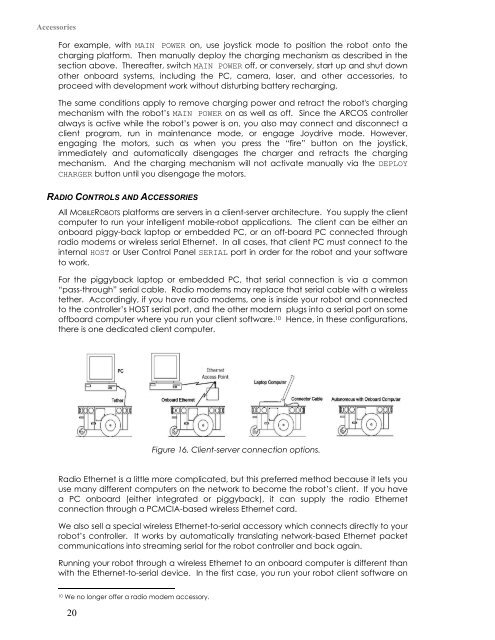
All MOBILEROBOTS platforms are servers in a client-server architecture. You supply the client<br />
computer to run your intelligent mobile-robot applications. The client can be either an<br />
onboard piggy-back laptop or embedded PC, or an off-board PC connected through<br />
radio modems or wireless serial Ethernet. In all cases, that client PC must connect to the<br />
internal HOST or User Control Panel SERIAL port in order for the robot and your software<br />
to work.<br />
For the piggyback laptop or embedded PC, that serial connection is via a common<br />
“pass-through” serial cable. Radio modems may replace that serial cable with a wireless<br />
tether. Accordingly, if you have radio modems, one is inside your robot and connected<br />
to the controller’s HOST serial port, and the other modem plugs into a serial port on some<br />
offboard computer where you run your client software. 10 Hence, in these configurations,<br />
there is one dedicated client computer.<br />
Figure 16. Client-server connection options.<br />
Radio Ethernet is a little more complicated, but this preferred method because it lets you<br />
use many different computers on the network to become the robot’s client. If you have<br />
a PC onboard (either integrated or piggyback), it can supply the radio Ethernet<br />
connection through a PCMCIA-based wireless Ethernet card.<br />
We also sell a special wireless Ethernet-to-serial accessory which connects directly to your<br />
robot’s controller. It works by automatically translating network-based Ethernet packet<br />
communications into streaming serial for the robot controller and back again.<br />
Running your robot through a wireless Ethernet to an onboard computer is different than<br />
with the Ethernet-to-serial device. In the first case, you run your robot client software on<br />
10 We no longer offer a radio modem accessory.<br />
20