Pioneer 3™ Operations Manual
Pioneer 3™ Operations Manual
Pioneer 3™ Operations Manual

You also want an ePaper? Increase the reach of your titles
YUMPU automatically turns print PDFs into web optimized ePapers that Google loves.
Advanced Robot Control & <strong>Operations</strong> Software<br />
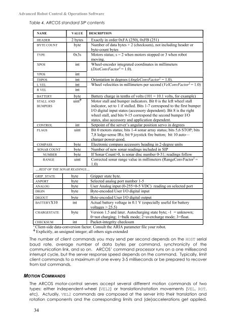
Table 4. ARCOS standard SIP contents<br />
NAME VALUE DESCRIPTION<br />
HEADER 2 bytes Exactly in order 0xFA (250), 0xFB (251)<br />
BYTE COUNT byte Number of data bytes + 2 (checksum), not including header or<br />
byte-count bytes<br />
TYPE 0x3s Motors status; s = 2 when motors stopped or 3 when robot<br />
moving.<br />
XPOS int Wheel-encoder integrated coordinates in millimeters<br />
(DistConvFactor ‡ = 1.0).<br />
YPOS int<br />
THPOS int Orientation in degrees (AngleConvFactor ‡ = 1.0).<br />
L VEL int Wheel velocities in millimeters per second (VelConvFactor ‡ = 1.0)<br />
R VEL int<br />
BATTERY byte Battery charge in tenths of volts (101 = 10.1 volts, for example)<br />
STALL AND<br />
BUMPERS<br />
uint ╪ Motor stall and bumper indicators. Bit 0 is the left wheel stall<br />
indicator, set to 1 if stalled. Bits 1-7 correspond to the first bumper<br />
I/O digital input states (accessory dependent). Bit 8 is the right<br />
wheel stall, and bits 9-15 correspond the second bumper I/O<br />
states, also accessory and application dependent.<br />
CONTROL int Setpoint of the server’s angular position servo in degrees<br />
FLAGS uint Bit 0 motors status; bits 1-4 sonar array status; bits 5,6 STOP; bits<br />
7,8 ledge-sense IRs; bit 9 joystick fire button; bit 10 auto—<br />
charger power-good.<br />
COMPASS byte Electronic compass accessory heading in 2-degree units<br />
SONAR COUNT byte Number of new sonar readings included in SIP<br />
NUMBER byte If Sonar Count>0, is sonar disc number 0-31; readings follow<br />
RANGE uint Corrected sonar range value in millimeters (RangeConvFactor ‡ =<br />
1.0)<br />
…REST OF THE SONAR READINGS…<br />
GRIP_STATE byte Gripper state byte.<br />
ANPORT byte Selected analog port number 1-5<br />
ANALOG byte User Analog input (0-255=0-5 VDC) reading on selected port<br />
DIGIN byte Byte-encoded User I/O digital input<br />
DIGOUT byte Byte-encoded User I/O digital output<br />
BATTERYX10 int Actual battery voltage in 0.1 V (especially useful for battery<br />
voltages > 25.5)<br />
CHARGESTATE byte Version 1.5 and later. Autocharging state byte; -1 = unknown;<br />
0=not charging; 1=bulk mode; 2=overcharge mode; 3=float.<br />
CHECKSUM int Packet-integrity checksum<br />
‡<br />
Client-side data-conversion factor. Consult the ARIA parameter file your robot.<br />
╪<br />
Explicitly, an unsigned integer; all others sign-extended<br />
The number of client commands you may send per second depends on the HOST serial<br />
baud rate, average number of data bytes per command, synchronicity of the<br />
communication link, and so on. ARCOS’ command processor runs on a one millisecond<br />
interrupt cycle, but the server response speed depends on the command. Typically, limit<br />
client commands to a maximum of one every 3-5 milliseconds or be prepared to recover<br />
from lost commands.<br />
MOTION COMMANDS<br />
The ARCOS motor-control servers accept several different motion commands of two<br />
types: either independent-wheel (VEL2) or translation/rotation movements (VEL, ROT,<br />
etc). Actually, VEL2 commands are composed at the server into their translation and<br />
rotation components and the corresponding limits and (de)accelerations get applied.<br />
34