TigerSwitch 10/100 - SMC
TigerSwitch 10/100 - SMC
TigerSwitch 10/100 - SMC

Create successful ePaper yourself
Turn your PDF publications into a flip-book with our unique Google optimized e-Paper software.
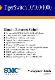
<strong>TigerSwitch</strong> <strong>10</strong>/<strong>10</strong>0<br />
Stackable Fast Ethernet Switch<br />
◆ 12/24 <strong>10</strong>BASE-T/<strong>10</strong>0BASE-TX ports<br />
◆ Optional <strong>10</strong>0BASE-FX or <strong>10</strong>00BASE-SX modules<br />
◆ Optional stack module for linking up to four units<br />
◆ 8.8 Gbps of aggregate switch bandwidth<br />
◆ Support for redundant power unit<br />
◆ Up to five port trunks per switch<br />
◆ Port mirroring for non-intrusive analysis<br />
◆ QoS support for two-level priority<br />
◆ Full support for VLANs with GVRP<br />
◆ IGMP multicast filtering and snooping<br />
◆ Manageable via console, Web, SNMP/RMON<br />
Management Guide<br />
<strong>SMC</strong>6912M<br />
<strong>SMC</strong>6924M
<strong>TigerSwitch</strong> <strong>10</strong>/<strong>10</strong>0<br />
Management Guide<br />
From <strong>SMC</strong>’s Tiger line of feature-rich workgroup LAN solutions<br />
6 Hughes<br />
Irvine, CA 92618<br />
Phone: (949) 707-2400<br />
February 2001<br />
Pub. # F2.42 150073-<strong>10</strong>2 R06
Information furnished by <strong>SMC</strong> Networks, Inc. (<strong>SMC</strong>) is believed to<br />
be accurate and reliable. However, no responsibility is assumed by<br />
<strong>SMC</strong> for its use, nor for any infringements of patents or other rights<br />
of third parties which may result from its use. No license is granted<br />
by implication or otherwise under any patent or patent rights of<br />
<strong>SMC</strong>. <strong>SMC</strong> reserves the right to change specifications at any time<br />
without notice.<br />
Copyright © 2001 by<br />
<strong>SMC</strong> Networks, Inc.<br />
6 Hughes<br />
Irvine, CA 92618<br />
All rights reserved. Printed in Taiwan<br />
Trademarks:<br />
<strong>SMC</strong> is a registered trademark; and EZ Switch, TigerStack and <strong>TigerSwitch</strong> are trademarks of<br />
<strong>SMC</strong> Networks, Inc. Other product and company names are trademarks or registered<br />
trademarks of their respective holders.
Limited Warranty<br />
LIMITED WARRANTY<br />
Limited Warranty Statement: <strong>SMC</strong> Networks, Inc. (“<strong>SMC</strong>”) warrants its products<br />
to be free from defects in workmanship and materials, under normal use and<br />
service, for the applicable warranty term. All <strong>SMC</strong> products carry a standard 90-day<br />
limited warranty from the date of purchase from <strong>SMC</strong> or its Authorized Reseller.<br />
<strong>SMC</strong> may, at its own discretion, repair or replace any product not operating as<br />
warranted with a similar or functionally equivalent product, during the applicable<br />
warranty term. <strong>SMC</strong> will endeavor to repair or replace any product returned under<br />
warranty within 30 days of receipt of the product.<br />
The standard limited warranty can be upgraded to a Limited Lifetime* warranty by<br />
registering new products within 30 days of purchase from <strong>SMC</strong> or its Authorized<br />
Reseller. Registration can be accomplished via the enclosed product registration<br />
card or online via the <strong>SMC</strong> web site. Failure to register will not affect the standard<br />
limited warranty. The Limited Lifetime warranty covers a product during the Life of<br />
that Product, which is defined as the period of time during which the product is an<br />
“Active” <strong>SMC</strong> product. A product is considered to be “Active” while it is listed on<br />
the current <strong>SMC</strong> price list. As new technologies emerge, older technologies become<br />
obsolete and <strong>SMC</strong> will, at its discretion, replace an older product in its product line<br />
with one that incorporates these newer technologies. At that point, the obsolete<br />
product is discontinued and is no longer an “Active” <strong>SMC</strong> product. A list of<br />
discontinued products with their respective dates of discontinuance can be found at<br />
http://www.smc.com/smc/pages_html/support.html.<br />
All products that are replaced become the property of <strong>SMC</strong>. Replacement products<br />
may be either new or reconditioned. Any replaced or repaired product carries<br />
either a 30-day limited warranty or the remainder of the initial warranty, whichever<br />
is longer. <strong>SMC</strong> is not responsible for any custom software or firmware,<br />
configuration information, or memory data of Customer contained in, stored on, or<br />
integrated with any products returned to <strong>SMC</strong> pursuant to any warranty. Products<br />
returned to <strong>SMC</strong> should have any customer-installed accessory or add-on<br />
components, such as expansion modules, removed prior to returning the product<br />
for replacement. <strong>SMC</strong> is not responsible for these items if they are returned with the<br />
product.<br />
Customers must contact <strong>SMC</strong> for a Return Material Authorization number prior to<br />
returning any product to <strong>SMC</strong>. Proof of purchase may be required. Any product<br />
returned to <strong>SMC</strong> without a valid Return Material Authorization (RMA) number<br />
clearly marked on the outside of the package will be returned to customers at<br />
customer’s expense. For warranty claims within North America, please call our<br />
toll-free customer support number at (800) 762-4968. Customers are responsible for<br />
all shipping charges from their facility to <strong>SMC</strong>. <strong>SMC</strong> is responsible for return<br />
shipping charges from <strong>SMC</strong> to customer.<br />
WARRANTIES EXCLUSIVE: IF AN <strong>SMC</strong> PRODUCT DOES NOT OPERATE AS<br />
WARRANTED ABOVE, CUSTOMER’S SOLE REMEDY SHALL BE REPAIR OR<br />
REPLACEMENT OF THE PRODUCT IN QUESTION, AT <strong>SMC</strong>’S OPTION. THE<br />
FOREGOING WARRANTIES AND REMEDIES ARE EXCLUSIVE AND ARE IN LIEU
LIMITED WARRANTY<br />
OF ALL OTHER WARRANTIES OR CONDITIONS, EXPRESS OR IMPLIED, EITHER<br />
IN FACT OR BY OPERATION OF LAW, STATUTORY OR OTHERWISE, INCLUDING<br />
WARRANTIES OR CONDITIONS OF MERCHANTABILITY AND FITNESS FOR A<br />
PARTICULAR PURPOSE. <strong>SMC</strong> NEITHER ASSUMES NOR AUTHORIZES ANY OTHER<br />
PERSON TO ASSUME FOR IT ANY OTHER LIABILITY IN CONNECTION WITH<br />
THE SALE, INSTALLATION, MAINTENANCE OR USE OF ITS PRODUCTS. <strong>SMC</strong><br />
SHALL NOT BE LIABLE UNDER THIS WARRANTY IF ITS TESTING AND<br />
EXAMINATION DISCLOSE THE ALLEGED DEFECT IN THE PRODUCT DOES NOT<br />
EXIST OR WAS CAUSED BY CUSTOMER’S OR ANY THIRD PERSON’S MISUSE,<br />
NEGLECT, IMPROPER INSTALLATION OR TESTING, UNAUTHORIZED ATTEMPTS<br />
TO REPAIR, OR ANY OTHER CAUSE BEYOND THE RANGE OF THE INTENDED<br />
USE, OR BY ACCIDENT, FIRE, LIGHTNING, OR OTHER HAZARD.<br />
LIMITATION OF LIABILITY: IN NO EVENT, WHETHER BASED IN CONTRACT OR<br />
TORT (INCLUDING NEGLIGENCE), SHALL <strong>SMC</strong> BE LIABLE FOR INCIDENTAL,<br />
CONSEQUENTIAL, INDIRECT, SPECIAL, OR PUNITIVE DAMAGES OF ANY KIND,<br />
OR FOR LOSS OF REVENUE, LOSS OF BUSINESS, OR OTHER FINANCIAL LOSS<br />
ARISING OUT OF OR IN CONNECTION WITH THE SALE, INSTALLATION,<br />
MAINTENANCE, USE, PERFORMANCE, FAILURE, OR INTERRUPTION OF ITS<br />
PRODUCTS, EVEN IF <strong>SMC</strong> OR ITS AUTHORIZED RESELLER HAS BEEN ADVISED<br />
OF THE POSSIBILITY OF SUCH DAMAGES.<br />
SOME STATES DO NOT ALLOW THE EXCLUSION OF IMPLIED WARRANTIES OR<br />
THE LIMITATION OF INCIDENTAL OR CONSEQUENTIAL DAMAGES FOR<br />
CONSUMER PRODUCTS, SO THE ABOVE LIMITATIONS AND EXCLUSIONS MAY<br />
NOT APPLY TO YOU. THIS WARRANTY GIVES YOU SPECIFIC LEGAL RIGHTS,<br />
WHICH MAY VARY FROM STATE TO STATE. NOTHING IN THIS WARRANTY<br />
SHALL BE TAKEN TO AFFECT YOUR STATUTORY RIGHTS.<br />
* <strong>SMC</strong> will provide warranty service for one year following discontinuance from the<br />
active <strong>SMC</strong> price list. Under the limited lifetime warranty, internal and external<br />
power supplies, fans, and cables are covered by a standard one-year warranty from<br />
date of purchase.<br />
<strong>SMC</strong> Networks, Inc.<br />
6 Hughes<br />
Irvine, CA 92618
TABLE OF CONTENTS<br />
1 Switch Management . . . . . . . . . . . . . . . . . . . . . . 1-1<br />
Configuration Options . . . . . . . . . . . . . . . . . . . . . . . . . . . . . . 1-1<br />
Required Connections . . . . . . . . . . . . . . . . . . . . . . . . . . . . . . 1-2<br />
Console Port (Out-of-Band) Connections . . . . . . . . . . . . 1-2<br />
Remote Management via the Console Port . . . . . . . . . . . 1-3<br />
Configure the Switch Site . . . . . . . . . . . . . . . . . . . . 1-3<br />
Configure the Remote Site . . . . . . . . . . . . . . . . . . . 1-3<br />
In-Band Connections . . . . . . . . . . . . . . . . . . . . . . . . . . 1-4<br />
2 Using the System Configuration Program . . . . . 2-1<br />
Login Screen . . . . . . . . . . . . . . . . . . . . . . . . . . . . . . . . . . . . . 2-1<br />
Main Menu . . . . . . . . . . . . . . . . . . . . . . . . . . . . . . . . . . . . . . 2-3<br />
System Information Menu . . . . . . . . . . . . . . . . . . . . . . . . . . . 2-6<br />
Displaying System Information . . . . . . . . . . . . . . . . . . . 2-7<br />
Displaying Switch Version Information . . . . . . . . . . . . . 2-8<br />
Management Setup Menu . . . . . . . . . . . . . . . . . . . . . . . . . . . 2-<strong>10</strong><br />
Changing the Network Configuration . . . . . . . . . . . . . 2-11<br />
IP Configuration . . . . . . . . . . . . . . . . . . . . . . . . . . 2-12<br />
IP Connectivity Test (Ping) . . . . . . . . . . . . . . . . . . 2-14<br />
HTTP Configuration . . . . . . . . . . . . . . . . . . . . . . . 2-15<br />
Configuring the Serial Port . . . . . . . . . . . . . . . . . . . . . 2-16<br />
Assigning SNMP Parameters . . . . . . . . . . . . . . . . . . . . 2-18<br />
Configuring Community Names . . . . . . . . . . . . . . 2-19<br />
Configuring IP Trap Managers . . . . . . . . . . . . . . . 2-20<br />
Console Login Configuration . . . . . . . . . . . . . . . . . . . . 2-21<br />
Downloading System Software . . . . . . . . . . . . . . . . . . 2-23<br />
Using TFTP to Download Over the Network . . . . . 2-23<br />
Saving the System Configuration . . . . . . . . . . . . . . . . . 2-24<br />
Configuring the Switch . . . . . . . . . . . . . . . . . . . . . . . . . . . . . 2-26<br />
Configuring Port Parameters . . . . . . . . . . . . . . . . . . . . 2-28<br />
Viewing the Current Port Configuration . . . . . . . . . . . . 2-29<br />
Using the Spanning Tree Algorithm . . . . . . . . . . . . . . . 2-30<br />
Configuring Bridge STA . . . . . . . . . . . . . . . . . . . . 2-31<br />
Configuring STA for Ports . . . . . . . . . . . . . . . . . . . 2-33<br />
Viewing the Current Spanning Tree Information . . . . . 2-34<br />
Displaying the Current Bridge STA . . . . . . . . . . . . 2-35<br />
i
TABLE OF CONTENTS<br />
ii<br />
Displaying the Current STA for Ports . . . . . . . . . . 2-36<br />
Using a Mirror Port for Analysis . . . . . . . . . . . . . . . . . 2-38<br />
Configuring Port Trunks . . . . . . . . . . . . . . . . . . . . . . 2-39<br />
IGMP Multicast Filtering . . . . . . . . . . . . . . . . . . . . . . . 2-42<br />
Configuring IGMP . . . . . . . . . . . . . . . . . . . . . . . . 2-43<br />
Configuring Broadcast Storm Control . . . . . . . . . . . . . 2-44<br />
Configuring Bridge MIB Extensions . . . . . . . . . . . . . . 2-45<br />
Configuring Traffic Classes . . . . . . . . . . . . . . . . . . . . . 2-47<br />
Port Priority Configuration . . . . . . . . . . . . . . . . . . 2-48<br />
802.1p Port Traffic Class Information . . . . . . . . . . 2-49<br />
Configuring Virtual LANs . . . . . . . . . . . . . . . . . . . . . 2-50<br />
802.1Q VLAN Base Information . . . . . . . . . . . . . . 2-50<br />
802.1Q VLAN Current Table Information . . . . . . . 2-51<br />
802.1Q VLAN Static Table Configuration . . . . . . . . 2-53<br />
802.1Q VLAN Port Configuration . . . . . . . . . . . . . 2-55<br />
Port Security Configuration . . . . . . . . . . . . . . . . . . . . 2-57<br />
Monitoring the Switch . . . . . . . . . . . . . . . . . . . . . . . . . . . . . 2-59<br />
Displaying Port Statistics . . . . . . . . . . . . . . . . . . . . . . 2-60<br />
Displaying RMON Statistics . . . . . . . . . . . . . . . . . . . . 2-62<br />
Displaying the Unicast Address Table . . . . . . . . . . . . . 2-64<br />
Displaying the IP Multicast Registration Table . . . . . . . 2-66<br />
Configuring Static Unicast Addresses . . . . . . . . . . . . . 2-67<br />
Resetting the System . . . . . . . . . . . . . . . . . . . . . . . . . . . . . . 2-69<br />
Logging Off the System . . . . . . . . . . . . . . . . . . . . . . . . . . . . 2-69<br />
3 Web-Based Management . . . . . . . . . . . . . . . . . . . 3-1<br />
Web-Based Configuration and Monitoring . . . . . . . . . . . . . . . 3-1<br />
Navigating the Web Browser Interface . . . . . . . . . . . . . . . . . . 3-2<br />
Home Page . . . . . . . . . . . . . . . . . . . . . . . . . . . . . . . . . 3-2<br />
Configuration Options . . . . . . . . . . . . . . . . . . . . . . . . . 3-3<br />
Panel Display . . . . . . . . . . . . . . . . . . . . . . . . . . . . . . . . . . . . 3-4<br />
Port State Display . . . . . . . . . . . . . . . . . . . . . . . . . . . . 3-4<br />
Console Configuration . . . . . . . . . . . . . . . . . . . . . . . . . 3-5<br />
Main Menu . . . . . . . . . . . . . . . . . . . . . . . . . . . . . . . . . . . . . . 3-7<br />
System Information . . . . . . . . . . . . . . . . . . . . . . . . . . . . . . . 3-8<br />
Switch Information . . . . . . . . . . . . . . . . . . . . . . . . . . . . . . . 3-9<br />
Main Board . . . . . . . . . . . . . . . . . . . . . . . . . . . . . . . . . 3-9
TABLE OF CONTENTS<br />
Agent Module . . . . . . . . . . . . . . . . . . . . . . . . . . . . . . 3-<strong>10</strong><br />
Expansion Slot . . . . . . . . . . . . . . . . . . . . . . . . . . . . . . 3-<strong>10</strong><br />
IP Configuration . . . . . . . . . . . . . . . . . . . . . . . . . . . . . . . . . 3-11<br />
SNMP Configuration . . . . . . . . . . . . . . . . . . . . . . . . . . . . . . 3-13<br />
SNMP Community . . . . . . . . . . . . . . . . . . . . . . . . . . . 3-13<br />
Trap Managers . . . . . . . . . . . . . . . . . . . . . . . . . . . . . . 3-14<br />
Security Configuration . . . . . . . . . . . . . . . . . . . . . . . . . . . . . 3-15<br />
Change Password . . . . . . . . . . . . . . . . . . . . . . . . . . . . 3-15<br />
Firmware Upgrade Options . . . . . . . . . . . . . . . . . . . . . . . . . 3-16<br />
Web Upload Management . . . . . . . . . . . . . . . . . . . . . 3-16<br />
TFTP Download Management . . . . . . . . . . . . . . . . . . . 3-17<br />
Configuration Save and Restore . . . . . . . . . . . . . . . . . . . . . . 3-18<br />
Configuration Upload Management . . . . . . . . . . . . . . . 3-18<br />
Configuration Download Management . . . . . . . . . . . . 3-19<br />
Address Table Configuration . . . . . . . . . . . . . . . . . . . . . . . . 3-20<br />
Spanning Tree Algorithm (STA) . . . . . . . . . . . . . . . . . . . . . . 3-21<br />
Spanning Tree Information . . . . . . . . . . . . . . . . . . . . . 3-21<br />
Spanning Tree . . . . . . . . . . . . . . . . . . . . . . . . . . . 3-22<br />
Ports . . . . . . . . . . . . . . . . . . . . . . . . . . . . . . . . . . 3-23<br />
Spanning Tree Configuration . . . . . . . . . . . . . . . . . . . 3-25<br />
Switch . . . . . . . . . . . . . . . . . . . . . . . . . . . . . . . . . 3-25<br />
When the Switch Becomes Root . . . . . . . . . . . . . . 3-25<br />
STA Port Configuration . . . . . . . . . . . . . . . . . . . . . . . . 3-27<br />
Configuring Bridge MIB Extensions . . . . . . . . . . . . . . . . . . . 3-29<br />
Bridge Capability . . . . . . . . . . . . . . . . . . . . . . . . . . . . 3-29<br />
Bridge Settings . . . . . . . . . . . . . . . . . . . . . . . . . . . . . . 3-30<br />
Priority . . . . . . . . . . . . . . . . . . . . . . . . . . . . . . . . . . . . . . . . 3-31<br />
Port Priority Configuration . . . . . . . . . . . . . . . . . . . . . 3-31<br />
Port Traffic Class Information . . . . . . . . . . . . . . . . . . . 3-32<br />
Configuring Virtual LANs . . . . . . . . . . . . . . . . . . . . . . . . . . 3-33<br />
VLAN Basic Information . . . . . . . . . . . . . . . . . . . . . . . 3-33<br />
VLAN Current Table . . . . . . . . . . . . . . . . . . . . . . . . . . 3-34<br />
VLAN Static List . . . . . . . . . . . . . . . . . . . . . . . . . . . . . 3-35<br />
VLAN Static Table . . . . . . . . . . . . . . . . . . . . . . . . . . . . 3-36<br />
VLAN Static Membership by Port . . . . . . . . . . . . . . . . . 3-38<br />
VLAN Port Configuration . . . . . . . . . . . . . . . . . . . . . . 3-39<br />
IGMP Multicast Filtering . . . . . . . . . . . . . . . . . . . . . . . . . . . . 3-40<br />
iii
TABLE OF CONTENTS<br />
iv<br />
Configuring IGMP . . . . . . . . . . . . . . . . . . . . . . . . . . . 3-41<br />
IP Multicast Registration Table . . . . . . . . . . . . . . . . . 3-42<br />
Port Menus . . . . . . . . . . . . . . . . . . . . . . . . . . . . . . . . . . . . . 3-43<br />
Port Information . . . . . . . . . . . . . . . . . . . . . . . . . . . . 3-43<br />
Port Configuration . . . . . . . . . . . . . . . . . . . . . . . . . . . 3-44<br />
Port Broadcast Storm Protect Configuration . . . . . . . . 3-46<br />
Port Security Configuration . . . . . . . . . . . . . . . . . . . . 3-47<br />
Using a Port Mirror for Analysis . . . . . . . . . . . . . . . . . . . . . . 3-48<br />
Port Trunk Configuration . . . . . . . . . . . . . . . . . . . . . . . . . . 3-49<br />
Port Statistics . . . . . . . . . . . . . . . . . . . . . . . . . . . . . . . . . . . 3-52<br />
Etherlike Statistics . . . . . . . . . . . . . . . . . . . . . . . . . . . 3-52<br />
RMON Statistics . . . . . . . . . . . . . . . . . . . . . . . . . . . . . 3-54<br />
4 Advanced Topics . . . . . . . . . . . . . . . . . . . . . . . . . 4-1<br />
Layer 2 Switching . . . . . . . . . . . . . . . . . . . . . . . . . . . . . . . . . 4-1<br />
Spanning Tree Algorithm . . . . . . . . . . . . . . . . . . . . . . . 4-2<br />
Virtual LANs . . . . . . . . . . . . . . . . . . . . . . . . . . . . . . . . . . . . . 4-3<br />
Assigning Ports to VLANs . . . . . . . . . . . . . . . . . . . . . . . 4-4<br />
Port Overlapping . . . . . . . . . . . . . . . . . . . . . . . . . . 4-5<br />
Automatic VLAN Registration (GVRP) . . . . . . . . . . . . . . 4-5<br />
Forwarding Traffic with Unknown VLAN Tags . . . . 4-6<br />
Forwarding Tagged/Untagged Frames . . . . . . . . . . . . . 4-6<br />
Connecting VLAN Groups . . . . . . . . . . . . . . . . . . . . . . 4-7<br />
Multicast Filtering . . . . . . . . . . . . . . . . . . . . . . . . . . . . . . . . . 4-7<br />
IGMP Snooping . . . . . . . . . . . . . . . . . . . . . . . . . . . . . . 4-7<br />
IGMP Protocol . . . . . . . . . . . . . . . . . . . . . . . . . . . . . . . 4-8<br />
Class-of-Service (CoS) Support . . . . . . . . . . . . . . . . . . . . . . . 4-9<br />
Port Trunks . . . . . . . . . . . . . . . . . . . . . . . . . . . . . . . . . . . . . 4-9<br />
SNMP Management Software . . . . . . . . . . . . . . . . . . . . . . . . 4-<strong>10</strong><br />
Remote Monitoring . . . . . . . . . . . . . . . . . . . . . . . . . . . . . . . 4-<strong>10</strong><br />
A Troubleshooting . . . . . . . . . . . . . . . . . . . . . . . . . .A-1<br />
Troubleshooting Chart . . . . . . . . . . . . . . . . . . . . . . . . . . . . . A-1<br />
Upgrading Firmware via the Serial Port . . . . . . . . . . . . . . . . . A-2
TABLE OF CONTENTS<br />
B Pin Assignments . . . . . . . . . . . . . . . . . . . . . . . . . B-1<br />
Console Port Pin Assignments . . . . . . . . . . . . . . . . . . . . . . . .B-1<br />
DB-9 Port Pin Assignments . . . . . . . . . . . . . . . . . . . . . .B-2<br />
Console Port to 9-Pin COM Port on PC . . . . . . . . . . . . .B-2<br />
Console Port to 25-Pin DCE Port on Modem . . . . . . . . .B-2<br />
Console Port to 25-Pin DTE Port on PC . . . . . . . . . . . . .B-3<br />
Glossary<br />
Index<br />
v
TABLE OF CONTENTS<br />
vi
Configuration Options<br />
CHAPTER 1<br />
SWITCH MANAGEMENT<br />
For advanced management capability, the <strong>TigerSwitch</strong> <strong>10</strong>/<strong>10</strong>0<br />
management agent provides a menu-driven system configuration<br />
program. This program can be accessed by a direct or modem<br />
connection to the serial port on the rear panel (out-of-band), or by<br />
a Telnet connection over the network (in-band).<br />
The management agent is based on SNMP (Simple Network<br />
Management Protocol). This SNMP agent permits the switch to be<br />
managed from any PC in the network using in-band management<br />
software (such as <strong>SMC</strong>’s EliteView).<br />
The management agent also includes an embedded HTTP Web<br />
agent. This Web agent can be accessed using a standard Web<br />
browser from any computer attached to the network.<br />
The system configuration program and the SNMP agent support<br />
management functions such as:<br />
Enable/disable any port<br />
Set the communication mode for any port<br />
Configure SNMP parameters<br />
Configure VLANs or multicast filtering<br />
Display system information or statistics<br />
Configure the switch to join a Spanning Tree<br />
Download system firmware<br />
Restart the system<br />
1-1
SWITCH MANAGEMENT<br />
Required Connections<br />
Console Port (Out-of-Band) Connections<br />
1-2<br />
Attach a VT<strong>10</strong>0 compatible terminal or a PC running a terminal<br />
emulation program to the serial port on the switch’s rear panel.<br />
Use the null-modem cable provided with this package, or use a<br />
null modem connection that complies with the wiring assignments<br />
shown in Appendix B of this guide.<br />
When attaching to a PC, set terminal emulation type to VT<strong>10</strong>0,<br />
specify the port used by your PC (i.e., COM 1~4), and then set<br />
communications to 8 data bits, 1 stop bit, no parity, and 19200 bps<br />
(for initial configuration). Also be sure to set flow control to<br />
“none.” (Refer to “Configuring the Serial Port” on page 2-16 for a<br />
complete description of configuration options.)<br />
Note: If the default settings for the management agent’s serial port<br />
have been modified and you are having difficulty making a<br />
console connection, you can display or modify the current<br />
settings using a Web browser as described under “Console<br />
Configuration” on page 3-5.
Remote Management via the Console Port<br />
SWITCH MANAGEMENT<br />
Configure the Switch Site<br />
Connect the switch’s DB9 serial port to the modem’s serial port<br />
using standard cabling. For most modems which use a 25-pin port,<br />
you will have to provide an RS-232 cable with a 9-pin connector on<br />
one end and a 25-pin connector on the other end. Set the modem<br />
at the switch’s site to force auto-answer mode. The following is a<br />
sample initialization string: “ATQ1S0=1&D0&K0&W” as defined<br />
below:<br />
Q1 : Inhibit result codes to DTE<br />
S0=1 : Auto answer on first ring<br />
D0 : Don’t care DTR<br />
K0 : Disables DTE/DCE flow control<br />
W : Write command to modem memory<br />
Configure the Remote Site<br />
At the remote site, connect the PC’s COM port (COM 1~4) to the<br />
modem’s serial port. Set terminal emulation type to VT<strong>10</strong>0, specify<br />
the port used by your PC (i.e., COM 1~4), and then set<br />
communications to 8 data bits, 1 stop bit, no parity, 19200 bps and<br />
no flow control.<br />
1-3
SWITCH MANAGEMENT<br />
In-Band Connections<br />
1-4<br />
Prior to accessing the Network Management Module via a network<br />
connection, you must first configure it with a valid IP address,<br />
subnet mask, and default gateway using an out-of-band<br />
connection or the BOOTP protocol.<br />
After configuring the switch’s IP parameters, you can access the<br />
on-board configuration program from anywhere within the<br />
attached network. The on-board configuration program can be<br />
accessed using Telnet from any computer attached to the network.<br />
The switch and stack can also be managed by any computer using<br />
a Web browser (Internet Explorer 4.0, or Netscape Navigator 4.0 or<br />
above), or from a network computer using network management<br />
software such as EliteView.<br />
Notes: 1. By default BOOTP is disabled. To enable BOOTP, see<br />
“IP Configuration” on page 2-12.<br />
2. Use the Network Configuration menu to specify the<br />
maximum number of simultaneous Telnet sessions that<br />
are supported by the system (up to four).<br />
3. The on-board program only provides access to basic<br />
configuration functions. To access the full range of<br />
SNMP management functions, you must use SNMP-<br />
based network management software, such as <strong>SMC</strong>’s<br />
free EliteView software.
CHAPTER 2<br />
USING THE SYSTEM<br />
CONFIGURATION PROGRAM<br />
Login Screen<br />
Once a direct connection to the serial port or a Telnet connection<br />
is established, the login screen for the on-board configuration<br />
program appears as shown below.<br />
SSSSSSSSSSSSSSS MMMMM MMMMM CCCCCCCCCCCCCC<br />
SSSSSSSSSSSSSSSSS MM MM CCCCCCCCCCCCCCCC<br />
SS S MMM MMM CCC CC<br />
SS MMMM MMMM CCC<br />
SSSSSSSSSSSSSSSS MM MM MM MM CCC<br />
SS MM MM MM MM CCC CC<br />
S SS MM MM MM MM CCC CC<br />
SSSSSSSSSSSSSSSSS MM MMM MM CCCCCCCCCCCCCCCC<br />
SSSSSSSSSSSSSSS MMMM MMMMM MMMM CCCCCCCCCCCCCC<br />
<strong>TigerSwitch</strong> <strong>10</strong>/<strong>10</strong>0 <strong>SMC</strong>6912M/6924M<br />
V2.42 12-13-2000 (c)Copyright 2000, <strong>SMC</strong> Networks Inc.<br />
User name :<br />
Password :<br />
If this is your first time to log into the configuration program, then<br />
the default user names are “admin” and “guest,” with no password.<br />
The administrator has Read/Write access to all configuration<br />
parameters and statistics. While the guest has Read Only access to<br />
the management program.<br />
2-1
USING THE SYSTEM CONFIGURATION PROGRAM<br />
2-2<br />
You should define a new administrator password, record it and put<br />
it in a safe place. Select Console Login Configuration from the<br />
Management Setup Menu and enter a new password for the<br />
administrator. Note that passwords can consist of up to 11<br />
alphanumeric characters and are not case sensitive.<br />
Note: Based on the default configuration, a user is allowed three<br />
attempts to enter the correct password; on the third failed<br />
attempt the current connection is terminated.<br />
After you enter the user name and password, you will have access<br />
to the system configuration program as illustrated by the following<br />
menu hierarchy:<br />
System<br />
Information Menu<br />
Management<br />
Setup Menu<br />
Device<br />
Control Menu<br />
Network<br />
Monitor Menu<br />
System<br />
Restart Menu<br />
Exit<br />
System Information<br />
Switch Information<br />
Network Configuration<br />
Serial Port Configuration<br />
SNMP Configuration<br />
Console Login Configuration<br />
TFTP Download<br />
Configuration Save & Restore<br />
Port Configuration<br />
Port Information<br />
Spanning Tree Configuration<br />
Spanning Tree Information<br />
Mirror Port Configuration<br />
Port Trunking Configuration<br />
IGMP Configuration<br />
BStorm Control Configuration<br />
Extented Bridge Configuration<br />
802.1P Configuration<br />
802.1Q VLAN Base Information<br />
802.1Q VLAN Current Table Information<br />
802.1Q VLAN Static Table Configuration<br />
802.1Q VLAN Port Configuration<br />
Port Security Configuration<br />
Port GARP Configuration*<br />
Port GMRP Configuration*<br />
Port Statistics<br />
RMON Statistics<br />
Unicast Address Table<br />
Multicast Address Registration Table*<br />
IP Multicast Registration Table<br />
Static Unicast Address Table Configuration<br />
Static Multicast Address Table Configuration*<br />
* Not implemented in this firmware release.<br />
IP Configuration<br />
IP Connectivity Test(Ping)<br />
HTTP Configuration<br />
SNMP Communities<br />
IP Trap Managers<br />
STA Bridge Configuration<br />
STA Port Configuration<br />
STA Bridge Information<br />
STA Port Information<br />
802.1P Port Priority Configuration<br />
802.1P Port Traffic Class Information
Main Menu<br />
USING THE SYSTEM CONFIGURATION PROGRAM<br />
With the system configuration program you can define system<br />
parameters, manage and control the switch, the connected stack<br />
and all its ports, or monitor network conditions. The figure below<br />
of the Main Menu and the following table briefly describe the<br />
selections available from this program.<br />
Note: Options for the currently selected item are displayed in the<br />
highlighted area at the bottom of the interface screen.<br />
Main Menu<br />
=========<br />
System Information Menu...<br />
Management Setup Menu...<br />
Device Control Menu...<br />
Network Monitor Menu...<br />
Restart System Menu...<br />
Exit<br />
Use or arrow keys to move. to select.<br />
Menu Description<br />
System Information Menu<br />
System Information Provides basic system description, including<br />
contact information.<br />
Switch Information Shows hardware/firmware version numbers,<br />
power status, and expansion modules used in<br />
the stack.<br />
2-3
USING THE SYSTEM CONFIGURATION PROGRAM<br />
2-4<br />
Menu Description<br />
Management Setup Menu<br />
Network Configuration Includes IP setup, Ping facility, HTTP (Web<br />
agent) setup, Telnet configuration, and MAC<br />
address.<br />
Serial Port Configuration Sets communication parameters for the serial<br />
port, including management mode, baud rate,<br />
console time-out, and screen data refresh<br />
interval.<br />
SNMP Configuration Activates traps; and configures communities<br />
and trap managers.<br />
Console Login<br />
Configuration<br />
Sets user names and passwords for system<br />
access, as well as the invalid password<br />
threshold and lockout time.<br />
TFTP Download Downloads new version of firmware to update<br />
your system (in-band).<br />
Configuration Save<br />
& Restore<br />
Saves the switch configuration to a file on a<br />
TFTP server. This file can be later downloaded<br />
to restore the configuration.<br />
Device Control Menu<br />
Port Configuration Enables any port, enables/disables flow<br />
control, and sets communication mode to<br />
auto-negotiation, full duplex or half duplex.<br />
Port Information Displays operational status, including link<br />
state, flow control method, and duplex mode.<br />
Spanning Tree<br />
Configuration<br />
Spanning Tree<br />
Information<br />
Enables Spanning Tree Algorithm; also sets<br />
parameters for hello time, maximum message<br />
age, switch priority, and forward delay; as well<br />
as port priority, path cost, and fast forwarding.<br />
Displays full listing of parameters for the<br />
Spanning Tree Algorithm.<br />
Port Mirror Configuration Sets the source and target ports for mirroring.<br />
Port Trunking<br />
Specifies ports to group into aggregate trunks.<br />
Configuration<br />
IGMP Configuration Configures IGMP multicast filtering.<br />
BStorm Control<br />
Allows you to enable/disable broadcast<br />
Configuration<br />
storm control on a per-port basis and set the<br />
packet-per-second threshold.
Menu Description<br />
Extended Bridge<br />
Configuration<br />
USING THE SYSTEM CONFIGURATION PROGRAM<br />
Displays/configures extended bridge<br />
capabilities provided by this switch.<br />
802.1P Configuration Configures default port priorities and queue<br />
assignments.<br />
802.1Q VLAN<br />
Base Information<br />
802.1Q VLAN Current<br />
Table Information<br />
802.1Q VLAN Static Table<br />
Configuration<br />
802.1Q VLAN<br />
Port Configuration<br />
Port Security<br />
Configuration<br />
Displays basic VLAN information, such as<br />
VLAN version number and maximum VLANs<br />
supported.<br />
Displays VLAN groups and port members.<br />
Configures VLAN groups via static<br />
assignments, including setting port members,<br />
or restricting ports from being dynamically<br />
added to a port by the GVRP protocol.<br />
Displays/configures port-specific VLAN<br />
settings, including PVID, ingress filtering, and<br />
GVRP.<br />
Allows you to enable and configure port<br />
security for the switch.<br />
Port GARP Configuration* Configures settings used in multicast filtering.<br />
Port GMRP Configuration* Configures GMRP multicast filtering.<br />
Network Monitor Menu<br />
Port Statistics Displays statistics on network traffic passing<br />
through the selected port.<br />
RMON Statistics Displays detailed statistical information for the<br />
selected port such as packet type and frame<br />
size counters.<br />
Unicast Address Table Provides full listing for unicast addresses, as<br />
well as search and clear functions.<br />
Multicast Address Provides full listing for multicast addresses, as<br />
Registration Table* well as search and clear functions.<br />
IP Multicast Registration Displays all the multicast groups active on this<br />
Table<br />
switch, including multicast IP addresses and<br />
corresponding VLAN IDs.<br />
Static Unicast Address Used to manually configure host MAC<br />
Table Configuration addresses in the unicast table.<br />
2-5
USING THE SYSTEM CONFIGURATION PROGRAM<br />
System Information Menu<br />
2-6<br />
Menu Description<br />
Static Multicast Address<br />
Table Configuration*<br />
Used to manually configure host MAC<br />
addresses in the multicast table.<br />
Restart System Restarts system with options to use POST, or<br />
to retain factory defaults, IP settings, or user<br />
authentication settings.<br />
Exit Exits the configuration program.<br />
* Not implemented in this firmware release.<br />
Use the System Information Menu to display a basic description of<br />
the switch, including contact information, and hardware/firmware<br />
versions.<br />
System Information Menu<br />
=======================<br />
System Information ...<br />
Switch Information ...<br />
<br />
Use or arrow keys to move. to select<br />
Menu Description<br />
System Information Provides basic system description, including<br />
contact information.<br />
Switch Information Shows hardware/firmware version numbers,<br />
power status, and expansion modules used<br />
in the stack.
Displaying System Information<br />
USING THE SYSTEM CONFIGURATION PROGRAM<br />
Use the System Information screen to display descriptive<br />
information about the switch, or for quick system identification as<br />
shown in the following figure and table.<br />
System Information<br />
==================<br />
System Description : <strong>TigerSwitch</strong> <strong>10</strong>/<strong>10</strong>0 <strong>SMC</strong>6912M/6924M<br />
System Object ID : 1.3.6.1.4.1.202.20.6<br />
System Up Time : 48067 (0 day, 1 hr, 2min, 34 sec)<br />
System Name : DEFAULT SYSTEM NAME<br />
System Contact : DEFAULT SYSTEM CONTACT<br />
System Location : DEFAULT SYSTEM LOCATION<br />
<br />
Use or arrow keys to move, other keys to make changes.<br />
Parameter Description<br />
System Description System hardware description.<br />
System Object ID MIB II object identifier for switch’s network<br />
management subsystem.<br />
System Up Time Length of time the current management<br />
agent has been running. (Note that the first<br />
value is 1/<strong>10</strong>0 seconds.)<br />
System Name* Name assigned to the switch system.<br />
System Contact* Contact person for the system.<br />
System Location* Specifies the area or location where the<br />
system resides.<br />
* Maximum string length is 255, but the screen only displays 45 characters.<br />
You can use the arrow keys to browse the whole string.<br />
2-7
USING THE SYSTEM CONFIGURATION PROGRAM<br />
Displaying Switch Version Information<br />
2-8<br />
Use the Switch Information screen to display hardware/firmware<br />
version numbers for the main board, as well as the power status.<br />
Switch Information : Unit 1<br />
==================<br />
Main Board<br />
Hardware Version : V3.0<br />
Firmware Version : V1.11<br />
Serial Number : 00-CB-00-00-00-00<br />
Port Number : 24<br />
Internal Power Status : Active<br />
Redundant Power Status : Inactive<br />
Expansion Slot 1 : ---------------------<br />
Expansion Slot 2 : ---------------------<br />
Agent Module<br />
Hardware Version : V3.0 (801 CPU)<br />
POST ROM Version : V1.<strong>10</strong><br />
Firmware Version : V2.42<br />
SNMP Agent : Master<br />
<br />
Use or arrow keys to move. to select<br />
Parameter<br />
Main Board<br />
Description<br />
Hardware Version Hardware version of the main board.<br />
Firmware Version System firmware version in ROM.<br />
Serial Number The serial number of the main board.<br />
Port Number Number of ports (including modules).<br />
Internal Power Status Indicates if the primary power is active or<br />
inactive.<br />
Redundant Power Status Indicates if the redundant power is active or<br />
inactive.<br />
Expansion Slot 1 Shows module type if inserted<br />
(<strong>10</strong>0BASE-FX or <strong>10</strong>00BASE-SX).<br />
Expansion Slot 2 Shows module type if inserted<br />
(<strong>10</strong>0BASE-FX or <strong>10</strong>00BASE-SX or 4GB Stack).
Parameter Description<br />
USING THE SYSTEM CONFIGURATION PROGRAM<br />
Agent Module<br />
Hardware Version Hardware version of the agent module.<br />
POST ROM Version Power-On Self-Test version number.<br />
Firmware Version Firmware version of the agent module.<br />
SNMP Agent Shows that the agent module is operating as<br />
Master.<br />
2-9
USING THE SYSTEM CONFIGURATION PROGRAM<br />
Management Setup Menu<br />
2-<strong>10</strong><br />
After initially logging onto the system, adjust the communication<br />
parameters for your console to ensure a reliable connection (Serial<br />
Port Configuration). Specify the IP addresses for the switch<br />
(Network Configuration / IP Configuration), and then set the<br />
Administrator and User passwords (Console Login Configuration).<br />
Remember to record them in a safe place. Also set the community<br />
string which controls access to the on-board SNMP agent via<br />
in-band management software (SNMP Configuration). The items<br />
provided by the Management Setup Menu are described in the<br />
following sections.<br />
Management Setup Menu<br />
=====================<br />
Network Configuration ...<br />
Serial Port Configuration ...<br />
SNMP Configuration ...<br />
Console Login Configuration ...<br />
TFTP Download ...<br />
Configuration Save & Restore ...<br />
<br />
Use or arrow keys to move. to select.<br />
Menu Description<br />
Network Configuration Includes IP setup, Ping facility, HTTP (Web<br />
agent) setup, Telnet configuration, and MAC<br />
address.<br />
Serial Port Configuration Sets communication parameters for the serial<br />
port, including management mode, baud<br />
rate, console time-out, and screen data<br />
refresh interval.<br />
SNMP Configuration Activates traps; and configures communities<br />
and trap managers.
Menu Description<br />
Console Login<br />
Configuration<br />
Changing the Network Configuration<br />
USING THE SYSTEM CONFIGURATION PROGRAM<br />
Sets user names and passwords for system<br />
access, as well as the invalid password<br />
threshold and lockout time.<br />
TFTP Download Downloads new version of firmware to<br />
update your system (in-band).<br />
Configuration Save<br />
& Restore<br />
Saves the switch configuration to a file on a<br />
TFTP server. This file can be later<br />
downloaded to restore the configuration.<br />
Use the Network Configuration menu to set the bootup option,<br />
configure the switch’s Internet Protocol (IP) parameters, enable the<br />
on-board Web agent, or to set the number of concurrent Telnet<br />
sessions allowed. The screen shown below is described in the<br />
following table.<br />
Network Configuration<br />
=====================<br />
IP Configuration ...<br />
IP Connectivity Test (Ping) ...<br />
HTTP Configuration ...<br />
MAX Number of allowed Telnet sessions (1 -4) : 4<br />
MAC Address : 00-E0-29-52-28-00<br />
<br />
Use or arrow keys to move. to select.<br />
Parameter Description<br />
IP Configuration Screen used to set the bootup option, or<br />
configure the switch’s IP parameters.<br />
IP Connectivity Test (Ping) Screen used to test IP connectivity to a<br />
specified device.<br />
HTTP Configuration Screen used to enable the Web agent.<br />
2-11
USING THE SYSTEM CONFIGURATION PROGRAM<br />
2-12<br />
Parameter Description<br />
MAX Number of Allowed<br />
Telnet Sessions<br />
The maximum number of Telnet sessions<br />
allowed to simultaneously access the agent<br />
module.<br />
MAC Address Physical address of the agent module.<br />
IP Configuration<br />
Use the IP Configuration screen to set the bootup option, or<br />
configure the switch’s IP parameters. The screen shown below is<br />
described in the following table.<br />
Network Configuration : IP Configuration<br />
========================================<br />
Interface Type : Ethernet<br />
IP Address : <strong>10</strong>.1.113.29<br />
Subnet Mask : 255.255.0.0<br />
Gateway IP :<br />
IP State : USER-CONFIG<br />
<br />
Use or arrow keys to move, other keys to make changes.<br />
Parameter Description<br />
Interface Type Indicates IP over Ethernet.<br />
IP Address IP address of the stack you are managing. The system<br />
supports SNMP over UDP/IP transport protocol. In this<br />
environment, all systems on the Internet, such as<br />
network interconnection devices and any PC accessing<br />
the agent module (or running EliteView) must have an<br />
IP address.<br />
Valid IP addresses consist of four numbers, of 0 to 255,<br />
and separated by periods. Anything outside of this<br />
format will not be accepted by the configuration<br />
program.<br />
Subnet Mask Subnet mask of the switch you have selected. This mask<br />
identifies the host address bits used for routing to<br />
specific subnets.
Parameter Description<br />
USING THE SYSTEM CONFIGURATION PROGRAM<br />
Default Gateway Gateway used to pass trap messages from the system’s<br />
agent to the management station. Note that the gateway<br />
must be defined if the management station is located in<br />
a different IP segment. The default value is null.<br />
IP State Specifies whether IP functionality is enabled via manual<br />
configuration, or set by Boot Protocol (BOOTP).<br />
Options include:<br />
USER-CONFIG - IP functionality is enabled based on the<br />
default or user specified IP Configuration. (This is the<br />
default setting.)<br />
BOOTP Get IP - IP is enabled but will not function until<br />
a BOOTP reply has been received. BOOTP requests will<br />
be periodically broadcast by the switch in an effort to<br />
learn its IP address. (BOOTP values can include the IP<br />
address, default gateway, subnet mask, and TFTP server<br />
IP.)<br />
2-13
USING THE SYSTEM CONFIGURATION PROGRAM<br />
2-14<br />
IP Connectivity Test (Ping)<br />
Use the IP Connectivity Test to see if another site on the Internet<br />
can be reached. The screen shown below is described in the<br />
following table.<br />
Network Configuration : IP Connectivity Test (Ping)<br />
===================================================<br />
IP Address :<br />
Test Times : 1 Interval : 3<br />
Success : 0 Failure : 0<br />
[Start]<br />
<br />
Use or arrow keys to move, other keys to make changes.<br />
Parameter Description<br />
IP Address IP address of the site you want to ping.<br />
Test Times The number of ICMP echo requests to send<br />
to the specified site.<br />
Range: 1~<strong>10</strong>00<br />
Interval The interval (in seconds) between pinging<br />
the specified site.<br />
Range: 1~<strong>10</strong> seconds<br />
Success/Failure The number of times the specified site has<br />
responded or not to pinging.
USING THE SYSTEM CONFIGURATION PROGRAM<br />
HTTP Configuration<br />
Use the HTTP Configuration screen to enable/disable the on-board<br />
Web agent, and to specify the TCP port that will provide HTTP<br />
service. The screen shown below is described in the following<br />
table.<br />
Network Configuration : HTTP Configuration<br />
==========================================<br />
HTTP Server : ENABLED<br />
HTTP Port Number : 80<br />
<br />
Use or arrow keys to move, to scroll options.<br />
Parameter Description<br />
HTTP Server Enables/disables access to the on-board<br />
Web agent.<br />
HTTP Port Number Specifies the TCP port that will provide<br />
HTTP service.<br />
Range : 0~65535<br />
Default : Port 80<br />
(Telnet Port 23 is prohibited.)<br />
2-15
USING THE SYSTEM CONFIGURATION PROGRAM<br />
Configuring the Serial Port<br />
2-16<br />
You can access the on-board configuration program by attaching a<br />
VT<strong>10</strong>0 compatible device to the switch’s serial port. (For more<br />
information on connecting to this port, see “Required<br />
Connections” on page 1-2.) The communication parameters for<br />
this port can be accessed from the Serial Port Configuration screen<br />
shown below and described in the following table.<br />
Serial Port Configuration<br />
=========================<br />
Management Mode : CONSOLE MODE<br />
Baud rate : 19200<br />
Data bits : 8<br />
Stop bits : 1<br />
Parity : NONE<br />
Time-Out (in minutes) : <strong>10</strong><br />
Auto Refresh (in seconds) : 5<br />
<br />
Use or arrow keys to move. to scroll options<br />
Parameter Default Description<br />
Management<br />
Mode<br />
Console<br />
Mode<br />
Indicates that the console port settings are<br />
for direct console connection.<br />
Baud rate 19200 The rate at which data is sent between<br />
devices.<br />
Options : 2400, 4800, 9600, 19200 and auto<br />
detection.<br />
Note that when auto detection is selected,<br />
you need to first press the Enter key once to<br />
set the data rate and initialize the<br />
connection.<br />
Data bits 8 bits Sets the data bits of the RS-232 port.<br />
Options : 7, 8
Parameter Default Description<br />
USING THE SYSTEM CONFIGURATION PROGRAM<br />
Stop bits 1 bit Sets the stop bits of the RS-232 port.<br />
Options : 1, 2<br />
Parity None Sets the parity of the RS-232 port.<br />
Options : none/odd/even<br />
Time-Out <strong>10</strong> minutes If no input is received from the attached<br />
device after this interval, the current session<br />
is automatically closed.<br />
Range : 0 - <strong>10</strong>0 minutes; where 0 indicates<br />
disabled<br />
Auto Refresh 5 seconds Sets the interval before a console session<br />
will auto refresh the console information,<br />
such as Spanning Tree Information, Port<br />
Configuration, Port Statistics, and RMON<br />
Statistics.<br />
Range : 0, or 5-255 seconds; where 0<br />
indicates disabled<br />
2-17
USING THE SYSTEM CONFIGURATION PROGRAM<br />
Assigning SNMP Parameters<br />
2-18<br />
Use the SNMP Configuration screen to display and modify<br />
parameters for the Simple Network Management Protocol (SNMP).<br />
The switch includes an on-board SNMP agent which monitors the<br />
status of its hardware, as well as the traffic passing through its<br />
ports. A computer attached to the network, called a Network<br />
Management Station (NMS), can be used to access this<br />
information. Access rights to the on-board agent are controlled by<br />
community strings. To communicate with the switch, the NMS<br />
must first submit a valid community string for authentication. The<br />
options for configuring community strings and related trap<br />
functions are described in the following sections.<br />
SNMP Configuration<br />
==================<br />
Send Authentication Fail Traps : ENABLED<br />
SNMP Communities ...<br />
IP Trap Managers ...<br />
<br />
Use or arrow keys to move, to scroll options.<br />
Parameter Description<br />
Send Authentication Fail<br />
Traps<br />
Issue a trap message to specified IP trap managers<br />
whenever authentication of an SNMP request fails.<br />
(The default is disabled.)<br />
SNMP Communities Assigns SNMP access based on specified strings.<br />
IP Trap Managers Specifies management stations that will receive<br />
authentication failure messages or other trap<br />
messages from the switch.
USING THE SYSTEM CONFIGURATION PROGRAM<br />
Configuring Community Names<br />
The following figure and table describe how to configure the<br />
community strings authorized for management access. Up to 5<br />
community names may be entered.<br />
SNMP Configuration : SNMP Communities<br />
=====================================<br />
Community Name Access Status<br />
1. public READ/WRITE ENABLED<br />
2.<br />
3.<br />
4.<br />
5.<br />
<br />
Use or arrow keys to move, other keys to make changes.<br />
Parameter Description<br />
Community Name A community entry authorized for management<br />
access.<br />
Maximum string length : 20 characters<br />
Access Management access is restricted to Read Only or<br />
Read/Write.<br />
Status Sets administrative status of entry to enabled or<br />
disabled.<br />
Note: The default community string is “public” with Read/Write<br />
access.<br />
2-19
USING THE SYSTEM CONFIGURATION PROGRAM<br />
2-20<br />
Configuring IP Trap Managers<br />
The following figure and table describe how to specify<br />
management stations that will receive authentication failure<br />
messages or other trap messages from the switch. Up to 5 trap<br />
managers may be entered.<br />
SNMP Configuration : IP Trap Managers<br />
=====================================<br />
IP Address Community Name Status<br />
1. <strong>10</strong>.1.0.23 Public DISABLED<br />
2.<br />
3.<br />
4.<br />
5.<br />
<br />
Use or arrow keys to move, other keys to make changes.<br />
Parameter Description<br />
IP Address IP address of the trap manager.<br />
Community Name A community specified for trap management<br />
access.<br />
Status Sets administrative status of selected entry to<br />
enabled or disabled.
Console Login Configuration<br />
USING THE SYSTEM CONFIGURATION PROGRAM<br />
Use the Management Setup: Console Login Configuration to restrict<br />
management access based on specified user names and<br />
passwords, or to set the invalid password threshold and time-out.<br />
There are only two user types defined, ADMIN (Administrator) and<br />
GUEST, but you can set up to five different user names and<br />
passwords. Only Administrators have write access for parameters<br />
governing the switch. You should therefore assign a user name<br />
and password to the default Administrator as soon as possible, and<br />
store it in a safe place. (If for some reason your password is lost,<br />
or you cannot gain access to the System Configuration Program,<br />
contact <strong>SMC</strong> Technical Support for assistance.) The parameters<br />
shown on this screen are indicated in the following figure and<br />
table.<br />
Console Login Configuration<br />
===========================<br />
Password Threshold : 3<br />
Lock-out Time (in minutes) : 0<br />
User Type User Name Password<br />
----------------------------------------<br />
1. ADMIN admin<br />
2. GUEST guest<br />
3.<br />
4.<br />
5.<br />
<br />
Use or arrow keys to move, other keys to make changes.<br />
2-21
USING THE SYSTEM CONFIGURATION PROGRAM<br />
2-22<br />
Parameter Default Description<br />
Password<br />
Threshold<br />
3 Sets the password intrusion threshold<br />
which limits the number of failed logon<br />
attempts.<br />
Range : 0~65535<br />
Lock-out Time 0 The time (in seconds) the management<br />
console will be disabled due to an<br />
excessive number of failed logon attempts.<br />
Range : 0~65535 (0 indicates disabled)<br />
Admin* name: admin<br />
password: null<br />
Guest* name: guest<br />
password: null<br />
Administrator has access privilege of<br />
Read/Write for all screens.<br />
Guest has access privilege of Read Only<br />
for all screens.<br />
* Passwords can consist of up to 11 alphanumeric characters and are not<br />
case sensitive.
Downloading System Software<br />
USING THE SYSTEM CONFIGURATION PROGRAM<br />
Using TFTP to Download Over the Network<br />
Use the TFTP Download menu to load software updates into the<br />
switch. The download file should be an <strong>SMC</strong>6912M/24M binary file<br />
from <strong>SMC</strong>; otherwise the agent will not accept it. The success of<br />
the download operation depends on the accessibility of the TFTP<br />
server and the quality of the network connection. After<br />
downloading the new software, the agent will automatically restart<br />
itself. Parameters shown on this screen are indicated in the<br />
following figure and table.<br />
TFTP Download<br />
=============<br />
Download Server IP :<br />
Agent Software Upgrade : ENABLED<br />
Download Filename :<br />
Download Mode : PERMANENT<br />
[Process TFTP Download]<br />
Download status : Complete<br />
<br />
Use or arrow keys to move. Other keys to make changes.<br />
Parameter Description<br />
Download Server IP<br />
Agent Software Upgrade<br />
IP address of a TFTP server.<br />
Download Filename The binary file to download.<br />
Download Mode Download to permanent flash ROM.<br />
Note: You can also download firmware using the Web agent<br />
(page 3-16) or by a direct console connection after a restart<br />
(page A-2).<br />
2-23
USING THE SYSTEM CONFIGURATION PROGRAM<br />
Saving the System Configuration<br />
2-24<br />
Use the Configuration Save & Restore menu to save the switch<br />
configuration settings to a file on a TFTP server. The file can be<br />
later downloaded to the switch to restore the switch’s settings. The<br />
success of the operation depends on the accessibility of the TFTP<br />
server and the quality of the network connection. Parameters<br />
shown on this screen are indicated in the following figure and<br />
table.<br />
Configuration Upload<br />
====================<br />
Upload Server IP :<br />
Upload Filename :<br />
[Process TFTP Upload]<br />
Upload status : Complete<br />
Configuration Download<br />
======================<br />
Download Server IP :<br />
Download Filename :<br />
[Process TFTP Download]<br />
Download status : Complete<br />
<br />
Use or arrow keys to move, other keys to make changes.<br />
Parameter Description<br />
Configuration Upload<br />
Upload Server IP IP address of a TFTP server.<br />
Upload Filename The name of the file to contain the switch<br />
configuration settings.<br />
[Process TFTP Upload] Issues a request to upload the configuration<br />
settings to the specified file on the TFTP server.<br />
Upload Status Indicates if an upload is “Complete” or “In<br />
Progress.”
USING THE SYSTEM CONFIGURATION PROGRAM<br />
Parameter Description<br />
Configuration Download<br />
Download Server IP IP address of a TFTP server.<br />
Download Filename The name of the file that contains the switch<br />
configuration settings you wish to restore.<br />
[Process TFTP Issues a request to the TFTP server to download<br />
Download]<br />
the specified file.<br />
Download Status Indicates if a download is “Complete” or “In<br />
Progress.”<br />
2-25
USING THE SYSTEM CONFIGURATION PROGRAM<br />
Configuring the Switch<br />
2-26<br />
The Device Control menu is used to control a broad range of<br />
functions, including port configuration, Spanning Tree, port<br />
mirroring, multicast filtering, and Virtual LANs. Each of the setup<br />
screens provided by these configuration menus is described in the<br />
following sections.<br />
Device Control Menu<br />
===================<br />
Port Configuration ... Extended Bridge Configuration ...<br />
Port Information ... 802.1P Configuration ...<br />
Spanning Tree Configuration ... 802.1Q VLAN Base Information ...<br />
Spanning Tree Information ... 802.1Q VLAN Current Table Information ...<br />
Mirror Port Configuration ... 802.1Q VLAN Static Table Configuration ...<br />
Port Trunking Configuration ... 802.1Q VLAN Port Configuration ...<br />
IGMP Configuration ... Port Security Configuration ...<br />
BStorm Control Configuration ... Port GARP Configuration ...<br />
Port GMRP Configuration ...<br />
<br />
Use or arrow keys to move. to select.<br />
Menu Description<br />
Port Configuration Sets communication parameters for ports.<br />
Port Information Displays current port settings and port status.<br />
Spanning Tree Configures the switch and its ports to participate<br />
Configuration in a local Spanning Tree.<br />
Spanning Tree Displays the current Spanning Tree configuration<br />
Information<br />
for the switch and its ports.<br />
Mirror Port<br />
Configuration<br />
Sets the source and target ports for mirroring.<br />
Port Trunking<br />
Configuration<br />
Specifies ports to group into aggregate trunks.<br />
IGMP Configuration Configures IGMP multicast filtering.
Menu Description<br />
BStorm Control<br />
Configuration<br />
Extended Bridge<br />
Configuration<br />
USING THE SYSTEM CONFIGURATION PROGRAM<br />
Allows you to enable/disable broadcast storm<br />
control on a per-port basis and set the<br />
packet-per-second threshold.<br />
Displays/configures extended bridge capabilities<br />
provided by this switch.<br />
802.1P Configuration Configures default port priorities and queue<br />
assignments.<br />
802.1Q VLAN<br />
Base Information<br />
802.1Q VLAN Current<br />
Table Information<br />
802.1Q VLAN Static<br />
Table Configuration<br />
802.1Q VLAN Port<br />
Configuration<br />
Port Security<br />
Configuration<br />
Port GARP<br />
Configuration*<br />
Displays basic VLAN information, such as VLAN<br />
version number and maximum VLANs supported.<br />
Displays VLAN groups and port members.<br />
Configures VLAN groups via static assignments,<br />
including setting port members.<br />
Displays/configures port-specific VLAN settings,<br />
including PVID and ingress filtering.<br />
Allows you to enable and configure port security<br />
for the switch.<br />
Configures generic attribute settings used in the<br />
spanning tree protocol, VLAN registration,<br />
multicast filtering.<br />
Port GMRP<br />
Configures GMRP multicast filtering.<br />
Configuration*<br />
* Not implemented in this firmware release.<br />
2-27
USING THE SYSTEM CONFIGURATION PROGRAM<br />
Configuring Port Parameters<br />
2-28<br />
Use the Port Configuration menus to set or display communication<br />
parameters for any port or module in the stack.<br />
Port Configuration : Unit 1 Port 1 - 12<br />
==================<br />
Flow Control on all ports : [Enable] [Disable]<br />
Port Type Admin Flow Control Speed and Duplex<br />
--------------------------------------------------------<br />
1 <strong>10</strong>/<strong>10</strong>0TX ENABLED DISABLED AUTO<br />
2 <strong>10</strong>/<strong>10</strong>0TX ENABLED DISABLED AUTO<br />
3 <strong>10</strong>/<strong>10</strong>0TX ENABLED DISABLED AUTO<br />
4 <strong>10</strong>/<strong>10</strong>0TX ENABLED DISABLED AUTO<br />
5 <strong>10</strong>/<strong>10</strong>0TX ENABLED DISABLED AUTO<br />
6 <strong>10</strong>/<strong>10</strong>0TX ENABLED DISABLED AUTO<br />
7 <strong>10</strong>/<strong>10</strong>0TX ENABLED DISABLED AUTO<br />
8 <strong>10</strong>/<strong>10</strong>0TX ENABLED DISABLED AUTO<br />
9 <strong>10</strong>/<strong>10</strong>0TX ENABLED DISABLED AUTO<br />
<strong>10</strong> <strong>10</strong>/<strong>10</strong>0TX ENABLED DISABLED AUTO<br />
11 <strong>10</strong>/<strong>10</strong>0TX ENABLED DISABLED AUTO<br />
12 <strong>10</strong>/<strong>10</strong>0TX ENABLED DISABLED AUTO<br />
<br />
Use or arrows keys to move. to scroll options.<br />
Parameter Default Description<br />
Flow Control Disabled<br />
on all ports<br />
See “Flow Control” in this table.<br />
Type Shows port type as:<br />
<strong>10</strong>/<strong>10</strong>0TX : <strong>10</strong>BASE-T / <strong>10</strong>0BASE-TX<br />
<strong>10</strong>0FX : <strong>10</strong>0BASE-FX<br />
<strong>10</strong>00SX : <strong>10</strong>00BASE-SX<br />
Admin Enabled Allows you to disable a port due to abnormal<br />
behavior (e.g., excessive collisions), and then<br />
re-enable it after the problem has been resolved.<br />
You may also disable a port for security reasons.
USING THE SYSTEM CONFIGURATION PROGRAM<br />
Parameter Default Description<br />
Flow Control Disabled Used to enable or disable flow control. Flow<br />
control can eliminate frame loss by “blocking”<br />
traffic from end stations or segments connected<br />
directly to the switch when its buffers fill. IEEE<br />
802.3x flow control is used for full duplex. Note<br />
that flow control should not be used if a port is<br />
connected to a hub.<br />
Speed and<br />
Duplex<br />
Auto Indicates current port speed and duplex mode.<br />
Note that Auto-negotiation is not available for<br />
the <strong>10</strong>0BASE-FX ports. <strong>10</strong>0BASE-FX is fixed at<br />
<strong>10</strong>0 Mbps, full-duplex. And while <strong>10</strong>00BASE-SX<br />
does auto-negotiate duplex mode and flow<br />
control, its speed is fixed at <strong>10</strong>00 Mbps.<br />
Viewing the Current Port Configuration<br />
The Port Information screen displays the port type, status, link<br />
state, and flow control in use, as well as the communication speed<br />
and duplex mode. To change any of the port settings, use the Port<br />
Configuration menu.<br />
Port Information : Unit 1 Port 1 - 12<br />
================<br />
Port Type Operational Link FlowControl Speed and<br />
InUse Duplex InUse<br />
-------------------------------------------------------------<br />
1. <strong>10</strong>/<strong>10</strong>0TX YES UP NONE <strong>10</strong>0-FULL<br />
2. <strong>10</strong>/<strong>10</strong>0TX YES UP NONE <strong>10</strong>0-FULL<br />
3. <strong>10</strong>/<strong>10</strong>0TX YES UP NONE <strong>10</strong>0-FULL<br />
4. <strong>10</strong>/<strong>10</strong>0TX YES UP NONE <strong>10</strong>0-FULL<br />
5. <strong>10</strong>/<strong>10</strong>0TX YES UP NONE <strong>10</strong>0-FULL<br />
6. <strong>10</strong>/<strong>10</strong>0TX YES UP NONE <strong>10</strong>0-FULL<br />
7. <strong>10</strong>/<strong>10</strong>0TX YES UP NONE <strong>10</strong>0-FULL<br />
8. <strong>10</strong>/<strong>10</strong>0TX YES UP NONE <strong>10</strong>0-FULL<br />
9. <strong>10</strong>/<strong>10</strong>0TX YES UP NONE <strong>10</strong>0-FULL<br />
<strong>10</strong>. <strong>10</strong>/<strong>10</strong>0TX YES UP NONE <strong>10</strong>0-FULL<br />
11. <strong>10</strong>/<strong>10</strong>0TX YES UP NONE <strong>10</strong>0-FULL<br />
12. <strong>10</strong>/<strong>10</strong>0TX YES UP NONE <strong>10</strong>0-FULL<br />
<br />
Use or arrow keys to move. to select.<br />
2-29
USING THE SYSTEM CONFIGURATION PROGRAM<br />
Using the Spanning Tree Algorithm<br />
2-30<br />
Parameter Description<br />
Type Shows port type as:<br />
<strong>10</strong>/<strong>10</strong>0TX : <strong>10</strong>BASE-T / <strong>10</strong>0BASE-TX<br />
<strong>10</strong>0FX : <strong>10</strong>0BASE-FX<br />
<strong>10</strong>00SX : <strong>10</strong>00BASE-SX<br />
Operational Shows if the port is functioning or not.<br />
Link Indicates if the port has a valid connection to an<br />
external device.<br />
FlowControl InUse Shows the flow control type in use. Flow control<br />
can eliminate frame loss by “blocking” traffic<br />
from end stations connected directly to the<br />
switch. Back pressure is used for half duplex<br />
and IEEE 802.3x for full duplex. Note that flow<br />
control should not be used if a port is connected<br />
to a hub.<br />
Speed and DuplexInUse Displays the current port speed and duplex<br />
mode used. (Note that Auto-negotiation is not<br />
available for <strong>10</strong>0BASE-FX ports.)<br />
The Spanning Tree Algorithm can be used to detect and disable<br />
network loops, and to provide backup links between switches,<br />
bridges or routers. This allows the switch to interact with other<br />
bridging devices (that is, an STA-compliant switch, bridge or router)<br />
in your network to ensure that only one route exists between any two<br />
stations on the network. For a more detailed description of how to<br />
use this algorithm, refer to “Spanning Tree Algorithm” on page 4-2.<br />
Spanning Tree Configuration : Selection Menu<br />
============================================<br />
STA Bridge Configuration ...<br />
STA Port Configuration ...<br />
<br />
Use or arrow keys to move. to select.
USING THE SYSTEM CONFIGURATION PROGRAM<br />
Configuring Bridge STA<br />
The following figure and table describe Bridge STA configuration.<br />
Spanning Tree Configuration : Bridge STA Configuration<br />
======================================================<br />
Spanning Tree Protocol : ENABLED<br />
Priority : 32768<br />
Hello Time (in seconds) : 2<br />
Max Age (in seconds) : 20<br />
Forward Delay (in seconds): 15<br />
<br />
Use or arrow keys to move, to scroll options,<br />
other keys to make changes.<br />
Parameter Default Description<br />
Spanning Tree<br />
Protocol<br />
Enabled Enable this parameter to participate in a STA<br />
compliant network.<br />
Priority 32,768 Device priority is used in selecting the root<br />
device, root port, and designated port. The<br />
device with the highest priority becomes the<br />
STA root device. However, if all devices have<br />
the same priority, the device with the lowest<br />
MAC address will then become the root<br />
device.<br />
Enter a value from 0 - 65535.<br />
Remember that the lower the numeric value,<br />
the higher the priority.<br />
Hello Time 2 Time interval (in seconds) at which the root<br />
device transmits a configuration message.<br />
The minimum value is1.<br />
The maximum value is<br />
the lower of <strong>10</strong> or [(Max. Message Age / 2) -1].<br />
2-31
USING THE SYSTEM CONFIGURATION PROGRAM<br />
2-32<br />
Parameter Default Description<br />
Max<br />
(Message)<br />
Age<br />
Forward<br />
Delay<br />
20 The maximum time (in seconds) a device can<br />
wait without receiving a configuration<br />
message before attempting to reconfigure. All<br />
device ports (except for designated ports)<br />
should receive configuration messages at<br />
regular intervals. Any port that ages out STA<br />
information (provided in the last configuration<br />
message) becomes the designated port for the<br />
attached LAN. If it is a root port, a new root<br />
port is selected from among the device ports<br />
attached to the network.<br />
The minimum value is<br />
the higher of 6 or [2 x (Hello Time + 1)].<br />
The maximum value is<br />
the lower of 40 or [2 x (Forward Delay - 1)].<br />
15 The maximum time (in seconds) the root<br />
device will wait before changing states (i.e.,<br />
listening to learning to forwarding). This delay<br />
is required because every device must receive<br />
information about topology changes before it<br />
starts to forward frames. In addition, each port<br />
needs time to listen for conflicting information<br />
that would make it return to a blocking state;<br />
otherwise, temporary data loops might result.<br />
The maximum value is 30.<br />
The minimum value is<br />
the higher of 4 or [(Max. Message Age / 2) + 1].
USING THE SYSTEM CONFIGURATION PROGRAM<br />
Configuring STA for Ports<br />
The following figure and table describe port STA configuration.<br />
Spanning Tree Port Configuration : Unit 1 Port 1 - 12<br />
================================<br />
Fast forwarding on all ports : [Enable] [Disable]<br />
Port Type Priority Cost FastForwarding<br />
-----------------------------------------------------<br />
1 <strong>10</strong>/<strong>10</strong>0TX 128 19 ENABLED<br />
2 <strong>10</strong>/<strong>10</strong>0TX 128 19 ENABLED<br />
3 <strong>10</strong>/<strong>10</strong>0TX 128 19 ENABLED<br />
4 <strong>10</strong>/<strong>10</strong>0TX 128 19 ENABLED<br />
5 <strong>10</strong>/<strong>10</strong>0TX 128 19 ENABLED<br />
6 <strong>10</strong>/<strong>10</strong>0TX 128 19 ENABLED<br />
7 <strong>10</strong>/<strong>10</strong>0TX 128 19 ENABLED<br />
8 <strong>10</strong>/<strong>10</strong>0TX 128 19 ENABLED<br />
9 <strong>10</strong>/<strong>10</strong>0TX 128 19 ENABLED<br />
<strong>10</strong> <strong>10</strong>/<strong>10</strong>0TX 128 19 ENABLED<br />
11 <strong>10</strong>/<strong>10</strong>0TX 128 19 ENABLED<br />
12 <strong>10</strong>/<strong>10</strong>0TX 128 19 ENABLED<br />
<br />
Use or arrow keys to move. to select,<br />
other keys to make changes.<br />
Parameter Default Description<br />
Fast<br />
forwarding on<br />
all ports<br />
Enabled See “FastForwarding” in this table.<br />
Type Shows port type as:<br />
<strong>10</strong>/<strong>10</strong>0TX : <strong>10</strong>BASE-T / <strong>10</strong>0BASE-TX<br />
<strong>10</strong>0FX : <strong>10</strong>0BASE-FX<br />
<strong>10</strong>00SX : <strong>10</strong>00BASE-SX<br />
Priority 128 Defines the priority for the use of a port in the<br />
STA algorithm. If the path cost for all ports on a<br />
switch are the same, the port with the highest<br />
priority (i.e., lowest value) will be configured as<br />
an active link in the Spanning Tree. Where more<br />
than one port is assigned the highest priority,<br />
the port with lowest numeric identifier will be<br />
enabled. The range is 0 - 255.<br />
2-33
USING THE SYSTEM CONFIGURATION PROGRAM<br />
2-34<br />
Parameter Default Description<br />
(Path) Cost <strong>10</strong>0/19/4 This parameter is used by the STA algorithm to<br />
determine the best path between devices.<br />
Therefore, lower values should be assigned to<br />
ports attached to faster media, and higher values<br />
assigned to ports with slower media.<br />
(Path cost takes precedence over port priority.)<br />
The default and recommended range is:<br />
Ethernet: <strong>10</strong>0 (50~600)<br />
Fast Ethernet: 19 (<strong>10</strong>~60)<br />
Gigabit Ethernet: 4 (3~<strong>10</strong>)<br />
The full range is 1 - 65535.<br />
Fast<br />
Forwarding<br />
Enabled This parameter is used to enable/disabled the<br />
Fast Spanning Tree mode for the selected port.<br />
In this mode, ports skip the Blocked, Listening<br />
and Learning states and proceed straight to<br />
Forwarding.<br />
Note: Fast Forwarding enables end-node workstations and servers<br />
to overcome time-out problems when the Spanning Tree<br />
Algorithm is implemented in a network. Therefore, Fast<br />
Forwarding should only be enabled for ports connected to<br />
an end-node device.<br />
Viewing the Current Spanning Tree Information<br />
The Spanning Tree Information screen displays a summary of the<br />
STA information for the overall bridge or for a specific port. To<br />
make any changes to the parameters for the Spanning Tree, use<br />
the Spanning Tree Configuration menu.<br />
Spanning Tree Information : Selection Menu<br />
==========================================<br />
STA Bridge Information ...<br />
STA Port Information ...<br />
<br />
Use or arrow keys to move. to select.
USING THE SYSTEM CONFIGURATION PROGRAM<br />
Displaying the Current Bridge STA<br />
The parameters shown in the following figure and table describe<br />
the current Bridge STA Information.<br />
Spanning Tree Information : Bridge STA Information<br />
==================================================<br />
Priority : 32768<br />
Hello Time (in seconds) : 2<br />
Max Age (in seconds) : 20<br />
Forward Delay (in seconds): 5<br />
Hold Time (in seconds) : 1<br />
Designated Root : 128.0000E800E800<br />
Root Cost : 501<br />
Root Port : 1<br />
Reconfig Counts : 3<br />
Topology Up Time : 48069 (0 day, 1 hr, 2min, 34 sec)<br />
<br />
Use or arrow keys to move, to select.<br />
Parameter Description<br />
Priority Device priority is used in selecting the root device,<br />
root port, and designated port. The device with the<br />
highest priority becomes the STA root device.<br />
However, if all devices have the same priority, the<br />
device with the lowest MAC address will then<br />
become the root device.<br />
Hello Time The time interval (in seconds) at which the root<br />
device transmits a configuration message.<br />
Max Age The maximum time (in seconds) a device can wait<br />
without receiving a configuration message before<br />
attempting to reconfigure.<br />
Forward Delay The maximum time (in seconds) the root device will<br />
wait before changing states (i.e., listening to learning<br />
to forwarding).<br />
Hold Time The minimum interval between the transmission of<br />
consecutive Configuration BPDUs.<br />
Designated Root The priority and MAC address of the device in the<br />
Spanning Tree that this switch has accepted as the<br />
root device.<br />
2-35
USING THE SYSTEM CONFIGURATION PROGRAM<br />
2-36<br />
Parameter Description<br />
Root Cost The path cost from the root port on this switch to the<br />
root device.<br />
Root Port The number of the port on this switch that is closest<br />
to the root. This switch communicates with the root<br />
device through this port. If there is no root port, then<br />
this switch has been accepted as the root device of<br />
the Spanning Tree network.<br />
Reconfig Count The number of times the Spanning Tree has been<br />
reconfigured.<br />
Topology Up Time The time since the Spanning Tree was last<br />
reconfigured.<br />
Displaying the Current STA for Ports<br />
The parameters shown in the following figure and table are for<br />
port STA Information.<br />
Spanning Tree Port Information : Unit 1 Port 1 - 12<br />
==============================<br />
Port Type Status Designated Designated Designated<br />
Cost Bridge Port<br />
-----------------------------------------------------------------------<br />
1 <strong>10</strong>/<strong>10</strong>0TX NO LINK 19 32768.00<strong>10</strong>B54C1EB6 128.1<br />
2 <strong>10</strong>/<strong>10</strong>0TX NO LINK 19 32768.00<strong>10</strong>B54C1EB6 128.2<br />
3 <strong>10</strong>/<strong>10</strong>0TX NO LINK 19 32768.00<strong>10</strong>B54C1EB6 128.3<br />
4 <strong>10</strong>/<strong>10</strong>0TX NO LINK 19 32768.00<strong>10</strong>B54C1EB6 128.4<br />
5 <strong>10</strong>/<strong>10</strong>0TX NO LINK 19 32768.00<strong>10</strong>B54C1EB6 128.5<br />
6 <strong>10</strong>/<strong>10</strong>0TX NO LINK 19 32768.00<strong>10</strong>B54C1EB6 128.6<br />
7 <strong>10</strong>/<strong>10</strong>0TX FORWARDING 0 32768.000011114321 128.5<br />
8 <strong>10</strong>/<strong>10</strong>0TX NO LINK 19 32768.00<strong>10</strong>B54C1EB6 128.8<br />
9 <strong>10</strong>/<strong>10</strong>0TX NO LINK 19 32768.00<strong>10</strong>B54C1EB6 128.9<br />
<strong>10</strong> <strong>10</strong>/<strong>10</strong>0TX NO LINK 19 32768.00<strong>10</strong>B54C1EB6 128.<strong>10</strong><br />
11 <strong>10</strong>/<strong>10</strong>0TX NO LINK 19 32768.00<strong>10</strong>B54C1EB6 128.11<br />
12 <strong>10</strong>/<strong>10</strong>0TX NO LINK 19 32768.00<strong>10</strong>B54C1EB6 128.12<br />
<br />
Use or arrow keys to move. to select.
USING THE SYSTEM CONFIGURATION PROGRAM<br />
Parameter Description<br />
Type Shows port type as:<br />
<strong>10</strong>/<strong>10</strong>0TX : <strong>10</strong>BASE-T / <strong>10</strong>0BASE-TX<br />
<strong>10</strong>0FX : <strong>10</strong>0BASE-FX<br />
<strong>10</strong>00SX : <strong>10</strong>00BASE-SX<br />
Status Displays current state of this port within the Spanning Tree:<br />
No Link No link has been established on this port.<br />
Disabled Port has been disabled by the user or has<br />
failed diagnostics.<br />
Blocking Port receives STA configuration messages,<br />
but does not forward packets.<br />
Listening Port will leave blocking state due to<br />
topology change, starts transmitting<br />
configuration messages, but does not yet<br />
forward packets.<br />
Learning Port has transmitted configuration messages<br />
for an interval set by the Forward Delay<br />
parameter without receiving contradictory<br />
information. Port address table is cleared,<br />
and the port begins learning addresses.<br />
Forwarding The port forwards packets, and continues<br />
learning addresses.<br />
The rules defining port status are:<br />
Designated<br />
Cost<br />
Designated<br />
Bridge (ID)<br />
A port on a network segment with no other STA<br />
compliant bridging device is always forwarding.<br />
If two ports of a switch are connected to the same<br />
segment and there is no other STA device attached to<br />
this segment, the port with the smaller ID forwards<br />
packets and the other is blocked.<br />
All ports are blocked when the switch is booted, then<br />
some of them change state to listening, to learning,<br />
and then to forwarding.<br />
The cost for a packet to travel from this port to the root<br />
in the current Spanning Tree configuration. The slower<br />
the media, the higher the cost.<br />
The priority and MAC address of the device through<br />
which this port must communicate to reach the root of the<br />
Spanning Tree.<br />
2-37
USING THE SYSTEM CONFIGURATION PROGRAM<br />
Using a Mirror Port for Analysis<br />
2-38<br />
Parameter Description<br />
Designated<br />
Port (ID)<br />
The priority and number of the port on the designated<br />
bridging device through which this switch must<br />
communicate with the root of the Spanning Tree.<br />
You can mirror traffic from any source port to a target port for<br />
real-time analysis. You can then attach a logic analyzer or RMON<br />
probe to the target port and study the traffic crossing the source<br />
port in a completely unobtrusive manner. When mirroring port<br />
traffic, note that the target port must be included in the same VLAN<br />
as the source port. (See “Configuring Virtual LANs” on page 2-50.)<br />
You can use the Mirror Port Configuration screen to designate a<br />
single port pair for mirroring as shown below.<br />
Mirror Port Configuration<br />
=========================<br />
Mirror Source Port : Unit 1<br />
Port 1<br />
Mirror Target Port : Unit 1<br />
Port 2<br />
Status : DISABLED<br />
<br />
Use or arrow keys to move, other keys to make changes.<br />
Parameter Description<br />
Mirror Source Port The port whose traffic will be monitored.<br />
Mirror Target Port The port that will duplicate or “mirror” all the<br />
traffic happening on the monitored port.<br />
Status Enables or disables the mirror function.
Configuring Port Trunks<br />
USING THE SYSTEM CONFIGURATION PROGRAM<br />
Port trunks can be used to increase the bandwidth of a network<br />
connection or to ensure fault recovery. You can configure up five<br />
trunk connections (combining 2~4 ports into a fat pipe) between<br />
any two standalone <strong>SMC</strong>6912M or <strong>SMC</strong>6924M switches, or up to 12<br />
for an entire stack. However, before making any physical<br />
connections between devices, use the Trunk Configuration menu<br />
to specify the trunk on the devices at both ends. When using a<br />
port trunk, note that:<br />
The ports used in a trunk must all be of the same media type<br />
(RJ-45, <strong>10</strong>0 Mbps fiber, or <strong>10</strong>00 Mbps fiber). The ports that can<br />
be assigned to the same trunk have certain other restrictions as<br />
described on page 2-41.<br />
Ports can only be assigned to one trunk.<br />
The ports at both ends of a connection must be configured as<br />
trunk ports.<br />
The ports at both ends of a trunk must be configured in an<br />
identical manner, including speed, duplex mode, and VLAN<br />
assignments.<br />
None of the ports in a trunk can be configured as a mirror<br />
source port or mirror target port.<br />
All the ports in a trunk have to be treated as a whole when<br />
moved from/to, added or deleted from a VLAN.<br />
The Spanning Tree Algorithm will treat all the ports in a trunk<br />
as a whole.<br />
Enable the trunk prior to connecting any cable between the<br />
switches to avoid creating a loop.<br />
Disconnect all trunk port cables or disable the trunk ports<br />
before removing a port trunk to avoid creating a loop.<br />
2-39
USING THE SYSTEM CONFIGURATION PROGRAM<br />
2-40<br />
You can use the Port Trunking Configuration screen set up port<br />
trunks as shown below:<br />
Port Trunking Configuration<br />
===========================<br />
Trunk ID Status Member List<br />
1 2 3 4<br />
--------- -------- ----------- ----------- ----------- -----------<br />
-- -------- Unit : - Unit : - Unit : - Unit : -<br />
Port : -- Port : -- Port : -- Port : --<br />
-- -------- Unit : - Unit : - Unit : - Unit : -<br />
Port : -- Port : -- Port : -- Port : --<br />
-- -------- Unit : - Unit : - Unit : - Unit : -<br />
Port : -- Port : -- Port : -- Port : --<br />
Trunk ID : 1 Trunk ID : 1 Member Unit : 1<br />
Member Port : 1<br />
[Show] [More]<br />
[Enable] [Disable] [Add] [Delete]<br />
<br />
Use or arrow keys to move, other keys to make changes.<br />
Parameter Description<br />
Trunk ID Configure up to five trunks per switch.<br />
Status Shows if the selected trunk is enabled or disabled.<br />
Unit Specifies a switch unit in the stack (1~4).<br />
Port Select from 2 ~ 4 ports per trunk.<br />
[Show] Displays trunk settings, where the first trunk listed<br />
is specified by “Trunk ID.”<br />
[More] Scrolls through the list of configured trunks.<br />
[Enable] [Disable] Enables/disables the selected trunk.<br />
[Add] [Delete] Adds/deletes the port specified by<br />
Trunk ID / Member Unit / Member Port.
USING THE SYSTEM CONFIGURATION PROGRAM<br />
The RJ-45 ports used for one side of a trunk must all be on the<br />
same internal switch chip. The port groups permitted include:<br />
Switch Model Group 1 Group 2 Group 3<br />
<strong>SMC</strong>6912 1,2,7,8 3,4,9,<strong>10</strong>,<br />
5,6,11,12<br />
<strong>SMC</strong>6924 1,2,3,4,<br />
13,14,15,16<br />
5,6,7,8,<br />
17,18,19,20<br />
9,<strong>10</strong>,11,12,<br />
21,22,23,24<br />
The <strong>10</strong>0BASE-FX fiber ports used for one side of a trunk must all<br />
be on the same module. However, the <strong>10</strong>00BASE-SX ports used for<br />
one side of a trunk may be on any switch in the stack, or both on<br />
the same switch if used standalone.<br />
Media Module<br />
<strong>10</strong>0BASE-FX Any ports on a single module.<br />
<strong>10</strong>00BASE-SX Up to four Gigabit ports from any switch in the stack,<br />
or both Gigabit ports on two modules installed in a<br />
standalone switch.<br />
For example, when using Gigabit ports to form a trunk within a<br />
stack, the Gigabit ports will all be at Port 25. In this case, you<br />
could specify a trunk group consisting of:<br />
(Unit1-Port25, Unit2-Port25, Unit3-Port25, Unit4-Port25),<br />
or two trunks consisting of:<br />
(Unit1-Port25, Unit2-Port25) and (Unit3-Port25, Unit4-Port25).<br />
2-41
USING THE SYSTEM CONFIGURATION PROGRAM<br />
IGMP Multicast Filtering<br />
2-42<br />
Multicasting is used to support real-time applications such as video<br />
conferencing or streaming audio. A multicast server does not have<br />
to establish a separate connection with each client. It merely<br />
broadcasts its service to the network, and any hosts which want to<br />
receive the multicast register with their local multicast switch/<br />
router. Although this approach reduces the network overhead<br />
required by a multicast server, the broadcast traffic must be<br />
carefully pruned at every multicast switch/router it passes through<br />
to ensure that traffic is only passed on the hosts which subscribed<br />
to this service.<br />
This switch uses IGMP (Internet Group Management Protocol) to<br />
query for any attached hosts who want to receive a specific<br />
multicast service. The switch looks up the IP Multicast Group used<br />
for this service and adds any port which received a similar request<br />
to that group. It then propagates the service request on to any<br />
neighboring multicast switch/router to ensure that it will continue<br />
to receive the multicast service. (For more information, see “IGMP<br />
Protocol” on page 4-8.)
USING THE SYSTEM CONFIGURATION PROGRAM<br />
Configuring IGMP<br />
This protocol allows a host to inform its local switch/router that it<br />
wants to receive transmissions addressed to a specific multicast<br />
group. You can use the IGMP Configuration screen to configure<br />
multicast filtering shown below.<br />
IGMP Configuration<br />
==================<br />
IGMP Status : ENABLED<br />
IGMP Query Count : 2<br />
IGMP Report Delay (Seconds) : <strong>10</strong><br />
<br />
Use or arrow keys to move. to scroll option.<br />
Parameter Description<br />
IGMP Status If enabled, the switch will monitor network traffic<br />
to determine which hosts want to receive<br />
multicast traffic. This is also referred to as IGMP<br />
Snooping.<br />
IGMP Query Count The maximum number of queries issued for<br />
which there has been no response before the<br />
switch takes action to solicit reports.<br />
IGMP Report Delay The time (in seconds) between receiving an IGMP<br />
Report for an IP multicast address on a port<br />
before the switch sends an IGMP Query out that<br />
port and removes the entry from its list.<br />
Note: The default values are indicated in the sample screen.<br />
2-43
USING THE SYSTEM CONFIGURATION PROGRAM<br />
Configuring Broadcast Storm Control<br />
2-44<br />
Use the Broadcast Storm Control Configuration screen to enable<br />
broadcast storm control for any port on the switch, as shown<br />
below.<br />
Broadcast Storm Control Configuration : Unit 1 Port 1 - 12<br />
======================================<br />
Broadcast control on all ports : [Enable] [Disable]<br />
Port Threshold Broadcast Control<br />
-------------------------------------------------------<br />
1 500 ENABLED<br />
2 500 ENABLED<br />
3 500 ENABLED<br />
4 500 ENABLED<br />
5 500 ENABLED<br />
6 500 ENABLED<br />
7 500 ENABLED<br />
8 500 ENABLED<br />
9 500 ENABLED<br />
<strong>10</strong> 500 ENABLED<br />
11 500 ENABLED<br />
12 500 ENABLED<br />
<br />
Use or arrow keys to move. to select<br />
Parameter Description<br />
Broadcast control on<br />
all ports<br />
Allows you to enable/disable broadcast storm<br />
control for all ports on the switch.<br />
Threshold The packet-per-second threshold at which<br />
broadcast control will be employed on the port.<br />
(Default is 500 pps.)<br />
Broadcast Control Enables/disables broadcast control for the port.<br />
When enabled, the switch will employ a broadcastcontrol<br />
mechanism if the packet-per-second<br />
threshold is exceeded. This mechanism limits the<br />
amount of broadcasts passed by the port to half of<br />
the received packet-per-second count. The control<br />
mechanism remains in effect until the number of<br />
received broadcasts falls back below the<br />
packet-per-second threshold.<br />
(Default is Enabled.)
Configuring Bridge MIB Extensions<br />
USING THE SYSTEM CONFIGURATION PROGRAM<br />
The Bridge MIB includes extensions for managed devices that<br />
support Traffic Classes and Virtual LANs. To display and configure<br />
these extensions, use the Extended Bridge Configuration screen as<br />
shown below.<br />
Extended Bridge Configuration<br />
=============================<br />
Bridge Capability : (Read Only)<br />
Extended Multicast Filtering Services : NO<br />
Traffic Classes : YES<br />
Static Entry Individual Port : YES<br />
VLAN Learning : SVL<br />
Configurable PVID Tagging : YES<br />
Local VLAN Capable : NO<br />
Bridge Settings :<br />
Traffic Class : TRUE<br />
GMRP : DISABLED<br />
GVRP : DISABLED<br />
<br />
Use or arrow keys to move. to scroll option.<br />
Parameter Description<br />
Bridge Capability<br />
Extended Multicast This switch does not support filtering of individual<br />
Filtering Services multicast addresses based on GMRP (GARP<br />
Multicast Registration Protocol).<br />
Traffic Classes This switch provides mapping of user priorities to<br />
multiple traffic classes. (Refer to “802.1p Port<br />
Traffic Class Information” on page 2-49.)<br />
Static Entry Individual This switch allows static filtering for unicast and<br />
Port<br />
multicast addresses. (Refer to Network Monitor<br />
Menu / Static Unicast Address Table Configuration<br />
and Static Multicast Address Table Configuration.)<br />
VLAN Learning This switch uses Shared VLAN Learning (SVL),<br />
whereby the VLAN filtering database is shared<br />
among all ports.<br />
2-45
USING THE SYSTEM CONFIGURATION PROGRAM<br />
2-46<br />
Parameter Description<br />
Configurable<br />
PVID Tagging<br />
This switch allows you to override the default<br />
PVID (Port VLAN ID) assigned to untagged<br />
incoming frames under “802.1Q VLAN Port<br />
Configuration” on page 2-55.)<br />
Local VLAN Capable This switch does not support multiple local<br />
bridges (that is, multiple Spanning Trees).<br />
Bridge Settings<br />
Traffic Class* Multiple traffic classes are supported by this<br />
switch as indicated under Bridge Capabilities.<br />
However, you can disable this function by setting<br />
this parameter to False.<br />
GMRP* GARP Multicast Registration Protocol (GMRP)<br />
allows network devices to register endstations<br />
with multicast groups.<br />
IGMP Snooping is currently used by this switch to<br />
provide multicast filtering.<br />
GVRP* GARP VLAN Registration Protocol (GVRP) defines<br />
a way for switches to exchange VLAN information<br />
in order to register necessary VLAN members on<br />
ports across the network. This function should be<br />
enabled to permit VLANs groups which extend<br />
beyond the local switch.<br />
* Not enabled in this firmware release.
Configuring Traffic Classes<br />
USING THE SYSTEM CONFIGURATION PROGRAM<br />
IEEE 802.1p defines up to 8 separate traffic classes. This switch<br />
supports Quality of Service (QoS) by using two priority queues,<br />
with Weighted Fair Queuing for each port. You can use the 802.1P<br />
Configuration menu to configure the default priority for each port,<br />
or to display the mapping for the traffic classes as described in the<br />
following sections. Also, refer to “Class-of-Service (CoS) Support”<br />
on page 4-9.<br />
802.1P Configuration : Selection Menu<br />
====================<br />
802.1P Port Priority Configuration ...<br />
802.1P Port Traffic Class Information ...<br />
<br />
Use or arrows keys to move. to select.<br />
2-47
USING THE SYSTEM CONFIGURATION PROGRAM<br />
2-48<br />
Port Priority Configuration<br />
Inbound frames that do not have any VLAN tags are tagged with<br />
the input port’s default VLAN ID (PVID) and the Default Ingress<br />
User Priority as shown in the following menu, and then sorted into<br />
the appropriate priority queue at the output port. (Note that if the<br />
output port is an untagged member of the associated VLAN, these<br />
frames are stripped of all VLAN tags prior to transmission.)<br />
The default priority for all ingress ports is zero. Therefore, any<br />
inbound frames that do not have priority tags will be placed in the<br />
low priority queue of the output port. You can use the following<br />
menu to adjust default ingress priority for any port as shown below.<br />
802.1P Port Priority Configuration : Unit 1 Port 1 - 12<br />
==================================<br />
Port Default Ingress Number of Egress<br />
User Priority Traffic Class<br />
---------------------------------------<br />
1 0 2<br />
2 0 2<br />
3 0 2<br />
4 0 2<br />
5 0 2<br />
6 0 2<br />
7 0 2<br />
8 0 2<br />
9 0 2<br />
<strong>10</strong> 0 2<br />
11 0 2<br />
12 0 2<br />
<br />
Use or arrow keys to move, other keys to make changes.<br />
Parameter Description<br />
Port Numeric identifier for switch port.<br />
Default Ingress User Default ingress priority can be set to any value<br />
Priority<br />
from 0~7, where 0~3 specifies the low priority<br />
queue and 4~7 specifies the high priority queue.
Parameter Description<br />
Number of Egress<br />
Traffic Classes<br />
USING THE SYSTEM CONFIGURATION PROGRAM<br />
Indicates that this switch supports two priority<br />
output queues.<br />
802.1p Port Traffic Class Information<br />
This switch provides two priority levels with Weighted Fair<br />
Queuing for port egress. This means that any frames with a priority<br />
tag from 0~3 are sent to the low priority queue “0” while those<br />
from 4~7 are sent to the high priority queue “1” as shown in the<br />
following screen.<br />
802.1P Port Traffic Class Information : Unit 1 Port 1 - 12<br />
=====================================<br />
Port User Priority<br />
0 1 2 3 4 5 6 7<br />
-------------------------------------<br />
1 0 0 0 0 1 1 1 1<br />
2 0 0 0 0 1 1 1 1<br />
3 0 0 0 0 1 1 1 1<br />
4 0 0 0 0 1 1 1 1<br />
5 0 0 0 0 1 1 1 1<br />
6 0 0 0 0 1 1 1 1<br />
7 0 0 0 0 1 1 1 1<br />
8 0 0 0 0 1 1 1 1<br />
9 0 0 0 0 1 1 1 1<br />
<strong>10</strong> 0 0 0 0 1 1 1 1<br />
11 0 0 0 0 1 1 1 1<br />
12 0 0 0 0 1 1 1 1<br />
<br />
Use or arrow keys to move, other keys to make changes.<br />
Parameter Description<br />
Port Numeric identifier for switch port.<br />
User Priority Shows that user priorities 0~3 specify the low<br />
priority queue and 4~7 specify the high priority<br />
queue.<br />
2-49
USING THE SYSTEM CONFIGURATION PROGRAM<br />
Configuring Virtual LANs<br />
2-50<br />
You can use the VLAN configuration menu to assign any port on<br />
the switch to any of up to 256 LAN groups. In conventional<br />
networks with routers, broadcast traffic is split up into separate<br />
domains. Switches do not inherently support broadcast domains.<br />
This can lead to broadcast storms in large networks that handle<br />
traffic such as IPX or NetBeui. By using IEEE 802.1Q compliant<br />
VLANs, you can organize any group of network nodes into<br />
separate broadcast domains, confining broadcast traffic to the<br />
originating group. This also provides a more secure and cleaner<br />
network environment. For more information on how to use<br />
VLANs, see “Virtual LANs” on page 4-3. The VLAN configuration<br />
screens are described in the following sections.<br />
802.1Q VLAN Base Information<br />
The 802.1Q VLAN Base Information screen displays basic<br />
information on the VLAN type supported by this switch.<br />
802.1Q VLAN Base Information<br />
============================<br />
VLAN Version Number : 1<br />
MAX VLAN ID : 2048<br />
MAX Supported VLANs : 256<br />
Current Number of 802.1Q VLANs Configured : 1<br />
<br />
to select.<br />
Parameter Description<br />
VLAN Version Number The VLAN version used by this switch as specified<br />
in the IEEE 802.1Q standard.<br />
MAX VLAN ID Maximum VLAN ID recognized by this switch.
USING THE SYSTEM CONFIGURATION PROGRAM<br />
Parameter Description<br />
MAX Supported VLANs Maximum number of VLANs that can be<br />
configured on this switch.<br />
Current Number of<br />
VLANs Configured<br />
The number of VLANs currently configured on<br />
this switch.<br />
802.1Q VLAN Current Table Information<br />
This screen shows the current port members of each VLAN and<br />
whether or not the port supports VLAN tagging. Ports assigned to a<br />
large VLAN group that crosses several switches should use VLAN<br />
tagging. However, if you just want to create a small port-based<br />
VLAN for one or two switches, you can assign ports to the same<br />
untagged VLAN. The current configuration is shown in the<br />
following screen.<br />
Parameter Description<br />
Deleted VLAN Entry<br />
Counts<br />
802.1Q VLAN Current Table Information<br />
=====================================<br />
Deleted VLAN Entry Counts : 0<br />
VID Creation Time Status<br />
--------------------------------------------------<br />
1 0 (0 day 0 hr 0 min 0 sec) Permanent<br />
Unit Current Egress Ports Current Untagged Ports<br />
1. 111111111111 111111111111 ---- 111111111111 111111111111 ----<br />
2. ------------ ------------ ---- ------------ ------------ ----<br />
3. ------------ ------------ ---- ------------ ------------ ----<br />
4. ------------ ------------ ---- ------------ ------------ ----<br />
Sorted by VID : 1<br />
[Show] [More]<br />
Port 1 Port 13 Port 25<br />
<br />
Use or arrow keys to move. to select.<br />
The number of times a VLAN entry has been<br />
deleted from this table.<br />
VID The ID for the VLAN currently displayed.<br />
2-51
USING THE SYSTEM CONFIGURATION PROGRAM<br />
2-52<br />
Parameter Description<br />
Creation Time The value of sysUpTime (System Up Time) when<br />
this VLAN was created.<br />
Status Shows how this VLAN was added to the switch.<br />
Dynamic GVRP: Automatically learned via GVRP.<br />
Permanent: Added as a static entry.<br />
Unit Stack unit.<br />
Current Egress Ports Shows the ports which have been added to the<br />
displayed VLAN group, where “1” indicates that a<br />
port is a member and “0” that it is not.<br />
Current Untagged Ports If a port has been added to the displayed VLAN<br />
(see Current Egress Ports), its entry in this field<br />
will be “1” if the port is untagged or “0” if tagged.<br />
Sorted by VID The VLAN ID number from which the display will<br />
start.<br />
[Show] Displays the members for the VLAN indicated by<br />
the “Sorted by VID” field.<br />
[More] Displays any subsequent VLANs if configured.
USING THE SYSTEM CONFIGURATION PROGRAM<br />
802.1Q VLAN Static Table Configuration<br />
Use this screen to create a new VLAN or modify the settings for an<br />
existing VLAN. You can add/delete port members for a VLAN from<br />
any unit in the stack as a tagged or untagged member. Or you can<br />
prevent a port from being automatically added to a VLAN by the<br />
GVRP protocol.<br />
802.1Q VLAN Static Table Configuration<br />
======================================<br />
VID VLAN Name Status<br />
------------------------------<br />
1 Active<br />
Unit Egress Ports Forbidden Egress Ports<br />
1. 111111111111 111111111111 ---- 000000000000 000000000000 ----<br />
2. ------------ ------------ ---- ------------ ------------ ----<br />
3. ------------ ------------ ---- ------------ ------------ ----<br />
4. ------------ ------------ ---- ------------ ------------ ----<br />
Unit Untagged Ports<br />
1. 111111111111 111111111111 ---- VID : 1<br />
2. ------------ ------------ ---- [Show]<br />
3. ------------ ------------ ---- [More]<br />
4. ------------ ------------ ---- [New]<br />
<br />
Use or arrow keys to move, other keys to make changes.<br />
Parameter Description<br />
VID The ID for the VLAN currently displayed.<br />
Range: 1-2048<br />
VLAN Name A user-specified symbolic name for this VLAN.<br />
String length: Up to 8 alphanumeric characters<br />
Status Sets the current editing status for this VLAN as: Not<br />
in Service, Destroy or Active.<br />
Unit Stack unit.<br />
Egress Ports Set the entry for any port in this field to “1” to add<br />
it to the displayed VLAN, or “0” to remove it from<br />
the VLAN.<br />
2-53
USING THE SYSTEM CONFIGURATION PROGRAM<br />
2-54<br />
Parameter Description<br />
Forbidden Egress Ports Prevents a port from being automatically added to<br />
this VLAN via GVRP. Note that GVRP is not<br />
supported in the current firmware release.<br />
Untagged Ports You can add a port to the displayed VLAN as an<br />
untagged port by setting this field to “1” or as a<br />
tagged port by setting it to “0.” This field is only<br />
enabled if the corresponding port has been added<br />
to the displayed VLAN as an “Egress Port.”<br />
[Show] Displays settings for the specified VLAN.<br />
[More] Displays consecutively numbered VLANs.<br />
[New] Sets up the screen for configuring a new VLAN.<br />
For example, the following screen displays settings for VLAN 2,<br />
which includes tagged ports 1-6, and forbidden port 8.<br />
802.1Q VLAN Static Table Configuration<br />
======================================<br />
VID VLAN Name Status<br />
------------------------------<br />
2 Active<br />
Unit Egress Ports Forbidden Egress Ports<br />
1. 11111<strong>10</strong>00000 000000000000 ---- 0000000<strong>10</strong>000 000000000000 ----<br />
2. ------------ ------------ ---- ------------ ------------ ----<br />
3. ------------ ------------ ---- ------------ ------------ ----<br />
4. ------------ ------------ ---- ------------ ------------ ----<br />
Unit Untagged Ports<br />
1. 11111<strong>10</strong>00000 000000000000 ---- VID : 2<br />
2. ------------ ------------ ---- [Show]<br />
3. ------------ ------------ ---- [More]<br />
4. ------------ ------------ ---- [New]<br />
<br />
Use or arrow keys to move, other keys to make changes.<br />
Notes: 1. To allow this switch to participate in a VLAN group<br />
that extends beyond this switch, you must add the<br />
VLAN ID for the required external groups.<br />
2. If a removed port is no longer assigned to any other<br />
group as an untagged port, it will automatically be<br />
assigned to VLAN group 1 as untagged.
USING THE SYSTEM CONFIGURATION PROGRAM<br />
802.1Q VLAN Port Configuration<br />
Use this screen to configure port-specific settings for IEEE 802.1Q<br />
VLAN features.<br />
802.1Q VLAN Port Configuration : Unit 1 Port 1 - 12<br />
===============================<br />
Port PVID Acceptable Ingress GVRP GVRP Failed GVRP Last<br />
Frame Type Filtering Status Registrations PDU Origin<br />
---------------------------------------------------------------------<br />
1 1 All FALSE DISABLED 0 00-00-00-00-00-00<br />
2 1 All FALSE DISABLED 0 00-00-00-00-00-00<br />
3 1 All FALSE DISABLED 0 00-00-00-00-00-00<br />
4 1 All FALSE DISABLED 0 00-00-00-00-00-00<br />
5 1 All FALSE DISABLED 0 00-00-00-00-00-00<br />
6 1 All FALSE DISABLED 0 00-00-00-00-00-00<br />
7 1 All FALSE DISABLED 0 00-00-00-00-00-00<br />
8 1 All FALSE DISABLED 0 00-00-00-00-00-00<br />
9 1 All FALSE DISABLED 0 00-00-00-00-00-00<br />
<strong>10</strong> 1 All FALSE DISABLED 0 00-00-00-00-00-00<br />
11 1 All FALSE DISABLED 0 00-00-00-00-00-00<br />
12 1 All FALSE DISABLED 0 00-00-00-00-00-00<br />
<br />
Use or arrow keys to move, other keys to make changes.<br />
Parameter Description<br />
PVID The VLAN ID assigned to untagged frames<br />
received on this port.<br />
Acceptable<br />
Frame Type*<br />
This switch accepts “All” frame types, including<br />
VLAN tagged or VLAN untagged frames. Note that<br />
all VLAN untagged frames received on this port<br />
are assigned to the PVID for this port.<br />
Ingress Filtering* If set to “True,” incoming frames for VLANs which<br />
do not include this ingress port in their member<br />
set will be discarded at the ingress port.<br />
* These controls do not affect VLAN independent BPDU frames, such as<br />
GVRP or STP. However, they do affect VLAN dependent BPDU frames,<br />
such as GMRP.<br />
2-55
USING THE SYSTEM CONFIGURATION PROGRAM<br />
2-56<br />
Parameter Description<br />
GVRP Status* Enables or disables GVRP for this port. When<br />
disabled, any GVRP packets received on this port<br />
will be discarded and no GVRP registrations will<br />
be propagated from other ports.<br />
Note that GVRP must be enabled for the switch<br />
before this setting can take effect. (See Device<br />
Control Menu / Extended Bridge Configuration.)<br />
GVRP Failed<br />
Registrations*<br />
GVRP Last<br />
PDU Origin*<br />
The total number of failed GVRP registrations, for<br />
any reason, on this port.<br />
The Source MAC Address of the last GVRP<br />
message received on this port.<br />
* Not available for the current firmware release.
Port Security Configuration<br />
USING THE SYSTEM CONFIGURATION PROGRAM<br />
Use the Port Security Configuration screen to enable and configure<br />
port security for the switch. Port Security allows you to configure<br />
each port with a list of MAC addresses of devices that are<br />
authorized to access the network through that port.<br />
Port Security Configuration<br />
===========================<br />
MAC Address MAC Address<br />
--------------------------------------------------<br />
00-00-11-11-43-29 00-00-E8-00-00-07<br />
00-00-86-45-C5-A3 00-00-E8-00-00-18<br />
00-00-86-45-F3-0C 00-00-E8-00-00-96<br />
00-00-E2-16-C5-82 00-00-E8-18-09-6B<br />
00-00-E2-20-C3-D5 00-00-E8-1A-4A-4D<br />
00-00-E2-21-74-D0 00-00-E8-24-79-F7<br />
00-00-E2-2E-FD-F6 00-00-E8-2F-73-B4<br />
00-00-E8-00-00-02 00-00-E8-2F-E2-E6<br />
Secure address count : 138<br />
Unit : 1 Port : 7 MAC : 00-00-00-00-00-00<br />
[Show] [More] [Add] [Delete]<br />
Mode:LEARNING [Apply] [Clear]<br />
<br />
Show a page of port security table.<br />
Use or arrow keys to move. to select<br />
Parameter Description<br />
MAC Address A list of the authorized MAC addresses that can access<br />
the network through the specified port.<br />
Secure Address<br />
Count<br />
The number of authorized MAC addresses for the<br />
specified port.<br />
Unit The stack unit ID.<br />
Port The port number on the unit.<br />
[Show] Displays authorized MAC addresses for the specified<br />
port.<br />
[More] Displays more MAC addresses for the port.<br />
2-57
USING THE SYSTEM CONFIGURATION PROGRAM<br />
2-58<br />
Parameter Description<br />
Mode Port security can set to three states; Static, Disable, or<br />
Learning. When set to Static, the switch will drop<br />
packets from the port if the source MAC address does<br />
not match one of the addresses in the MAC Address list.<br />
If set to Learning, the switch will add the source MAC<br />
address of all packets received on the port to the<br />
authorized MAC Address list.<br />
[Apply] Applies a change of Mode to the port.<br />
MAC A specific MAC address to be added or deleted from<br />
the list. A MAC address must be entered as 12<br />
hexadecimal digits in the format “00-00-00-00-00-00”,<br />
otherwise the entry will not be accepted by the system.<br />
[Add] Adds a new MAC address to the current list.<br />
[Delete] Removes a MAC address from the current list.<br />
[Clear] Clears all the MAC addresses for the current port.
Monitoring the Switch<br />
USING THE SYSTEM CONFIGURATION PROGRAM<br />
The Network Monitor Menu provides access to port statistics,<br />
RMON statistics, IP multicast addresses, and the static address<br />
table. Each of the screens provided by these menus is described in<br />
the following sections.<br />
Network Monitor Menu<br />
====================<br />
Port Statistics ...<br />
RMON Statistics ...<br />
Unicast Address Table ...<br />
Multicast Address Registration Table ...<br />
IP Multicast Registration Table ...<br />
Static Unicast Address Table Configuration ...<br />
Static Multicast Address Table Configuration...<br />
<br />
Use or arrow keys to move. to select.<br />
Menu Description<br />
Port Statistics Displays statistics on network traffic passing<br />
through the selected port.<br />
RMON Statistics Displays detailed statistical information for the<br />
selected port such as packet type and frame size<br />
counters.<br />
Unicast Address Table Provides full listing of all unicast addresses stored<br />
in the switch, as well as sort, search and clear<br />
functions.<br />
Multicast Address<br />
Registration Table*<br />
IP Multicast<br />
Registration Table<br />
Static Unicast Address<br />
Table Configuration<br />
Static Multicast Address<br />
Table Configuration*<br />
* Not implemented in this firmware release.<br />
Displays the ports that belong to each GMRP<br />
Multicast group.<br />
Displays the ports that belong to each IP Multicast<br />
group.<br />
Allows you to display or configure static unicast<br />
addresses.<br />
Allows you to display or configure static GMRP<br />
multicast addresses.<br />
2-59
USING THE SYSTEM CONFIGURATION PROGRAM<br />
Displaying Port Statistics<br />
2-60<br />
Port Statistics display key statistics from the Ethernet-like MIB for<br />
each port. Error statistics on the traffic passing through each port<br />
are displayed. This information can be used to identify potential<br />
problems with the switch (such as a faulty port or unusually heavy<br />
loading). The values displayed have been accumulated since the<br />
last system reboot.<br />
Select the required port. The statistics displayed are indicated in<br />
the following figure and table.<br />
Ether Like Counter:<br />
Port Statistics : Unit 1 Port 1<br />
===============<br />
Alignment Errors :0 Late Collisions :9<br />
FCS Errors :0 Excessive Collisions :0<br />
Single Collision Frames :0 Internal Mac Transmit Errors :0<br />
Multiple Collision Frames :0 Carrier Sense Errors :0<br />
SQE Test Errors :0 Frames Too Long :0<br />
Deferred Transmissions :0 Internal Mac Receive Errors :0<br />
[Refresh Statistics] Show port : 1<br />
[Reset Counters] [Show]<br />
<br />
Use or arrow keys to move. to select.<br />
Menu Description<br />
Alignment Errors The number of alignment errors<br />
(mis-synchronized data packets).<br />
FCS Errors The number of frames received that are an integral<br />
number of octets in length but do not pass the FCS<br />
check.<br />
Single Collision<br />
Frames*<br />
The number of successfully transmitted frames for<br />
which transmission is inhibited by exactly one<br />
collision.
Menu Description<br />
Multiple Collision<br />
Frames*<br />
USING THE SYSTEM CONFIGURATION PROGRAM<br />
A count of successfully transmitted frames for<br />
which transmission is inhibited by more than one<br />
collision.<br />
SQE Test Errors* A count of times that the SQE TEST ERROR<br />
message is generated by the PLS sublayer.<br />
Deferred<br />
Transmissions*<br />
A count of frames for which the first transmission<br />
attempt on a particular interface is delayed<br />
because the medium was busy.<br />
Late Collisions The number of times that a collision is detected<br />
later than 512 bit-times into the transmission of a<br />
packet.<br />
Excessive Collisions* The number of frames for which transmission<br />
failed due to excessive collisions.<br />
Internal Mac<br />
Transmit Errors*<br />
The number of frames for which transmission<br />
failed due to an internal MAC sublayer transmit<br />
error.<br />
Carrier Sense Errors* The number of times that the carrier sense<br />
condition was lost or never asserted when<br />
attempting to transmit a frame.<br />
Frames Too Long The number of frames received that exceed the<br />
maximum permitted frame size.<br />
Internal Mac<br />
Receive Errors*<br />
The number of frames for which reception failed<br />
due to an internal MAC sublayer receive error.<br />
* The reported values will always be zero because these statistics are not<br />
supported by the internal chip set.<br />
Note: Statistics are automatically refreshed every five seconds (see page 2-16).<br />
2-61
USING THE SYSTEM CONFIGURATION PROGRAM<br />
Displaying RMON Statistics<br />
2-62<br />
Use the RMON Statistics screen to display key statistics for each<br />
port from RMON group 1. (RMON groups 2, 3 and 9 can only be<br />
accessed using SNMP management software such as EliteView.)<br />
The following screen displays the overall statistics on traffic<br />
passing through each port. RMON statistics provide access to a<br />
broad range of statistics, including a total count of different frame<br />
types and sizes passing through each port. Values displayed have<br />
been accumulated since the last system reboot.<br />
RMON Statistics : Unit 1 Port 1<br />
===============<br />
Drop Events :0 Jabbers :0<br />
Received Bytes :199299 Collisions :0<br />
Received Frames :15746 64 Byte Frames :37837<br />
Broadcast Frames :3249 65-127 Byte Frames :674356<br />
Multicast Frames :0 128_255 Byte Frames :45430<br />
CRC/Alignment Errors :0 256-511 Byte Frames :20447<br />
Undersize Frames :0 512-<strong>10</strong>23 Byte Frames :3740<br />
Oversize Frames :0 <strong>10</strong>24_1518 Byte Frames :35696<br />
Fragments :0<br />
[Refresh Statistics] Show port : 1<br />
[Reset Counters] [Show]<br />
<br />
Use or arrow keys to move. to select.<br />
Menu Description<br />
Drop Events The total number of events in which packets were<br />
dropped due to lack of resources.<br />
Received Bytes Total number of bytes of data received on the<br />
network. This statistic can be used as a reasonable<br />
indication of Ethernet utilization.<br />
Received Frames The total number of frames (bad, broadcast and<br />
multicast) received.<br />
Broadcast Frames The total number of good frames received that<br />
were directed to the broadcast address. Note that<br />
this does not include multicast packets.
Menu Description<br />
USING THE SYSTEM CONFIGURATION PROGRAM<br />
Multicast Frames The total number of good frames received that<br />
were directed to this multicast address.<br />
CRC/Alignment Errors The number of CRC/alignment errors (FCS or<br />
alignment errors).<br />
Undersize Frames The total number of frames received that were less<br />
than 64 octets long (excluding framing bits, but<br />
including FCS octets) and were otherwise well<br />
formed.<br />
Oversize Frames The total number of frames received that were<br />
longer than 1518 octets (excluding framing bits,<br />
but including FCS octets) and were otherwise well<br />
formed.<br />
Fragments The total number of frames received that were less<br />
than 64 octets in length (excluding framing bits,<br />
but including FCS octets) and had either an FCS or<br />
alignment error.<br />
Jabbers The total number of frames received that were<br />
longer than 1518 octets (excluding framing bits,<br />
but including FCS octets), and had either an FCS<br />
or alignment error.<br />
Collisions The best estimate of the total number of collisions<br />
on this Ethernet segment.<br />
64 Byte Frames The total number of frames (including bad<br />
packets) received and transmitted that were 64<br />
octets in length (excluding framing bits but<br />
including FCS octets).<br />
65-127 Byte Frames The total number of frames (including bad<br />
packets) received and transmitted that were<br />
between 65 and 127 octets in length inclusive<br />
(excluding framing bits but including FCS octets).<br />
128-255 Byte Frames The total number of packets (including bad<br />
packets) received and transmitted that were<br />
between 128 and 255 octets in length inclusive<br />
(excluding framing bits but including FCS octets).<br />
<strong>10</strong>24-1518 Byte Frames The total number of packets (including bad<br />
packets) received and transmitted that were<br />
between <strong>10</strong>24 and 1518 octets in length inclusive<br />
(excluding framing bits but including FCS octets).<br />
Note: Statistics are automatically refreshed every five seconds (see page 2-16).<br />
2-63
USING THE SYSTEM CONFIGURATION PROGRAM<br />
Displaying the Unicast Address Table<br />
2-64<br />
The Address Table contains the MAC addresses and VLAN<br />
identifier associated with each port (that is, the source port<br />
associated with the address and VLAN), sorted by MAC address or<br />
VLAN ID. You can search for a specific address, clear the entire<br />
address table, or information associated with a specific address, or<br />
set the aging time for deleting inactive entries. The information<br />
displayed in the Address Table is indicated in the following figure<br />
and table.<br />
Unicast Address Table<br />
=====================<br />
Aging Time : 300 Dynamic Counts : 244 Static Counts : 0<br />
MAC VID Unit Port Status MAC VID Unit Port Status<br />
---------------------------------------------------------------------<br />
00-00-24-B3-28-83 1 1 2 D 00-00-E8-00-00-96 1 1 2 D<br />
00-00-E2-12-F9-F8 1 1 2 D 00-00-E8-00-01-01 1 1 2 D<br />
00-00-E2-16-C5-82 1 1 2 D 00-00-E8-02-A0-E6 1 1 2 D<br />
00-00-E2-20-C3-D5 1 1 2 D 00-00-E8-07-12-5E 1 1 2 D<br />
00-00-E2-21-74-D0 1 1 2 D 00-00-E8-<strong>10</strong>-00-AB 1 1 2 D<br />
00-00-E8-00-00-02 1 1 2 D 00-00-E8-11-11-33 1 1 2 D<br />
00-00-E8-00-00-18 1 1 2 D 00-00-E8-12-00-69 1 1 2 D<br />
00-00-E8-00-00-1A 1 1 2 D 00-00-E8-12-24-60 1 1 2 D<br />
Sorted by : MAC + VID Cleared by : MAC + VID<br />
VLAN ID : 1 VLAN ID : 1<br />
MAC : 00-00-00-00-00-00 MAC : 00-00-00-00-00-00<br />
[Show] [More] [Clear] [Clear Dynamic]<br />
<br />
Use or arrow keys to move, other keys to make changes.<br />
Menu Description<br />
Aging Time Time-out period in seconds for aging out<br />
dynamically learned forwarding information.<br />
Range: <strong>10</strong> - 415 seconds; Default: 300 seconds<br />
Dynamic Count The number of dynamically learned addresses in<br />
the table.<br />
Static Count The number of static addresses in the table.<br />
MAC The MAC address of a node.
Menu Description<br />
USING THE SYSTEM CONFIGURATION PROGRAM<br />
VID The VLAN(s) associated with this address or port.<br />
Unit Switch unit in the stack (1~4).<br />
Port The port whose address table includes this MAC<br />
address.<br />
Status Indicates address status as:<br />
D: Dynamically learned, or<br />
P: Fixed permanently by SNMP network<br />
management software.<br />
Sorted/Cleared by Selects the primary key used to sort/clear the<br />
table: MAC or VID.<br />
[Show] Displays the address table based on specified<br />
VLAN ID, and sorted by primary key MAC or VID.<br />
[More] Scrolls through the entries in the address table.<br />
[Clear] Clears the specified MAC address.<br />
[Clear Dynamic] Clears all dynamically learned MAC addresses in<br />
the table.<br />
2-65
USING THE SYSTEM CONFIGURATION PROGRAM<br />
Displaying the IP Multicast Registration Table<br />
2-66<br />
Use the IP Multicast Registration Table to display all the multicast<br />
groups active on this switch, including multicast IP addresses and<br />
the corresponding VLAN ID.<br />
IP Multicast Registration Table<br />
===============================<br />
VID Multicast IP Unit Multicast Group Port Lists Learned by<br />
--------------------------------------------------------------------<br />
1 225.1.1.1 1. 000000001<strong>10</strong>0 1<strong>10</strong>000000000 00 IGMP<br />
2. 000000001<strong>10</strong>0 1<strong>10</strong>000000000 00 IGMP<br />
3. 000000001<strong>10</strong>0 1<strong>10</strong>000000000 00 IGMP<br />
4. 000000001<strong>10</strong>0 1<strong>10</strong>000000000 00 IGMP<br />
5 225.1.1.2 1. 000000001<strong>10</strong>0 1<strong>10</strong>000000000 00 IGMP<br />
2. 000000001<strong>10</strong>0 1<strong>10</strong>000000000 00 IGMP<br />
3. 000000001<strong>10</strong>0 1<strong>10</strong>000000000 00 Dynamic<br />
4. 000000001<strong>10</strong>0 1<strong>10</strong>000000000 00 IGMP<br />
Sorted by : VID + Multicast IP<br />
VID : 1<br />
Multicast IP :<br />
[Show] [More]<br />
<br />
Use or arrow keys to move, to select.<br />
Menu Description<br />
VID VLAN ID assigned to this multicast group.<br />
Multicast IP IP address for specific multicast services.<br />
Unit Stack unit.<br />
Dynamic Port Lists The switch ports registered for the indicated<br />
multicast service.<br />
Learned by Indicates the manner in which this address was<br />
learned: Dynamic or IGMP.<br />
Sorted by Selects the primary sort key for displaying table<br />
entries. Note that only VID+Multicast IP is<br />
implemented in the current firmware release.<br />
[Show] Displays the address table sorted on VID and then<br />
Multicast IP.<br />
[More] Scrolls through the entries in the address table.
Configuring Static Unicast Addresses<br />
USING THE SYSTEM CONFIGURATION PROGRAM<br />
Use the Static Unicast Address Table Configuration screen to<br />
manually configure host MAC addresses in the unicast table. You<br />
can use this screen to associate a MAC address with a specific<br />
VLAN ID and switch port as shown below.<br />
Static Unicast Address Table Configuration<br />
==========================================<br />
VID MAC Address Unit Port Status<br />
------------------------------------------------------------<br />
1 00-00-00-E8-43-12 1 1 Permanent<br />
Sorted by : VID + MAC VID : 1 MAC : 00-00-00-00-00-00<br />
VID : 1 Port : 1<br />
MAC : 00-00-00-00-00-00 Status : Permanent<br />
[Show] [More] [Set]<br />
<br />
Use or arrow keys to move, to select.<br />
Menu Description<br />
VID The VLAN group this port is assigned to.<br />
MAC Address The MAC address of a host device attached to this<br />
switch.<br />
Unit The switch unit the host device is attached to.<br />
Port The port the host device is attached to.<br />
2-67
USING THE SYSTEM CONFIGURATION PROGRAM<br />
2-68<br />
Menu Description<br />
Status The status for an entry can be set to:<br />
Permanent This entry is currently in use<br />
and will remain so after the<br />
next reset of the switch.<br />
DeleteOnReset This entry is currently in use<br />
and will remain so until the<br />
next reset.<br />
Invalid Removes the corresponding<br />
entry.<br />
DeleteOnTimeOut This entry is currently in use<br />
and will remain so until it is<br />
aged out. (Refer to “Aging<br />
Time” on page 2-64.)<br />
Other This entry is currently in use<br />
but the conditions under which<br />
it will remain so differ from the<br />
preceding values.<br />
Sorted by Selects the primary sort key for displaying table<br />
entries. Note that only VID+MAC is implemented<br />
in the current firmware release.<br />
[Show] Displays the static address table sorted on VID as<br />
the primary key and MAC address as secondary<br />
key.<br />
[More] Scrolls through entries in the static address table.<br />
[Set] Adds the specified entry to the static address table,<br />
such as shown in the following example:<br />
VID : 1 MAC : 00-00-00-e8-34-22<br />
Unit : 1 Port: 1<br />
Status : Permanent
Resetting the System<br />
USING THE SYSTEM CONFIGURATION PROGRAM<br />
Use the Restart command under the Main Menu to reset the<br />
management agent. The reset screen includes options as shown in<br />
the following figure and table.<br />
System Restart Menu<br />
===================<br />
Restart Option :<br />
Logging Off the System<br />
POST : YES<br />
Reload Factory Defaults : NO<br />
Keep IP Setting : NO<br />
Keep User Authentication : NO<br />
[Restart]<br />
<br />
Use or arrow keys to move, to scroll options.<br />
Menu Description<br />
POST Runs the Power-On Self-Test<br />
Reload Factory Defaults Reloads the factory defaults<br />
Keep IP Setting Retains the settings defined in the IP<br />
Configuration menu.<br />
Keep User<br />
Retains the user names and passwords defined in<br />
Authentication the Console Login Configuration menu.<br />
[Restart] Restarts the switch.<br />
Use the Exit command under the Main Menu to exit the<br />
configuration program and terminate communications with the<br />
switch for the current session.<br />
2-69
USING THE SYSTEM CONFIGURATION PROGRAM<br />
2-70
CHAPTER 3<br />
WEB-BASED MANAGEMENT<br />
Web-Based Configuration and Monitoring<br />
As well as the menu-driven system configuration program, the<br />
agent module provides an embedded HTTP Web agent. This agent<br />
can be accessed by any computer on the network using a standard<br />
Web browser (Internet Explorer 4.0 or above, or Netscape<br />
Navigator 4.0 or above).<br />
Using the Web browser management interface you can configure a<br />
switch and view statistics to monitor network activity. The Web<br />
interface also provides access to a range of SNMP management<br />
functions with access to the switch’s MIB and RMON database.<br />
Prior to accessing the switch from a Web browser, be sure you<br />
have first performed the following tasks:<br />
1. Configure it with a valid IP address, subnet mask, and default<br />
gateway using an out-of-band serial connection or BOOTP<br />
protocol.<br />
2. Set the Administrator user name and password using an<br />
out-of-band serial connection. Access to the Web agent is<br />
controlled by the same Administrator user name and password<br />
as the on-board configuration program.<br />
3-1
WEB-BASED MANAGEMENT<br />
Navigating the Web Browser Interface<br />
3-2<br />
To access the Web-browser interface you must first enter a user<br />
name and password. The default user name is “admin,” with no<br />
password. The administrator has Read/Write access to all<br />
configuration parameters and statistics.<br />
Home Page<br />
When your Web browser connects with the switch’s Web agent,<br />
the home page is displayed as shown below. The home page<br />
displays the Main Menu on the left-hand side of the screen and<br />
System Information on the right-hand side. The Main Menu links<br />
are used to navigate to other menus and display configuration<br />
parameters and statistical data.
WEB-BASED MANAGEMENT<br />
If this is your first time to access the management agent, you<br />
should define a new Administrator password, record it and put it<br />
in a safe place. From the Main Menu, select Security and enter a<br />
new password for the Administrator. Note that passwords can<br />
consist of up to 11 alphanumeric characters and are not case<br />
sensitive.<br />
Note: Based on the default configuration, a user is allowed three<br />
attempts to enter the correct password; on the third failed<br />
attempt the current connection is terminated. See “Console<br />
Login Configuration” on page 2-21.<br />
Configuration Options<br />
Configurable parameters have a dialog box or a drop-down list.<br />
Once a configuration change has been made on a page, be sure to<br />
click on the “Apply” button at the bottom of the page to confirm<br />
the new setting. The following table summarizes the Web page<br />
configuration buttons.<br />
Button<br />
Web Page Configuration Buttons<br />
Action<br />
Apply Sets specified values in the SNMP agent.<br />
Revert Cancels specified values prior to pressing the “Apply” button.<br />
Refresh Immediately updates values from the SNMP agent.<br />
Help Provides help on using the Web management interface.<br />
Notes: 1. To ensure proper screen refresh, be sure that Internet<br />
Explorer 5.0 is configured as follows: Under the menu<br />
“Tools / Internet Options / General / Temporary<br />
Internet Files / Settings,” the setting for item “Check for<br />
newer versions of stored pages” should be “Every visit<br />
to the page.”<br />
2. When using Internet Explorer 5.0, you may have to<br />
manually refresh the screen after making configuration<br />
changes by pressing the browser’s refresh button.<br />
3-3
WEB-BASED MANAGEMENT<br />
Panel Display<br />
3-4<br />
The Web agent displays an image of the switch’s ports, showing<br />
port links and activity. Clicking on the image of a port displays<br />
statistics and configuration information for the port. Clicking on<br />
the image of the serial port (labeled “Mgmt”) displays the Console<br />
Configuration screen. Clicking on any other part of the front panel<br />
displays “Switch Information” as described on page 3-9.<br />
Port State Display<br />
Click on any port to display a summary or port status as shown<br />
below, as well as Etherlike statistics (page 3-52) and RMON<br />
statistics (page 3-54).<br />
Parameter Description<br />
Type Shows port type as:<br />
<strong>10</strong>/<strong>10</strong>0TX : <strong>10</strong>BASE-T / <strong>10</strong>0BASE-TX<br />
<strong>10</strong>0FX : <strong>10</strong>0BASE-FX<br />
<strong>10</strong>00SX : <strong>10</strong>00BASE-SX<br />
Admin Status Shows if the port is enabled, or has been disabled due<br />
to abnormal behavior or for security reasons. See<br />
“Port Configuration” on page 3-44.<br />
Link Status Indicates if the port has a valid connection to an<br />
external device.
Console Configuration<br />
WEB-BASED MANAGEMENT<br />
Parameter Description<br />
Speed Status Indicates the current port speed.<br />
Duplex Status Indicates the port’s current duplex mode.<br />
Flow Control Status Shows the flow control type in use. Flow control can<br />
eliminate frame loss by “blocking” traffic from end<br />
stations connected directly to the switch.<br />
VLAN The VLAN ID assigned to untagged frames received<br />
on this port. Use the PVID to assign ports to the same<br />
untagged VLAN.<br />
If you are having difficulties making an out-of-band console<br />
connection to the serial port on the agent module, you can display<br />
or modify the current settings for the serial port through the Web<br />
agent. Click on the serial port icon in the switch image to display<br />
or configure these settings, as shown below.<br />
Parameter Default Description<br />
Baud rate 19200 bps The rate at which data is sent between<br />
devices.<br />
Options : 2400, 4800, 9600, 19200, and auto<br />
detection.<br />
Note that when AUTO is selected, you need<br />
to first press the Enter key once to set the<br />
data rate and initialize the connection.<br />
3-5
WEB-BASED MANAGEMENT<br />
3-6<br />
Parameter Default Description<br />
Time-Out <strong>10</strong> minutes If no input is received from the attached<br />
device after this interval, the current session<br />
is automatically closed.<br />
Range : 0 - <strong>10</strong>0 minutes; 0: disabled<br />
Data bits 8 bits Sets the data bits of the RS-232 port.<br />
Options : 7, 8<br />
Stop bits 1 bit Sets the stop bits of the RS-232 port.<br />
Options : 1, 2<br />
Parity none Sets the parity of the RS-232 port.<br />
Options : none/odd/even<br />
Auto-Refresh<br />
Time<br />
5 seconds Sets the interval before a console session<br />
will auto refresh the console information,<br />
such as Spanning Tree Information, Port<br />
Configuration, Port Statistics, and RMON<br />
Statistics.<br />
Range : 5-255 seconds; 0: disabled
Main Menu<br />
WEB-BASED MANAGEMENT<br />
Using the on-board Web agent, you can define system parameters,<br />
manage and control the switch, the connected stack and all its<br />
ports, or monitor network conditions. The following table briefly<br />
describes the selections available from this program.<br />
Menu Description<br />
System Provides basic system description, including contact<br />
information.<br />
Switch Shows hardware/firmware version numbers, power status,<br />
and expansion modules in use.<br />
IP Includes boot state, IP address, and the maximum number of<br />
Telnet sessions allowed.<br />
SNMP Configures communities, trap managers; and activates traps.<br />
Security Sets password for system access.<br />
Upgrade Downloads new version of firmware to update your system.<br />
Configure Saves the switch configuration to a file on a TFTP server.<br />
Address<br />
Table<br />
Provides full listing of unicast addresses, sorted by address or<br />
VLAN.<br />
STA Enables Spanning Tree Algorithm; also sets parameters for<br />
switch priority, hello time, maximum message age, and<br />
forward delay; as well as port priority and path cost.<br />
Bridge<br />
Extension<br />
Displays/configures extended bridge capabilities for this<br />
switch, including for traffic classes and VLAN extensions.<br />
Priority Configures default port priorities and displays queue<br />
assignments.<br />
VLAN Configures VLAN group members and other port-specific<br />
VLAN settings.<br />
IGMP Configures IGMP multicast filtering.<br />
Port Enables any port, sets communication mode to auto-<br />
negotiation, full duplex or half duplex, enables/disables flow<br />
control, configures broadcast control and port security.<br />
Mirror Sets the source and target ports for mirroring.<br />
Trunk Specifies ports to group into aggregate trunks.<br />
Statistics Displays statistics on network traffic passing through the<br />
selected port.<br />
3-7
WEB-BASED MANAGEMENT<br />
System Information<br />
3-8<br />
Use the System Information screen to display descriptive<br />
information about the switch, or for quick system identification as<br />
shown in the following figure and table.<br />
Parameter Description<br />
System Name* Name assigned to the switch system.<br />
IP Address IP address of the agent you are managing. The agent<br />
supports SNMP over UDP/IP transport protocol. In<br />
this environment, all systems on the Internet, such as<br />
network interconnection devices and any PC<br />
accessing the agent (or running EliteView) must have<br />
an IP address. Valid IP addresses consist of four<br />
decimal numbers, of 0 to 255, separated by periods.<br />
Anything outside of this format will not be accepted<br />
by the configuration program.<br />
Object ID MIB II object identifier for switch’s network<br />
management subsystem.<br />
Location* Specifies the area or location where the system<br />
resides.<br />
Contact* Contact person for the system.<br />
System Up Time Length of time the current management agent has<br />
been running.<br />
* Maximum string length is 255, but the screen only displays 45 characters.<br />
You can use the arrow keys to browse the whole string.
Switch Information<br />
WEB-BASED MANAGEMENT<br />
Use the Switch Information screen to display hardware/firmware<br />
version numbers for the main board, as well as the power status<br />
and modules plugged into the system.<br />
Main Board<br />
Parameter Description<br />
Serial Number Serial number of the main board.<br />
Number of Ports Number of ports (including modules).<br />
Hardware Version Hardware version of the main board.<br />
Firmware Version System firmware version in ROM.<br />
Internal Power<br />
Status<br />
Power status for the switch.<br />
Redundant Power<br />
Status<br />
Redundant power status for the switch.<br />
3-9
WEB-BASED MANAGEMENT<br />
Agent Module<br />
Expansion Slot<br />
3-<strong>10</strong><br />
Parameter Description<br />
Hardware Version Hardware version of the agent module.<br />
POST ROM Version Agent module’s Power-On Self-Test version.<br />
Firmware Version Agent module’s firmware version.<br />
Role Shows that the agent module is operating as Master.<br />
Parameter Description<br />
Expansion Slot 1 Shows module type if inserted<br />
(<strong>10</strong>0BASE-FX or <strong>10</strong>00BASE-SX).<br />
Expansion Slot 2 Shows module type if inserted<br />
(<strong>10</strong>0BASE-FX, <strong>10</strong>00BASE-SX, or 4GB Stack).
IP Configuration<br />
WEB-BASED MANAGEMENT<br />
Use the IP Configuration screen to set the bootup option,<br />
configure the IP address for the on-board management agent, or<br />
set the number or concurrent Telnet sessions allowed. The screen<br />
shown below is described in the following table.<br />
Parameter Default Description<br />
IP State USER-CONFIG Specifies whether IP functionality is enabled<br />
via manual configuration, or set by Boot<br />
Protocol (BOOTP). Options include:<br />
USER-CONFIG - IP functionality is enabled<br />
based on the default or user specified IP<br />
Configuration. (This is the default setting.)<br />
BOOTP Get IP - IP is enabled but will not<br />
function until a BOOTP reply has been<br />
received. BOOTP requests will be<br />
periodically broadcast by the switch in an<br />
effort to learn its IP address. (BOOTP values<br />
can include the IP address, default gateway,<br />
and subnet mask.)<br />
3-11
WEB-BASED MANAGEMENT<br />
3-12<br />
Parameter Default Description<br />
IP Address <strong>10</strong>.1.0.1 IP address of the switch you are managing.<br />
The switch supports SNMP over UDP/IP<br />
transport protocol. In this environment, all<br />
systems on the Internet, such as network<br />
interconnection devices and any PC<br />
accessing the on-board agent (or running<br />
EliteView) are assigned an IP address. Valid<br />
IP addresses consist of four decimal<br />
numbers, of 0 to 255, separated by periods.<br />
Anything outside of this format will not be<br />
accepted by the configuration program.<br />
Subnet Mask 255.255.0.0 Subnet mask of the switch you have<br />
selected. This mask identifies the host<br />
address bits used for routing to specific<br />
subnets.<br />
Gateway IP Gateway used to pass trap messages from<br />
the switch to the management station. Note<br />
that the gateway must be defined if the<br />
management station is located in a different<br />
IP segment.<br />
MAC Address Physical address of agent module.<br />
Number of 4 Sets the number of concurrent Telnet<br />
Telnet sessions<br />
sessions allowed to access the agent.<br />
Default: 4 sessions
SNMP Configuration<br />
WEB-BASED MANAGEMENT<br />
Use the SNMP Configuration screen to display and modify<br />
parameters for the Simple Network Management Protocol (SNMP).<br />
The stack should includes an SNMP agent module which monitors<br />
the status of its hardware, as well as the traffic passing through its<br />
ports. A computer attached to the network, called a Network<br />
Management Station (NMS), can be used to access this<br />
information. Access rights to the agent module are controlled by<br />
community strings. To communicate with the switch, the NMS<br />
must first submit a valid community string for authentication. The<br />
options for configuring community strings and related trap<br />
functions are described in the following figures and table.<br />
SNMP Community<br />
The following figure and table describe how to configure the<br />
community strings authorized for management access. Up to 5<br />
community names may be entered.<br />
Parameter Description<br />
SNMP Community<br />
Capability<br />
Up to 5 community strings may be used.<br />
Community String A community entry authorized for management<br />
access. (The maximum string length is 20 characters.)<br />
Access Mode Management access is restricted to Read Only or<br />
Read/Write.<br />
Add/Remove Add/remove strings from the active list.<br />
3-13
WEB-BASED MANAGEMENT<br />
Trap Managers<br />
3-14<br />
The following figure and table describe how to specify<br />
management stations that will receive authentication failure<br />
messages or other trap messages from the switch. Up to 5 trap<br />
managers may be entered.<br />
Parameter Description<br />
Trap Manager<br />
Capability<br />
Up to 5 trap managers may be used.<br />
Trap Manager<br />
IP Address<br />
IP address of the trap manager.<br />
Trap Manager<br />
Community String<br />
A community authorized to receive trap messages.<br />
Add/Remove Add/remove strings from the active list.<br />
Enable<br />
Issues a trap message to specified IP trap managers<br />
Authentication whenever authentication of an SNMP request fails.<br />
Traps<br />
Default: enabled
Security Configuration<br />
WEB-BASED MANAGEMENT<br />
Use the Security Configuration screen to restrict management<br />
access based on a specified password. The Administrator has write<br />
access for parameters governing the SNMP agent. You should<br />
therefore assign a password to the Administrator as soon as<br />
possible, and store it in a safe place. (If for some reason your<br />
password is lost, or you cannot gain access to the system’s<br />
configuration program, contact <strong>SMC</strong> Technical Support for<br />
assistance.)<br />
Change Password<br />
This password is for the system Administrator, with access<br />
privilege of Read/Write for all screens. Passwords can consist of up<br />
to 11 alphanumeric characters and are not case sensitive. (The<br />
defaults are: User name: admin; password: null)<br />
3-15
WEB-BASED MANAGEMENT<br />
Firmware Upgrade Options<br />
3-16<br />
You can upgrade system firmware via a Web browser, a TFTP<br />
server, or a direct connection to the console port.<br />
Web Upload Management<br />
Use the Web Upload Management menu to load software updates<br />
into the switch. The upload file should be an <strong>SMC</strong>6912M/24M<br />
binary file from <strong>SMC</strong>; otherwise the agent will not accept it. The<br />
success of the upload operation depends on the quality of the<br />
network connection. After uploading the new software, the agent<br />
will automatically restart itself. Parameters shown on this screen<br />
are indicated in the following figure and table.<br />
Parameter Description<br />
Upload Mode Uploads to permanent flash ROM.<br />
File Name The binary file to download. Use the Browse button<br />
to locate the file on your local network.<br />
Start Web Upload Starts uploading the file over the network.
TFTP Download Management<br />
WEB-BASED MANAGEMENT<br />
Use the TFTP Download Management menu to load software<br />
updates into the switch. The download file should be an<br />
<strong>SMC</strong>6912M/24M binary file from <strong>SMC</strong>; otherwise the agent will not<br />
accept it. The success of the download operation depends on the<br />
accessibility of the TFTP server and the quality of the network<br />
connection. After downloading the new software, the agent will<br />
automatically restart itself. Parameters shown on this screen are<br />
indicated in the following figure and table.<br />
Parameter Description<br />
Server IP Address IP address of a TFTP server.<br />
Download Mode The system downloads to permanent flash ROM.<br />
File Name The <strong>SMC</strong>6912M/24M binary file to download.<br />
Start TFTP Issues request to TFTP server to download the<br />
Download specified file.<br />
3-17
WEB-BASED MANAGEMENT<br />
Configuration Save and Restore<br />
3-18<br />
Use the Configure screen to save the switch configuration settings<br />
to a file on a TFTP server. The file can be later downloaded to the<br />
switch to restore the switch’s settings. The success of the operation<br />
depends on the accessibility of the TFTP server and the quality of<br />
the network connection.<br />
Configuration Upload Management<br />
Use the Configuration Upload Management to save the switch<br />
configuration to a file on a TFTP sever. Parameters shown on this<br />
screen are indicated in the following figure and table.<br />
Parameter Description<br />
Server IP Address IP address of a TFTP server.<br />
File Name The name of the file to contain the switch<br />
configuration settings.<br />
Start Configuration Issues a request to upload the configuration settings<br />
TFTP Upload to the specified file on the TFTP server.
Configuration Download Management<br />
WEB-BASED MANAGEMENT<br />
Use the Configuration Download Management to restore switch<br />
configuration settings from a file on a TFTP sever. Parameters<br />
shown on this screen are indicated in the following figure and<br />
table.<br />
Parameter Description<br />
Server IP Address IP address of the TFTP server.<br />
File Name The name of the file that contains the switch<br />
configuration settings you wish to restore.<br />
Start Configuration Issues a request to the TFTP server to download the<br />
TFTP Download specified file.<br />
3-19
WEB-BASED MANAGEMENT<br />
Address Table Configuration<br />
3-20<br />
The Address Table contains the unicast MAC addresses and VLAN<br />
identifier associated with each port (that is, the source port), sorted<br />
by MAC address or VLAN. You can also clear the entire address<br />
table, or information associated with a specific address; or set the<br />
aging time for deleting inactive entries. The information displayed<br />
in the Address Table is indicated in the following figure and table.<br />
Parameter Description<br />
Aging Time Time-out period in seconds for aging out dynamically<br />
learned forwarding information.<br />
Range: <strong>10</strong> - 415 secs; default: 300 secs.<br />
Dynamic The number of dynamically learned addresses.<br />
Address Count<br />
Static Address The number of statically configured addresses.<br />
Count<br />
Address Table Entries can be sorted by address or VLAN ID.<br />
Sort by<br />
Address Table The system displays the MAC address of each node, and<br />
the port whose address table includes this MAC address,<br />
the associated VLAN(s), and the address status (i.e.,<br />
dynamic or static).
Parameter Description<br />
New Static<br />
Address<br />
Spanning Tree Algorithm (STA)<br />
WEB-BASED MANAGEMENT<br />
The Spanning Tree Algorithm can be used to detect and disable<br />
network loops, and to provide backup links between switches,<br />
bridges or routers. This allows the switch to interact with other<br />
bridging devices (that is, STA-compliant switch, bridge or router)<br />
in your network to ensure that only one route exists between any<br />
two stations on the network. For a more detailed description of<br />
how to use this algorithm, refer to “Spanning Tree Algorithm” on<br />
page 4-2.<br />
Spanning Tree Information<br />
Use these fields to add or remove a static entry to the<br />
address table. Indicate the address, stack unit, port and<br />
VLAN group when adding a new entry.<br />
Add/Remove Adds/removes the selected address.<br />
Clear Table Removes all addresses from the address table.<br />
The Spanning Tree Information screen displays a summary of the<br />
STA information for the overall bridge or for a specific port. To<br />
make any changes to the parameters for the Spanning Tree, use<br />
the Spanning Tree Configuration menu.<br />
3-21
WEB-BASED MANAGEMENT<br />
3-22<br />
Spanning Tree<br />
The parameters shown in the following figure and table describe<br />
the current bridge STA Information.<br />
Parameter Description<br />
Spanning Tree State Shows if the switch is enabled to participate in an<br />
STA-compliant network.<br />
Bridge ID A unique identifier for this bridge, consisting of<br />
bridge priority plus MAC address (where the<br />
address is normally taken from the agent).<br />
Max Age The maximum time (in seconds) a device can wait<br />
without receiving a configuration message before<br />
attempting to reconfigure.<br />
Hello Time The time interval (in seconds) at which the root<br />
device transmits a configuration message.<br />
Forward Delay The maximum time (in seconds) the root device<br />
will wait before changing states (i.e., listening to<br />
learning to forwarding).<br />
Designated Root The priority and MAC address of the device in the<br />
spanning tree that this switch has accepted as the<br />
root device.<br />
Root Port The number of the port on this switch that is closest<br />
to the root. This switch communicates with the root<br />
device through this port. If there is no root port,<br />
then this switch has been accepted as the root<br />
device of the spanning tree network.<br />
Root Path Cost The path cost from the root port on this switch to<br />
the root device.<br />
Configuration<br />
Changes<br />
Last Topology<br />
Change<br />
The number of times the spanning tree has been<br />
reconfigured.<br />
The time since the spanning tree was last<br />
reconfigured.
WEB-BASED MANAGEMENT<br />
Ports<br />
The parameters shown in the following figure and table are for<br />
port STA Information.<br />
Parameter Description<br />
Port Status Displays the current state of this port within the<br />
spanning tree:<br />
No Link No link has been established on this port.<br />
Disabled Port has been disabled by the user or has<br />
failed diagnostics.<br />
Blocked Port receives STA configuration messages,<br />
but does not forward packets.<br />
Listening Port will leave blocking state due to<br />
topology change, starts transmitting<br />
configuration messages, but does not yet<br />
forward packets.<br />
Learning Port has transmitted configuration<br />
messages for an interval set by the<br />
Forward Delay parameter without<br />
receiving contradictory information. Port<br />
address table is cleared, and the port<br />
begins learning addresses.<br />
Forwarding The port forwards packets, and continues<br />
learning addresses.<br />
3-23
WEB-BASED MANAGEMENT<br />
3-24<br />
Parameter Description<br />
Forward<br />
Transitions<br />
The rules defining port status are:<br />
A port on a network segment with no other STA<br />
compliant bridging device is always forwarding.<br />
If two ports of a switch are connected to the same<br />
segment and there is no other STA device attached to<br />
this segment, the port with the smaller ID forwards<br />
packets and the other is blocked.<br />
All ports are blocked when the switch is booted, then<br />
some of them change state to listening, to learning,<br />
and then to forwarding.<br />
The number of times the port has changed status to<br />
forwarding state.<br />
Designated Cost The cost for a packet to travel from this port to the root<br />
in the current spanning tree configuration. The slower<br />
the media, the higher the cost.<br />
Designated<br />
Bridge<br />
The priority and MAC address of the device through<br />
which this port must communicate to reach the root of<br />
the spanning tree.<br />
Designated Port The priority and number of the port on the designated<br />
bridging device through which this switch must<br />
communicate with the root of the spanning tree.
Spanning Tree Configuration<br />
The following figures and tables describe Bridge STA<br />
configuration.<br />
Switch<br />
When the Switch Becomes Root<br />
WEB-BASED MANAGEMENT<br />
Parameter Default Description<br />
Usage Enabled Enable this parameter to participate in an STA<br />
compliant network.<br />
Priority 32,768 Device priority is used in selecting the root<br />
device, root port, and designated port. The<br />
device with the highest priority becomes the<br />
STA root device. (Remember that the lower the<br />
numeric value, the higher the priority.)<br />
However, if all devices have the same priority,<br />
the device with the lowest MAC address will<br />
then become the root device.<br />
Range: 0 - 65535<br />
Parameter Default Description<br />
Hello Time 2 The time interval (in seconds) at which the root<br />
device transmits a configuration message.<br />
The minimum value is 1.<br />
The maximum value is the lower of<br />
<strong>10</strong> or [(Max. Message Age / 2) -1].<br />
3-25
WEB-BASED MANAGEMENT<br />
3-26<br />
Parameter Default Description<br />
Max<br />
(Message)<br />
Age<br />
Forward<br />
Delay<br />
20 The maximum time (in seconds) a device can<br />
wait without receiving a configuration message<br />
before attempting to reconfigure. All device<br />
ports (except for designated ports) should<br />
receive configuration messages at regular<br />
intervals. Any port that ages out STA information<br />
(provided in the last configuration message)<br />
becomes the designated port for the attached<br />
LAN. If it is a root port, a new root port is<br />
selected from among the device ports attached to<br />
the network.<br />
The minimum value is the higher of<br />
6 or [2 x (Hello Time + 1)].<br />
The maximum value is the lower of<br />
40 or [2 x (Forward Delay - 1)].<br />
15 The maximum time (in seconds) the root device<br />
will wait before changing states (i.e., listening to<br />
learning to forwarding). This delay is required<br />
because every device must receive information<br />
about topology changes before it starts to<br />
forward frames. In addition, each port needs<br />
time to listen for conflicting information that<br />
would make it return to a blocking state;<br />
otherwise, temporary data loops might result.<br />
Maximum value is 30.<br />
Minimum value is the higher of<br />
4 or [(Max. Message Age / 2) + 1].
STA Port Configuration<br />
WEB-BASED MANAGEMENT<br />
The following figure and table describe STA configuration for ports<br />
or modules.<br />
Parameter Default Description<br />
Fast<br />
Forwarding<br />
Mode<br />
(All Ports)<br />
Enabled See “Fast Forward” in this table.<br />
Priority 128 Defines the priority for the use of a port in the STA<br />
algorithm. If the path cost for all ports on a switch<br />
are the same, the port with the highest priority (i.e.,<br />
lowest value) will be configured as an active link<br />
in the spanning tree. Where more than one port is<br />
assigned the highest priority, the port with lowest<br />
numeric identifier will be enabled.<br />
The range is 0 - 255.<br />
3-27
WEB-BASED MANAGEMENT<br />
3-28<br />
Parameter Default Description<br />
Path Cost <strong>10</strong>0/19/4 This parameter is used by the STA algorithm to<br />
determine the best path between devices.<br />
Therefore, lower values should be assigned to<br />
ports attached to faster media, and higher values<br />
assigned to ports with slower media.<br />
The default and recommended range is:<br />
Standard Ethernet: <strong>10</strong>0 (50~600)<br />
Fast Ethernet: 19 (<strong>10</strong>~60)<br />
Gigabit Ethernet: 4 (3~<strong>10</strong>)<br />
The full range is 1 - 65535.<br />
Note: Path cost takes precedence over port priority.<br />
Fast<br />
Forward<br />
Enabled This enables/disables Fast Forwarding for the<br />
selected port. In this mode, ports skip the Blocked,<br />
Listening and Learning states and proceed straight<br />
to Forwarding. Fast Forwarding enables end-node<br />
workstations and servers to overcome time-out<br />
problems when the Spanning Tree Algorithm is<br />
implemented in a network. Therefore, Fast<br />
Forwarding should only be enabled for ports that<br />
are connected to an end-node device.
WEB-BASED MANAGEMENT<br />
Configuring Bridge MIB Extensions<br />
The Bridge MIB includes extensions for managed devices that<br />
support Traffic Classes and Virtual LANs. To display and configure<br />
these extensions, use the Bridge Extension screen as shown<br />
below:<br />
Bridge Capability<br />
Parameter Description<br />
Extended Multicast<br />
Filtering Services*<br />
This switch does not support filtering of individual<br />
multicast addresses based on GMRP (GARP Multicast<br />
Registration Protocol).<br />
Traffic Classes This switch provides mapping of user priorities to<br />
multiple traffic classes. (Refer to the Priority menu on<br />
page 3-31.)<br />
Static Entry<br />
Individual Port<br />
This switch enables static filtering for unicast and<br />
multicast addresses. (Refer to the Address Table<br />
Configuration on page 3-20.)<br />
VLAN Learning This switch uses Shared VLAN Learning (SVL), where<br />
the VLAN filtering database is shared among all ports.<br />
Configurable<br />
PVID Tagging<br />
Local VLAN<br />
Capable*<br />
This switch allows you to override the default PVID<br />
(Port VLAN ID) assigned to untagged incoming frames<br />
under VLAN Port Configuration on “VLAN Port<br />
Configuration” on page 3-39.<br />
A local bridge (that is, dedicated Spanning Tree) is<br />
applied to each individual VLAN.<br />
* These functions are not available for the current firmware release.<br />
3-29
WEB-BASED MANAGEMENT<br />
Bridge Settings<br />
3-30<br />
Parameter Description<br />
Traffic Classes* Multiple traffic classes are supported by this switch as<br />
indicated under Bridge Capabilities. However, you<br />
can disable this function by setting this parameter to<br />
False.<br />
GMRP* GARP Multicast Registration Protocol (GMRP) allows<br />
network devices to register endstations with multicast<br />
groups.<br />
IGMP Snooping is currently used by this switch to<br />
provide automatic multicast filtering.<br />
GVRP* GARP VLAN Registration Protocol (GVRP) defines a<br />
way for switches to exchange VLAN information in<br />
order to register necessary VLAN members on ports<br />
across the network. This function should be enabled<br />
to permit VLANs groups which extend beyond the<br />
local switch.<br />
* These functions are not available for the current firmware release.
Priority<br />
WEB-BASED MANAGEMENT<br />
IEEE 802.1p defines up to 8 separate traffic classes. This switch<br />
supports Quality of Service (QoS) by using two priority queues,<br />
with Weighted Fair Queuing for each port. You can use the Priority<br />
Menu to configure the default priority for each port, or to display<br />
the mapping for the traffic classes.<br />
Port Priority Configuration<br />
Inbound frames that do not have any VLAN tags are tagged with<br />
the input port’s default VLAN ID (PVID) and the default ingress<br />
user priority as shown in the following screen, and then sorted<br />
into the appropriate priority queue at the output port. (Note that if<br />
the output port is an untagged member of the associated VLAN,<br />
these frames are stripped of all VLAN tags prior to transmission.)<br />
The default priority for all ingress ports is zero. Therefore, any<br />
inbound frames that do not have priority tags will be placed in the<br />
low priority queue of the output port. You can use the Port Priority<br />
Configuration screen to adjust default priority for any port as<br />
shown below.<br />
3-31
WEB-BASED MANAGEMENT<br />
Port Traffic Class Information<br />
3-32<br />
Parameter Description<br />
Port Numeric identifier for switch port.<br />
Default Ingress Default priority can be set to any value from 0~7,<br />
User Priority where 0~3 specifies the low priority queue and 4~7<br />
specifies the high priority queue.<br />
Number of Egress Indicates that this switch supports two priority output<br />
Traffic Classes queues.<br />
This switch provides two priority levels with weighted fair queuing<br />
for port egress. This means that any frames with a default or user<br />
priority from 0~3 are sent to the low priority queue “0” while those<br />
from 4~7 are sent to the high priority queue “1” as shown in the<br />
following screen.<br />
Parameter Description<br />
Port Numeric identifier for switch port.<br />
User Priority Shows that user priorities 0~3 specify the low priority<br />
queue and 4~7 specify the high priority queue.<br />
Class Range The priority queue classes available on this switch.
Configuring Virtual LANs<br />
WEB-BASED MANAGEMENT<br />
You can use the VLAN configuration menu to assign any port on<br />
the switch to any of up to 256 LAN groups. In conventional<br />
networks with routers, broadcast traffic is split up into separate<br />
domains. Switches do not inherently support broadcast domains.<br />
This can lead to broadcast storms in large networks that handle a<br />
lot of NetBeui or IPX traffic. By using IEEE 802.1Q compliant<br />
VLANs, you can organize any group of network nodes into<br />
separate broadcast domains, confining broadcast traffic to the<br />
originating group. This also provides a more secure and cleaner<br />
network environment. For more information on how to use<br />
VLANs, refer to “Virtual LANs” on page 4-3. The VLAN<br />
configuration screens are described in the following sections.<br />
VLAN Basic Information<br />
The VLAN Basic Information screen displays basic information on<br />
the VLAN type supported by this switch.<br />
Parameter Description<br />
VLAN Version<br />
Number<br />
The VLAN version used by this switch as specified in<br />
the IEEE 802.1Q standard.<br />
MAX VLAN ID Maximum VLAN ID recognized by this switch.<br />
MAX Supported<br />
VLANs<br />
Current Number of<br />
VLANs Configured<br />
Maximum number of VLANs that can be configured<br />
on this switch.<br />
The number of VLANs currently configured on this<br />
switch.<br />
3-33
WEB-BASED MANAGEMENT<br />
VLAN Current Table<br />
3-34<br />
This screen shows the current port members of each VLAN and<br />
whether or not the port supports VLAN tagging. Ports assigned to a<br />
large VLAN group that crosses several switches should use VLAN<br />
tagging. However, if you just want to create a small port-based<br />
VLAN for one or two switches, you can assign ports to the same<br />
untagged VLAN. The current configuration is shown in the<br />
following screen.<br />
Parameter Description<br />
VLAN Entry Delete<br />
Count<br />
The number of times a VLAN entry has been deleted<br />
from this table.<br />
VLAN ID The ID for the VLAN currently displayed.<br />
Up Time<br />
at Creation<br />
The value of System Up Time (sysUpTime) when this<br />
VLAN was created.<br />
Status Shows how this VLAN was added to the switch.<br />
Dynamic GVRP: Automatically learned via GVRP.<br />
Permanent: Added as a static entry.
Parameter Description<br />
VLAN Static List<br />
Use this screen to create or remove VLAN groups.<br />
WEB-BASED MANAGEMENT<br />
Egress Ports Shows the ports which have been added to the<br />
displayed VLAN group.<br />
Untagged Ports Shows the untagged VLAN port members.<br />
Parameter Description<br />
Current Lists all the current VLAN groups created for this<br />
system. Up to 256 VLAN groups can be defined.<br />
To allow this switch to participate in a VLAN group<br />
that extends beyond this switch, you must add the<br />
VLAN ID for the required external groups.<br />
New Allows you to specify the name and numeric identifier<br />
for a new VLAN group. (The VLAN name is only used<br />
for management on this system; it is not added to the<br />
VLAN tag.)<br />
Status Enables/disables the specified VLAN.<br />
Add Adds a new VLAN group to the current list.<br />
Remove Removes a VLAN group from the current list.<br />
If a removed port is no longer be assigned to any<br />
other group as an untagged port, it will automatically<br />
be assigned to VLAN group 1 as untagged.<br />
3-35
WEB-BASED MANAGEMENT<br />
VLAN Static Table<br />
3-36<br />
Use this screen to modify the settings for an existing VLAN. You<br />
can add/delete port members for a VLAN from any unit in the<br />
stack. (Note that VLAN1 is fixed as an untagged VLAN containing<br />
all ports in the stack, and cannot be modified via this screen.)<br />
Parameter Description<br />
VLAN The ID for the VLAN currently displayed.<br />
Range: 1-2048<br />
Name A user-specified symbolic name for this VLAN.<br />
String length: 8 alphanumeric characters<br />
Status Enables/disables the specified VLAN.<br />
Use the following menu to add or remove a port to the displayed<br />
VLAN group. As you can see from this example, all ports are<br />
included in VLAN 1 by default.<br />
Parameter Description<br />
Egress Ports Adds ports to the specified VLAN.
WEB-BASED MANAGEMENT<br />
Use the menu shown below to prevent a port from being<br />
dynamically added to the displayed VLAN group through GVRP.<br />
Parameter Description<br />
Forbidden Egress<br />
Ports<br />
Prevents a port from being automatically added to this<br />
VLAN via GVRP. Note that GVRP is not supported by<br />
the current firmware version.<br />
Use the menu shown below to assign ports to the specified VLAN<br />
group as an IEEE 802.1Q tagged or untagged port. Assign ports as<br />
tagged if they are connected to 802.1Q VLAN compliant devices,<br />
or untagged if they are connected to VLAN-unaware devices.<br />
Parameter Description<br />
Untagged Ports Adds an authorized egress port to the displayed VLAN<br />
as an untagged port.<br />
Note: If a removed port is no longer assigned to any other group<br />
as an untagged port, it will automatically be assigned to<br />
VLAN group 1 as untagged.<br />
3-37
WEB-BASED MANAGEMENT<br />
VLAN Static Membership by Port<br />
3-38<br />
Use the screen shown below to assign VLAN groups to the<br />
selected port. To perform detailed port configuration for a specific<br />
VLAN, use the VLAN Static Table (page 3-36).<br />
Parameter Description<br />
Port Number Port number on the switch selected from the upper<br />
display panel.<br />
Add/Remove Add or remove selected VLAN groups for the port<br />
indicated in the Port Number field.
VLAN Port Configuration<br />
WEB-BASED MANAGEMENT<br />
Use this screen to configure port-specific settings for IEEE 802.1Q<br />
VLAN features.<br />
Parameter Description<br />
PVID The VLAN ID assigned to untagged frames received<br />
on this port. Use the PVID to assign ports to the same<br />
untagged VLAN.<br />
Acceptable Frame<br />
Type<br />
This switch accepts “All” frame types, including VLAN<br />
tagged or VLAN untagged frames. Note that all VLAN<br />
untagged frames received on this port are assigned to<br />
the PVID for this port.<br />
Ingress Filtering If set to “True,” incoming frames for VLANs which do<br />
not include this port in their member set will be<br />
discarded at the inbound port.<br />
GVRP Status* Enables or disables GVRP for this port. When<br />
disabled, any GVRP packets received on this port will<br />
be discarded and no GVRP registrations will be<br />
propagated from other ports.<br />
Note that GVRP must be enabled for the switch<br />
before this setting to take effect. (See “Configuring<br />
Bridge MIB Extensions” on page 3-29.)<br />
GVRP Failed<br />
Registrations*<br />
The total number of failed GVRP registrations, for any<br />
reason, on this port.<br />
3-39
WEB-BASED MANAGEMENT<br />
IGMP Multicast Filtering<br />
3-40<br />
Parameter Description<br />
GVRP Last PDU<br />
Origin*<br />
The Source MAC Address of the last GVRP message<br />
received on this port.<br />
* GVRP is not available for the current firmware release.<br />
Multicasting is used to support real-time applications such as video<br />
conferencing or streaming audio. A multicast server does not have<br />
to establish a separate connection with each client. It merely<br />
broadcasts its service to the network, and any hosts which want to<br />
receive the multicast register with their local multicast switch/<br />
router. Although this approach reduces the network overhead<br />
required by a multicast server, the broadcast traffic must be<br />
carefully pruned at every multicast switch/router it passes through<br />
to ensure that traffic is only passed on the hosts which subscribed<br />
to this service.<br />
This switch uses IGMP (Internet Group Management Protocol) to<br />
query for any attached hosts who want to receive a specific<br />
multicast service. The switch looks up the IP Multicast Group used<br />
for this service and adds any port which received a similar request<br />
to that group. It then propagates the service request on to any<br />
neighboring multicast switch/router to ensure that it will continue<br />
to receive the multicast service. (For more information, see “IGMP<br />
Protocol” on page 4-8.)
Configuring IGMP<br />
WEB-BASED MANAGEMENT<br />
This protocol allows a host to inform its local switch/router that it<br />
wants to receive transmissions addressed to a specific multicast<br />
address group. Use the IGMP Configuration screen to set key<br />
parameters for multicast filtering as shown below.<br />
Parameter Description<br />
IGMP Status If enabled, the switch will monitor network traffic to<br />
determine which hosts want to receive multicast<br />
traffic.<br />
IGMP Query<br />
Count<br />
IGMP Report<br />
Delay<br />
The maximum number of queries issued for which<br />
there has been no response before the switch takes<br />
action to solicit reports.<br />
The time (in seconds) between receiving an IGMP<br />
Report for an IP multicast address on a port before the<br />
switch sends an IGMP Query out that port and<br />
removes the entry from its list.<br />
Note: The default values are indicated in the sample screen.<br />
3-41
WEB-BASED MANAGEMENT<br />
IP Multicast Registration Table<br />
3-42<br />
Use the IP Multicast Registration Table to display all the multicast<br />
groups active on this switch, including multicast IP addresses and<br />
the corresponding VLAN ID.<br />
Parameter Description<br />
VLAN ID VLAN ID assigned to this multicast group.<br />
Multicast<br />
IP Address<br />
IP address for specific multicast services.<br />
Learned by Indicates the manner in which this address was<br />
learned: Dynamic or IGMP.<br />
Multicast Group The switch ports registered for the indicated multicast<br />
Port Lists<br />
service.
Port Menus<br />
Port Information<br />
WEB-BASED MANAGEMENT<br />
The Port Information screen displays the port status, link state, the<br />
communication speed and duplex mode, as well as the flow<br />
control in use. To change any of the port settings, use the Port<br />
Configuration menu. The parameters are shown in the following<br />
figure and table.<br />
Parameter Description<br />
Admin Status Shows if the port is enabled or not.<br />
Link Status Indicates if the port has a valid connection to an<br />
external device.<br />
Speed Status Shows the port speed (<strong>10</strong>M, <strong>10</strong>0M or <strong>10</strong>00M).<br />
Duplex Status Displays the current duplex mode.<br />
Flow Control Shows the flow control type in use. Flow control can<br />
Status<br />
eliminate frame loss by “blocking” traffic from end<br />
stations connected directly to the switch. Back<br />
pressure is used for half duplex and IEEE 802.3x for<br />
full duplex. Note that flow control should not be used<br />
if a port is connected to a hub.<br />
3-43
WEB-BASED MANAGEMENT<br />
Port Configuration<br />
3-44<br />
Use the Port Configuration menu to configure any port on the<br />
switch.<br />
Parameter Default Description<br />
Flow Control<br />
Mode<br />
(on all ports)<br />
Disabled See “Flow Control Status” in this table.<br />
Admin Status Enable Allows you to disable a port due to<br />
abnormal behavior, and then re-enable it<br />
after the problem has been resolved. You<br />
may also disable a port for security reasons.<br />
Duplex Status Auto-<br />
Negotiation<br />
Used to set the current port speed, duplex<br />
mode, flow control, and auto-negotiation.<br />
Auto-negotiation is the default setting for<br />
<strong>10</strong>BASE-T, <strong>10</strong>0BASE-TX and <strong>10</strong>00BASE-SX;<br />
but is not available for <strong>10</strong>0BASE-FX.
Parameter Default Description<br />
Flow Control<br />
Status<br />
WEB-BASED MANAGEMENT<br />
Disabled Used to enable or disable flow control. Flow<br />
control can eliminate frame loss by<br />
“blocking” traffic from end stations or<br />
segments connected directly to the switch<br />
when its buffers fill. Back pressure is used<br />
for half duplex and IEEE 802.3x for full<br />
duplex. Note that flow control should not<br />
be used if a port is connected to a hub.<br />
Note: <strong>10</strong>0BASE-FX is fixed at <strong>10</strong>0 Mbps, full-duplex.<br />
<strong>10</strong>00BASE-SX is fixed at <strong>10</strong>00 Mbps, but auto-negotiates<br />
duplex mode and flow control.<br />
3-45
WEB-BASED MANAGEMENT<br />
Port Broadcast Storm Protect Configuration<br />
3-46<br />
Use the Port Broadcast Storm Protect Configuration screen to<br />
configure broadcast storm control for any port on the switch.<br />
Parameter Default Description<br />
Broadcast Storm<br />
Protect Mode<br />
Enabled Allows you to enable/disable broadcast<br />
storm control for all ports on the switch.<br />
Protect Status Enabled Enables/disables broadcast control for the<br />
port. When enabled, the switch will<br />
employ a broadcast-control mechanism if<br />
the packet-per-second threshold is<br />
exceeded. This mechanism limits the<br />
amount of broadcasts passed by the port<br />
to half of the received packet-per-second<br />
count. The control mechanism remains in<br />
effect until the number of received<br />
broadcasts falls back below the<br />
packet-per-second threshold.<br />
Threshold 500 The packet-per-second threshold at which<br />
broadcast control will be employed on the<br />
port.
Port Security Configuration<br />
WEB-BASED MANAGEMENT<br />
Use the Port Security Configuration screen to enable and configure<br />
port security for the switch. Port Security allows you to configure<br />
each port with a list of MAC addresses of devices that are<br />
authorized to access the network through that port.<br />
Parameter Description<br />
Port Number The port number on the unit.<br />
Status Port security can set to three states; Enabled,<br />
Disabled, or Learning. When set to Enabled, the<br />
switch will drop packets from the port if the source<br />
MAC address does not match one of the addresses in<br />
the MAC Address list. If set to Learning, the switch<br />
will add the source MAC address of all packets<br />
received on the port to the authorized MAC Address<br />
list.<br />
MAC Address List A list of the current authorized MAC addresses that<br />
can access the network through the specified port.<br />
MAC Address A specific MAC address to be added or deleted from<br />
the list. A MAC address must be entered as 12<br />
hexadecimal digits in the format “000000-000000” or<br />
“000000000000” to be correctly accepted by the<br />
system.<br />
Add Adds a new MAC address to the current list.<br />
Remove Removes a MAC address from the current list.<br />
Clear All Clears all the MAC addresses for the current port.<br />
3-47
WEB-BASED MANAGEMENT<br />
Using a Port Mirror for Analysis<br />
3-48<br />
You can mirror traffic from any source port to a target port for<br />
real-time analysis. You can then attach a logic analyzer or RMON<br />
probe to the target port and study the traffic crossing the source<br />
port in a completely unobtrusive manner. When mirroring port<br />
traffic, note that the target port must be included in the same VLAN<br />
as the source port. (See “VLAN Static List” on page 3-35.)<br />
You can use the port mirror configuration screen to designate a<br />
single port pair for mirroring as shown below.<br />
Parameter Description<br />
Status Enables/disables port mirroring.<br />
Mirror Source Unit The switch containing the mirror source port.<br />
Mirror Source Port The port whose traffic will be monitored.<br />
Mirror Target Unit The switch containing the mirror target port.<br />
Mirror Target Port The port that will duplicate or “mirror” all the traffic<br />
happening on the monitored port.
Port Trunk Configuration<br />
WEB-BASED MANAGEMENT<br />
Port trunks can be used to increase the bandwidth of a network<br />
connection or to ensure fault recovery. You can configure up five<br />
trunk connections (combining 2~4 ports into a fat pipe) between<br />
any two standalone <strong>SMC</strong>6912M or <strong>SMC</strong>6924M switches, or up to 12<br />
for an entire stack. However, before making any physical<br />
connections between devices, use the Trunk Configuration menu<br />
to specify the trunk on the devices at both ends. When using a<br />
port trunk, note that:<br />
The ports used in a trunk must all be of the same media type<br />
(RJ-45, <strong>10</strong>0 Mbps fiber, or <strong>10</strong>00 Mbps fiber). The ports that can<br />
be assigned to the same trunk have certain other restrictions as<br />
described on page 3-51.<br />
Ports can only be assigned to one trunk.<br />
The ports at both ends of a connection must be configured as<br />
trunk ports.<br />
The ports at both ends of a trunk must be configured in an<br />
identical manner, including speed, duplex mode, and VLAN<br />
assignments.<br />
None of the ports in a trunk can be configured as a mirror<br />
source port or mirror target port.<br />
All the ports in a trunk have to be treated as a whole when<br />
moved from/to, added or deleted from a VLAN.<br />
The Spanning Tree Algorithm will treat all the ports in a trunk<br />
as a whole.<br />
Enable the trunk prior to connecting any cable between the<br />
switches to avoid creating a loop.<br />
Disconnect all trunk port cables or disable the trunk ports<br />
before removing a port trunk to avoid creating a loop.<br />
3-49
WEB-BASED MANAGEMENT<br />
3-50<br />
Use the Port Trunking Configuration screen to set up port trunks<br />
as shown below:<br />
Parameter Description<br />
Trunk A unique identifier for this trunk. You can configure<br />
up to five trunks per switch.<br />
Status Enables or disables the displayed trunk.<br />
Member List You can create up to 12 trunks for the entire stack by<br />
specifying the trunk identifier, switch unit and port<br />
number, and then pressing the “Add” button. Each<br />
trunk can contain from 2 to 4 ports.
WEB-BASED MANAGEMENT<br />
The RJ-45 ports used for one side of a trunk must all be on the<br />
same internal switch chip. The port groups permitted include:<br />
Switch Model Group 1 Group 2 Group 3<br />
<strong>SMC</strong>6912 1,2,7,8 3,4,9,<strong>10</strong>,<br />
5,6,11,12<br />
<strong>SMC</strong>6924 1,2,3,4,<br />
13,14,15,16<br />
5,6,7,8,<br />
17,18,19,20<br />
9,<strong>10</strong>,11,12,<br />
21,22,23,24<br />
The <strong>10</strong>0BASE-FX fiber ports used for one side of a trunk must all<br />
be on the same module. However, the <strong>10</strong>00BASE-SX ports used for<br />
one side of a trunk may be on any switch in the stack, or both on<br />
the same switch if used standalone.<br />
Media Module<br />
<strong>10</strong>0BASE-FX Any ports on a single module.<br />
<strong>10</strong>00BASE-SX Up to four Gigabit ports from any switch in the stack,<br />
or both Gigabit ports on two modules installed in a<br />
standalone switch.<br />
For example, when using Gigabit ports to form a trunk within a<br />
stack, the Gigabit ports will all be at Port 25. In this case, you<br />
could specify a trunk group consisting of:<br />
(Unit1-Port25, Unit2-Port25, Unit3-Port25, Unit4-Port25),<br />
or two trunks consisting of:<br />
(Unit1-Port25, Unit2-Port25) and (Unit3-Port25, Unit4-Port25).<br />
3-51
WEB-BASED MANAGEMENT<br />
Port Statistics<br />
3-52<br />
Use the Port Statistics menu to display Etherlike or RMON statistics<br />
for any port on the switch. The statistics displayed are indicated in<br />
the following figure and table.<br />
Etherlike Statistics<br />
Etherlike Statistics display key statistics from the Ethernet-like MIB<br />
for each port. Error statistics on the traffic passing through each<br />
port are displayed. This information can be used to identify<br />
potential problems with the switch (such as a faulty port or<br />
unusually heavy loading). Values displayed have been<br />
accumulated since the last system reboot.<br />
Parameter Description<br />
Alignment Errors The number of alignment errors (mis-synchronized<br />
data packets).<br />
FCS Errors The number of frames received that are an integral<br />
number of octets in length but do not pass the FCS<br />
check.<br />
Single Collision<br />
Frames*<br />
Multiple Collision<br />
Frames*<br />
The number of successfully transmitted frames for<br />
which transmission is inhibited by exactly one<br />
collision.<br />
A count of successfully transmitted frames for which<br />
transmission is inhibited by more than one collision.<br />
SQE Test Errors* A count of times that the SQE TEST ERROR message<br />
is generated by the PLS sublayer.
Parameter Description<br />
Deferred<br />
Transmissions*<br />
WEB-BASED MANAGEMENT<br />
A count of frames for which the first transmission<br />
attempt on a particular interface is delayed because<br />
the medium was busy.<br />
Late Collisions The number of times that a collision is detected later<br />
than 512 bit-times into the transmission of a packet.<br />
Excessive<br />
Collisions*<br />
Internal Mac<br />
Transmit Errors*<br />
Carrier<br />
Sense Errors*<br />
The number of frames for which transmission failed<br />
due to excessive collisions.<br />
The number of frames for which transmission failed<br />
due to an internal MAC sublayer transmit error.<br />
The number of times that the carrier sense condition<br />
was lost or never asserted when attempting to<br />
transmit a frame.<br />
Frames Too Long The number of frames received that exceed the<br />
maximum permitted frame size.<br />
Internal Mac<br />
Receive Errors*<br />
The number of frames for which reception failed due<br />
to an internal MAC sublayer receive error.<br />
* The reported values will always be zero because these statistics are not<br />
supported by the internal chip set used in this switch.<br />
Note: Statistics are automatically refreshed every 60 seconds.<br />
3-53
WEB-BASED MANAGEMENT<br />
RMON Statistics<br />
3-54<br />
RMON Statistics display key statistics for each port or media<br />
module from RMON group 1. (RMON groups 2, 3 and 9 can only<br />
be accessed using SNMP management software such as EliteView.)<br />
The following screen displays overall statistics on traffic passing<br />
through each port. RMON statistics provide access to a broad<br />
range of statistics, including a total count of different frame types<br />
passing through each port. Values displayed have been<br />
accumulated since the last system reboot.<br />
Parameter Description<br />
Drop Events The total number of events in which packets were<br />
dropped due to lack of resources.<br />
Received Bytes Total number of bytes of data received on the<br />
network. This statistic can be used as a reasonable<br />
indication of Ethernet utilization.<br />
Received Frames The total number of frames (bad, broadcast and<br />
multicast) received.<br />
Broadcast Frames The total number of good frames received that were<br />
directed to the broadcast address. Note that this does<br />
not include multicast packets.<br />
Multicast Frames The total number of good frames received that were<br />
directed to this multicast address.<br />
CRC/Alignment<br />
Errors<br />
The number of CRC/alignment errors (FCS or<br />
alignment errors).
Parameter Description<br />
WEB-BASED MANAGEMENT<br />
Undersize Frames The total number of frames received that were less<br />
than 64 octets long (excluding framing bits, but<br />
including FCS octets) and were otherwise well<br />
formed.<br />
Oversize Frames The total number of frames received that were longer<br />
than 1518 octets (excluding framing bits, but<br />
including FCS octets) and were otherwise well<br />
formed.<br />
Fragments The total number of frames received that were less<br />
than 64 octets in length (excluding framing bits, but<br />
including FCS octets) and had either an FCS or<br />
alignment error.<br />
Jabbers The total number of frames received that were longer<br />
than 1518 octets (excluding framing bits, but<br />
including FCS octets), and had either an FCS or<br />
alignment error.<br />
Collisions The best estimate of the total number of collisions on<br />
this Ethernet segment.<br />
64 Byte Frames The total number of frames (including bad packets)<br />
received and transmitted that were 64 octets in length<br />
(excluding framing bits but including FCS octets).<br />
65-127 Byte Frames The total number of frames (including bad packets)<br />
received and transmitted that were between 65 and<br />
127 octets in length inclusive (excluding framing bits<br />
but including FCS octets).<br />
128-255 Byte Frames The total number of packets (including bad packets)<br />
received and transmitted that were between 128 and<br />
255 octets in length inclusive (excluding framing bits<br />
but including FCS octets).<br />
256-511 Byte Frames The total number of packets (including bad packets)<br />
received and transmitted that were between 256 and<br />
511 octets in length inclusive (excluding framing bits<br />
but including FCS octets).<br />
3-55
WEB-BASED MANAGEMENT<br />
3-56<br />
Parameter Description<br />
512-<strong>10</strong>23 Byte<br />
Frames<br />
<strong>10</strong>24-1518 Byte<br />
Frames<br />
The total number of packets (including bad packets)<br />
received and transmitted that were between 512 and<br />
<strong>10</strong>23 octets in length inclusive (excluding framing bits<br />
but including FCS octets).<br />
The total number of packets (including bad packets)<br />
received and transmitted that were between <strong>10</strong>24 and<br />
1518 octets in length inclusive (excluding framing bits<br />
but including FCS octets).<br />
Note: Statistics are automatically refreshed every 60 seconds.
CHAPTER 4<br />
ADVANCED TOPICS<br />
This <strong>TigerSwitch</strong> <strong>10</strong>/<strong>10</strong>0 supports Layer 2 switching and other<br />
advanced features, which are described in this chapter.<br />
Layer 2 Switching<br />
When a frame enters a port, its destination MAC address is<br />
checked in the address database to see which port leads to this<br />
destination. If the destination address belongs to the incoming<br />
port, the frame is dropped or “filtered” because it addressed to the<br />
local segment. If the destination address if found on another port,<br />
the frame is forwarded to that port and queued for output. But, if<br />
the destination address is not found in the address database, the<br />
frame is sent to one or more output ports based on the rules for<br />
handling tagged or untagged VLAN frames.<br />
If the source MAC address of the frame was not found in the<br />
address database, it is recorded along with the incoming port<br />
number where it entered the switch. This information is then used<br />
to make later decisions for frame forwarding.<br />
Switching involves the following steps:<br />
◆ VLAN Classification<br />
◆ Learning<br />
◆ Filtering<br />
◆ Forwarding<br />
◆ Aging<br />
4-1
ADVANCED TOPICS<br />
Spanning Tree Algorithm<br />
4-2<br />
The Spanning Tree Algorithm (that is, the STA configuration<br />
algorithm as outlined in IEEE 802.1D) can be used to detect and<br />
disable network loops, and to provide link backup. This allows the<br />
switch to interact with other bridging devices (including<br />
STA-compliant switches, bridges or routers) in your network to<br />
ensure that only one route exists between any two stations on the<br />
network. If redundant paths or loops are detected, one or more<br />
ports are put into a blocking state (stopped from forwarding<br />
packets) to eliminate the extra paths. Moreover, if one or more of<br />
the paths in a stable spanning tree topology fail, this algorithm will<br />
automatically change ports from blocking state to forwarding state<br />
to reestablish contact with all network stations.<br />
The STA uses a distributed algorithm to select a bridging device<br />
(STA-compliant switch, bridge or router) that serves as the root of<br />
the spanning tree network. It selects a root port on each bridging<br />
device (except for the root device) which incurs the lowest path<br />
cost when forwarding a packet from that device to the root device.<br />
Then it selects a designated bridging device from each LAN which<br />
incurs the lowest path cost when forwarding a packet from that<br />
LAN to the root device. All ports connected to designated bridging<br />
devices are assigned as designated ports. After determining the<br />
lowest cost spanning tree, it enables all root ports and designated<br />
ports, and disables all other ports. Network packets are therefore<br />
only forwarded between root ports and designated ports,<br />
eliminating any possible network loops.<br />
Once a stable network topology has been established, all bridges<br />
listen for Hello BPDUs (Bridge Protocol Data Units) transmitted<br />
from the Root Bridge. If a bridge does not get a Hello BPDU after<br />
a predefined interval (Maximum Age), the bridge assumes that the<br />
link to the Root Bridge is down. This bridge will then initiate<br />
negotiations with other bridges to reconfigure the network to<br />
reestablish a valid network topology.
ADVANCED TOPICS<br />
The following figure gives an illustration of how the Spanning Tree<br />
Algorithm assigns bridging device ports.<br />
Virtual LANs<br />
Switches do not inherently support broadcast domains, which can<br />
lead to broadcast storms in large networks that handle a lot of IPX<br />
or NetBeui traffic. In conventional networks with routers,<br />
broadcast traffic is split up into physically separate domains to<br />
confine broadcast traffic to the originating group and provide a<br />
much cleaner network environment. This switch creates<br />
segregated broadcast domains based on easily configurable<br />
VLANs, these are then linked, as required, via a router or Layer 3<br />
switch.<br />
An IEEE 802.1Q VLAN is a group of ports that can be located<br />
anywhere in the network, but communicate as though they belong<br />
to the same physical segment. VLANs help to simplify network<br />
management by allowing you to move devices to a new VLAN<br />
without having to change any physical connections. VLANs can be<br />
easily organized to reflect departmental groups (such as Marketing<br />
or R&D), usage groups (such as e-mail), or multicast groups (used<br />
for multimedia applications such as video conferencing).<br />
4-3
ADVANCED TOPICS<br />
4-4<br />
VLANs provide greater network efficiency by reducing broadcast<br />
traffic, but also allow you to make network changes without<br />
having to update IP addresses or IP subnets. VLANs inherently<br />
provide a high level of network security, since traffic must pass<br />
through a Layer 3 switch or a router to reach a different VLAN.<br />
This switch supports the following VLAN features:<br />
Up to 256 VLANs based on the IEEE 802.1Q standard<br />
Distributed VLAN learning across multiple switches using<br />
explicit or implicit tagging and GVRP protocol<br />
Port overlapping, allowing a port to participate in multiple<br />
VLANs<br />
End stations can belong to multiple VLANs<br />
Passing traffic between VLAN-aware and VLAN-unaware<br />
devices<br />
Priority tagging<br />
Port trunking with VLANs<br />
Assigning Ports to VLANs<br />
Before enabling VLANs for the switch, you must first assign each<br />
port to the VLAN group(s) it will participate in. (By default all<br />
ports are assigned to VLAN 1 as untagged ports.) Add a port as a<br />
tagged port (that is, a port attached to a VLAN-aware device) if you<br />
want it to carry traffic for one or more VLANs and the device at the<br />
other end of the link also supports VLANs. Then assign the port at<br />
the other end of the link to the same VLAN(s). However, if you<br />
want a port on this switch to participate in one or more VLANs,<br />
but the device at the other end of the link does not support<br />
VLANs, then you must add this port as an untagged port (that is, a<br />
port attached to a VLAN-unaware device).
ADVANCED TOPICS<br />
Port-based VLANs are tied to specific ports. The switch’s<br />
forwarding decision is based on the destination MAC address and<br />
its associated port. Therefore, to make valid forwarding and<br />
flooding decisions, the switch learns the relationship of the MAC<br />
address to its related port—and thus to the VLAN—at run-time.<br />
When the switch receives a frame, it assigns the frame to the port’s<br />
default VLAN if the frame is untagged (determined by the PVID of<br />
the receiving port), or maps it for output to the broadcast domain<br />
associated with the frame’s VLAN tag.<br />
Port Overlapping<br />
Port overlapping can be used to allow access to commonly shared<br />
network resources among different VLAN groups, such as file<br />
servers or printers. Note that if you implement VLANs which do<br />
not overlap, but still need to communicate, you can connect them<br />
using a Layer 3 switch or a router.<br />
Automatic VLAN Registration (GVRP)<br />
GVRP defines a system whereby the switch can automatically learn<br />
the VLANs each endstation should be assigned to. If an endstation<br />
(or its network adapter) supports the IEEE 802.1Q VLAN protocol,<br />
it can be configured to broadcast a message to your network<br />
indicating the VLAN groups it wants to join. When this switch<br />
receives these messages, it will automatically place the receiving<br />
port in the specified VLANs, and then forward the message to all<br />
other ports. When the message arrives at another switch that<br />
supports GVRP, it will also place the receiving port in the specified<br />
VLANs, and pass the message on to all other ports. VLAN<br />
requirements are propagated in this way throughout the network.<br />
This allows GVRP-compliant devices to be automatically<br />
configured for VLAN groups based solely on endstation requests.<br />
4-5
ADVANCED TOPICS<br />
4-6<br />
Forwarding Traffic with Unknown VLAN Tags<br />
This switch only supports 256 VLANs with VLAN IDs ranging from<br />
1 to 2048, but the IEEE 802.1Q VLAN standard allows for VLAN<br />
IDs from 1 to 4094. Therefore, if this switch is attached to<br />
endstations that issue VLAN registration requests, it will have to<br />
forward unknown VLAN tags. This traffic can only be propagated<br />
to the rest of the network if automatic VLAN registration is enabled<br />
on your switch.<br />
Forwarding Tagged/Untagged Frames<br />
Ports can be assigned to multiple tagged or untagged VLANs.<br />
Each port on the switch is therefore capable of passing tagged or<br />
untagged frames. To forward a frame from a VLAN-aware device<br />
to a VLAN-unaware device, the switch first decides where to<br />
forward the frame, and then strips off the VLAN tag. However, to<br />
forward a frame from a VLAN-unaware device to a VLAN-aware<br />
device, the switch first decides where to forward the frame, and<br />
then inserts a VLAN tag reflecting this port’s default VID. The<br />
default PVID is VLAN 1 for all ports, but this can be changed (see<br />
page 2-48 or page 3-31).
Connecting VLAN Groups<br />
ADVANCED TOPICS<br />
The switch supports intra-VLAN communication using wire-speed<br />
switching. However, if you have devices in separate VLANs that<br />
must communicate, and it is not practical to include these devices<br />
in a common VLAN, then the VLANs can be connected via a<br />
Layer 3 switch (such as the <strong>SMC</strong>6716L3) or a router.<br />
Multicast Filtering<br />
Multicasting sends data to a group of nodes instead of a single<br />
destination. The simplest way to implement multicasting is to<br />
broadcast data to all nodes on the network. However, such an<br />
approach wastes a lot of bandwidth if the target group is small<br />
compared to overall the broadcast domain.<br />
Since applications such as video conferencing and data sharing are<br />
more widely used today, efficient multicasting has become vital. A<br />
common approach is to use a group registration protocol that lets<br />
nodes join or leave multicast groups. A switch or router can then<br />
easily determine which ports contain group members and send data<br />
out to those ports only. This procedure is called multicast filtering.<br />
The purpose of multicast filtering is to optimize a switched<br />
network’s performance, so multicast packets will only be<br />
forwarded to those ports containing multicast group hosts or<br />
multicast routers/switches instead of flooding to all ports in the<br />
subnet (VLAN). The <strong>TigerSwitch</strong> <strong>10</strong>/<strong>10</strong>0 supports multicast filtering<br />
by passively monitoring IGMP Query and Report messages.<br />
IGMP Snooping<br />
A Layer 2 switch can passively snoop on IGMP Query and Report<br />
packets transferred between IP Multicast Routers/Switches and IP<br />
Multicast host groups to learn the IP Multicast group members. It<br />
simply monitors the IGMP packets passing through it, picks out<br />
4-7
ADVANCED TOPICS<br />
4-8<br />
the group registration information, and configures multicast filters<br />
accordingly. IGMP Snooping generates no additional network<br />
traffic, allowing you to significantly reduce the multicast traffic<br />
passing through your switch.<br />
IGMP Protocol<br />
The Internet Group Management Protocol (IGMP) runs between<br />
hosts and their immediately neighboring multicast router/switch.<br />
IGMP is a multicast host registration protocol that allows any host<br />
to inform its local router that it wants to receive transmissions<br />
addressed to a specific multicast group.<br />
A router, or multicast-enabled switch, can periodically ask their<br />
hosts is they want to receive multicast traffic. If there is more than<br />
one router/switch on the LAN performing IP multicasting, one of<br />
these devices is elected “querier” and assumes the responsibility of<br />
querying the LAN for group members.<br />
Based on the group membership information learned from IGMP, a<br />
router/switch can determine which (if any) multicast traffic needs<br />
to be forwarded to each of its ports. At Layer 3, multicast routers<br />
use this information, along with a multicast routing protocol such<br />
as DVMRP, to support IP multicasting across the Internet.<br />
Note that IGMP neither alters nor routes any IP multicast packets.<br />
A multicast router/switch must be used to deliver IP multicast<br />
packets across different subnetworks.
Class-of-Service (CoS) Support<br />
ADVANCED TOPICS<br />
The <strong>TigerSwitch</strong> <strong>10</strong>/<strong>10</strong>0 provides two transmit queues on each<br />
port, with a weighted round-robin scheme. This function can be<br />
used to provide independent priorities for various types of data<br />
such as real-time video or voice, and best-effort data.<br />
Priority assignment to a packet in the <strong>TigerSwitch</strong> <strong>10</strong>/<strong>10</strong>0 can be<br />
accomplished in any of the following ways:<br />
Priority can be explicitly assigned by end stations which have<br />
applications that require a higher priority than best-effort. This<br />
switch utilizes the IEEE 802.1p and 802.1Q tag structure to<br />
decide priority assignments for the received packets.<br />
A port may be manually configured as high priority. In this<br />
case, when any other port receives traffic from a high-priority<br />
port, that traffic is automatically placed in the high-priority<br />
output queue.<br />
Port Trunks<br />
Ports can be combined into an aggregate link to increase the<br />
bandwidth of a network connection or ensure fault recovery. You<br />
can group ports into trunks that consist of two, three or four ports,<br />
creating an aggregate bandwidth up to 8 Gbps when grouping<br />
multiple Gigabit ports. Besides balancing the load across each port<br />
in the trunk, the additional ports provide redundancy by taking<br />
over the load if another port in the trunk should fail.<br />
When using port trunks, remember that:<br />
Before removing a port trunk via the configuration menu, you<br />
must disable all the ports in the trunk or remove all the network<br />
cables. Otherwise, a loop may be created.<br />
4-9
ADVANCED TOPICS<br />
4-<strong>10</strong><br />
To disable a single link within a port trunk, you should first<br />
remove the network cable, and then disable both ends of the<br />
link via the configuration menu. This allows the traffic passing<br />
across that link to be automatically distributed to the other links<br />
in the trunk, without losing any significant amount of traffic.<br />
SNMP Management Software<br />
SNMP (Simple Network Management Protocol) is a communication<br />
protocol designed specifically for managing devices or other<br />
elements on a network. Network equipment commonly managed<br />
with SNMP includes hubs, switches, bridges, routers and host<br />
computers. SNMP is typically used to configure these devices for<br />
proper operation in a network environment, as well as monitor<br />
them to evaluate performance and detect potential problems.<br />
<strong>SMC</strong> provides EliteView network management software for free<br />
with all of its manageable products. EliteView contains a complete<br />
management platform, including network discovery, mapping,<br />
event manager, log manager, MIB browser, RMON analysis tools,<br />
and device management modules. <strong>SMC</strong> also provides optional<br />
plug-in device management modules for HP OpenView.<br />
Remote Monitoring<br />
Remote Monitoring (RMON) provides a cost-effective way to<br />
monitor large networks by placing embedded or external probes<br />
on distributed network equipment (hubs, switches or routers).<br />
<strong>SMC</strong>’s EliteView network management software can access the<br />
probes embedded in recent <strong>SMC</strong> network products to perform<br />
traffic analysis, troubleshoot network problems, evaluate historical<br />
trends, or implement proactive management policies. RMON has<br />
already become a valuable tool for network managers faced with a
ADVANCED TOPICS<br />
quickly changing network landscape that contains dozens or<br />
hundreds of separate segments. RMON is the only way to retain<br />
control of the network and analyze applications running at<br />
multi-megabit speeds. It provides the tools you need to implement<br />
either reactive or proactive policies that can keep your network<br />
running based on real-time access to key statistical information.<br />
This switch provides support for mini-RMON which contains the<br />
four key groups required for basic remote monitoring. These<br />
groups include:<br />
Statistics: Includes all the tools needed to monitor your network<br />
for common errors and overall traffic rates. Information is<br />
provided on bandwidth utilization, peak utilization, packet types,<br />
errors and collisions, as well as the distribution of packet sizes.<br />
History: Can be used to create a record of network utilization,<br />
packet types, errors and collisions. You need a historical record of<br />
activity to be able to track down intermittent problems. Historical<br />
data can also be used to establish normal baseline activity, which<br />
may reveal problems associated with high traffic levels, broadcast<br />
storms, or other unusual events. Historical information can also be<br />
used to predict network growth and plan for expansion before<br />
your network becomes too overloaded.<br />
Alarms: Can be set to test data over any specified time interval,<br />
and can monitor absolute or changing values (such as a statistical<br />
counter reaching a specific value, or a statistic changing by a<br />
certain amount over the set interval). Alarms can be set to respond<br />
to either rising or falling thresholds.<br />
Events: Defines the action to take when an alarm is triggered.<br />
The response to an alarm can include recording the alarm in the<br />
Log Table or sending a message to a trap manager. Note that the<br />
Alarm and Event Groups are used together to record important<br />
events or immediately respond to critical network problems.<br />
4-11
ADVANCED TOPICS<br />
4-12
Troubleshooting Chart<br />
Symptom Action<br />
Cannot connect<br />
using Telnet, Web<br />
browser, or SNMP<br />
software<br />
Can’t access the<br />
on-board<br />
configuration<br />
program via a serial<br />
port connection<br />
Forgot or lost the<br />
password<br />
APPENDIX A<br />
TROUBLESHOOTING<br />
Troubleshooting Chart<br />
Be sure to have configured the agent with a valid IP<br />
address, subnet mask and default gateway.<br />
Check that you have a valid network connection to<br />
the switch and that the port you are using has not<br />
been disabled.<br />
Check network cabling between the management<br />
station and the switch.<br />
If you cannot connect using Telnet, you may have<br />
exceeded the maximum number of concurrent<br />
Telnet sessions permitted. Try connecting again at a<br />
later time.<br />
Be sure to have set the terminal emulator program<br />
to VT<strong>10</strong>0 compatible, 8 data bits, 1 stop bit, no<br />
parity and 19200 bps.<br />
If the switch is configured for Auto (baud rate<br />
detection), the terminal emulator program must be<br />
set at 2400~19200 baud, 8 data bits, 1 stop bit, no<br />
parity, and flow control set to none. Also, you must<br />
first press the Enter key once to set the data rate and<br />
initialize the connection.<br />
Check that the null-modem serial cable conforms to<br />
the pin-out connections provided in Appendix B.<br />
Contact <strong>SMC</strong> Technical Support for help.<br />
A-1
TROUBLESHOOTING<br />
Upgrading Firmware via the Serial Port<br />
A-2<br />
You can upgrade system firmware by connecting your computer to<br />
the serial port on the switch, and using a console interface<br />
package that supports the XModem protocol. (See “Required<br />
Connections” on page 1-2.)<br />
1. Restart the system by using the Restart System command or<br />
resetting the power by pulling out the power cord, waiting five<br />
seconds, and plugging it back in.<br />
2. When the system initialization screen appears as shown below,<br />
press “D” to download system firmware, and then indicate the<br />
code type (1: Runtime, 2: POST, 3: Mainboard).<br />
(c)Copyright 2000, <strong>SMC</strong> Networks Inc.<br />
<strong>SMC</strong>-6912M/6924M Stackable Switch<br />
LOADER Version V1.02<br />
POST Version V1.<strong>10</strong><br />
------ Performing the Power-On Self Test (POST) ------<br />
EPROM Checksum Test ....................... PASS<br />
Testing the System SDRAM .................. PASS<br />
CPU Self Test ............................. PASS<br />
EEPROM Checksum Test ...................... PASS<br />
SEEPROM Checksum Test ..................... PASS<br />
MAC Address ..............00-e0-29-52-28-00<br />
------------ Power-On Self Test Completed ------------<br />
(D)ownload System Image or (S)tart Application: [S]<br />
Select the Firmware Type to Download (1)Runtime (2)POST<br />
(3)Mainboard [1]:<br />
For example, if you select 1 (for downloading agent firmware), the<br />
system will display the following message:<br />
(D)ownload System Image or (S)tart Application: [S]<br />
Select the Firmware Type to Download (1)Runtime (2)POST<br />
(3)Mainboard [1]: 1<br />
Your Selection: Runtime Code<br />
Download code to FlashROM address 0x02880000
TROUBLESHOOTING<br />
3. Change your baud rate to 115200 bps, and press Enter to<br />
enable download mode. From the terminal emulation program,<br />
select the file you want to download, set the protocol to<br />
XModem, and then initialize downloading.<br />
Notes: 1. If you use Windows HyperTerminal, disconnect and<br />
reconnect to enable the new baud rate.<br />
2. The download file should be an <strong>SMC</strong>6912M/24M binary<br />
file from <strong>SMC</strong>; otherwise the agent will not accept it.<br />
The file naming convention is:<br />
Runtime program: Agent-Vx.yz,<br />
POST program: Boot-Vx.yx, and<br />
Mainboard program: 8051-Vx.yz<br />
4. After the file has been downloaded, the console screen will<br />
display information similar to that shown below. Press “s” to<br />
start the management interface, change the baud rate back to<br />
19200, and press Enter. The Logon screen will then appear.<br />
XModem Download to DRAM buffer area 0x00200000: ... SUCCESS !<br />
Verifying image in DRAM download buffer 0x00200000... SUCCESS !<br />
Update FlashROM Image at 0x02880000 ... SUCCESS !<br />
(D)ownload another Image or (S)tart Application: [S] s<br />
Change Baud Rate to 19200 and Press .<br />
For details on managing the switch, refer to Chapter 2 for<br />
information on the out-of-band console interface, or Chapter 3 for<br />
information on the Web interface.<br />
A-3
TROUBLESHOOTING<br />
A-4
APPENDIX B<br />
PIN ASSIGNMENTS<br />
Console Port Pin Assignments<br />
The DB-9 serial port on the switch’s rear panel is used to connect<br />
to the switch for out-of-band console configuration. The on-board<br />
menu-driven configuration program can be accessed from a<br />
terminal, a PC running a terminal emulation program, or from a<br />
remote location via a modem connection. The pin assignments<br />
used to connect to the serial port are provided in the following<br />
tables.<br />
Figure B-1. DB-9 Console Port Pin Numbers<br />
B-1
PIN ASSIGNMENTS<br />
DB-9 Port Pin Assignments<br />
EIA<br />
Circuit<br />
Console Port to 9-Pin COM Port on PC<br />
Console Port to 25-Pin DCE Port on Modem<br />
B-2<br />
CCITT<br />
Signal<br />
Description Switch’s<br />
DB9 DTE<br />
Pin #<br />
PC DB9<br />
DTE<br />
Pin #<br />
Modem<br />
DB25<br />
DCE Pin #<br />
Signal<br />
Direction<br />
DTE-DCE<br />
CF <strong>10</strong>9 DCD (Data Carrier Detected) 1 1 8 <br />
AB <strong>10</strong>2 SG (Signal Ground) 5 5 7 -------<br />
CC <strong>10</strong>7 DSR (Data Set Ready) 6 6 6 <br />
CB <strong>10</strong>6 CTS (Clear-to-Send) 8 8 5 8<br />
8 CTS
Console Port to 25-Pin DTE Port on PC<br />
Switch’s 9-Pin Null Modem PC’s 25-Pin<br />
Serial Port<br />
DTE Port<br />
1 DCD 1 1 8 DCD<br />
2 RXD 2 3 3 TXD<br />
3 TXD 3 2 2 RXD<br />
4 DTR 4 8 20 DTR<br />
5 SGND 5 20 7 SGND<br />
6 DSR 6 7 6 DSR<br />
7 RTS 7 4 4 RTS<br />
8 CTS 9 5 5 CTS<br />
9 RI 20 6<br />
22 RI<br />
PIN ASSIGNMENTS<br />
B-3
PIN ASSIGNMENTS<br />
B-4
GLOSSARY<br />
Bandwidth Utilization<br />
The percentage of packets received over time as compared to<br />
overall bandwidth.<br />
BOOTP<br />
Boot protocol used to load the operating system for devices<br />
connected to the network.<br />
GARP VLAN Registration Protocol (GVRP)<br />
Defines a way for switches to exchange VLAN information in order<br />
to register necessary VLAN members on ports along the Spanning<br />
Tree so that VLANs defined in each switch can work automatically<br />
over a Spanning Tree network.<br />
Generic Attribute Registration Protocol (GARP)<br />
GARP is a protocol that can be used by endstations and switches<br />
to register and propagate multicast group membership information<br />
in a switched environment such that multicast data frames are<br />
propagated only to those parts of a switched LAN containing<br />
registered endstations. (Formerly called Group Address<br />
Registration Protocol.)<br />
Group Address Registration Protocol<br />
See Generic Attribute Registration Protocol.<br />
Internet Control Message Protocol (ICMP)<br />
Commonly used to send echo messages (i.e., Ping) for monitoring<br />
purposes.<br />
Glossary-1
IEEE 802.1D<br />
Specifies a general method for the operation of MAC bridges,<br />
including the Spanning Tree Protocol.<br />
IEEE 802.1Q<br />
VLAN Tagging defines Ethernet frame tags which carry VLAN<br />
information. It allows switches to assign end-stations to different<br />
virtual LANs, and defines a standard way for VLANs to<br />
communicate across switched networks.<br />
IEEE 802.3ac<br />
Defines frame extensions for VLAN tagging.<br />
In-Band Management<br />
Management of the network from a station that is attached to the<br />
network.<br />
Link Aggregation<br />
See Port Trunk.<br />
MIB<br />
An acronym for Management Information Base. It is a set of<br />
database objects that contains information about the device.<br />
Out-of-Band Management<br />
Management of the network from a station that is not attached to<br />
the network.<br />
Port Mirroring<br />
A method whereby data on a target port is mirrored to an analysis<br />
port for troubleshooting with a logic analyzer or RMON probe.<br />
This allows data on the target port to be studied unobtrusively.<br />
Glossary-2
Port Trunk<br />
Defines network link aggregation and trunking standards which<br />
specify how to create a single high-speed logical link that<br />
combines several lower-speed physical links.<br />
Remote Monitoring (RMON)<br />
RMON provides comprehensive network monitoring capabilities. It<br />
eliminates the polling required in standard SNMP, and can set<br />
alarms on a variety of traffic conditions, including specific errors<br />
types.<br />
Simple Network Management Protocol (SNMP)<br />
An application protocol offering network management services in<br />
the Internet suite of protocols.<br />
Serial Line Internet Protocol (SLIP)<br />
A standard protocol for point-to-point connections using serial<br />
lines.<br />
Spanning Tree Algorithm (STA)<br />
A technology that checks your network for any loops. A loop can<br />
often occur in complicated network systems or systems with<br />
redundant links. Spanning-tree detects and directs data along the<br />
shortest path, maximizing the performance and efficiency of the<br />
network.<br />
Spanning Tree Protocol (STP)<br />
See Spanning Tree Algorithm.<br />
Telnet<br />
Defines a remote communication facility for interfacing to a<br />
terminal device over TCP/IP.<br />
Glossary-3
Trivial File Transfer Protocol (TFTP)<br />
A TCP/IP protocol commonly used for software downloads.<br />
Virtual LAN (VLAN)<br />
A Virtual LAN is a collection of network nodes that share the same<br />
collision domain regardless of their physical location or connection<br />
point in the network. A VLAN serves as a logical workgroup with<br />
no physical barriers, allowing users to share information and<br />
resources as though located on the same LAN.<br />
XModem<br />
A protocol used to transfer files between devices. Data is grouped<br />
in 128-byte blocks and error-corrected.<br />
Glossary-4
Numerics<br />
802.1p port priority 3-31, 4-9<br />
802.1Q VLANs 2-50, 3-33, 4-3<br />
802.3x flow control 2-29, 3-45<br />
A<br />
analyzer port configuration 2-38, 3-48<br />
automatic VLAN registration 4-5<br />
B<br />
baud rate configuration 2-16, 3-5<br />
BOOTP<br />
enabling 2-13, 3-11<br />
for IP configuration 1-4<br />
BPDU 4-2<br />
Bridge Protocol Data Units<br />
See BPDU<br />
bridge STA information 2-35, 3-21<br />
Broadcast Storm Control 2-44, 3-46<br />
C<br />
Class-of-Service 4-9<br />
community names, configuring 2-19,<br />
3-13<br />
connections<br />
modem 1-3<br />
serial port 1-2<br />
Web browser 1-4<br />
console interface<br />
device control menu 2-26<br />
logging off 2-69<br />
login screen 2-1<br />
main menu 2-3<br />
management setup menu 2-<strong>10</strong><br />
network monitor menu 2-59<br />
system information 2-6<br />
system restart menu 2-69<br />
console port<br />
configuration 2-16, 3-5<br />
connections 1-2<br />
pin assignments B-1<br />
D<br />
downloading software 2-23, 3-16, A-2<br />
duplex mode configuration 2-29, 3-44<br />
E<br />
EliteView 1-4, 4-<strong>10</strong><br />
Etherlike statistics 3-52<br />
extended bridge configuration 2-45,<br />
3-29<br />
F<br />
Fast Forwarding 3-28<br />
Fast STA, See Fast Forwarding<br />
firmware<br />
information 2-8, 3-9<br />
upgrades 3-16, A-2<br />
flow control configuration 2-29, 3-45<br />
G<br />
GVRP 4-5<br />
H<br />
INDEX<br />
hardware information 2-8, 3-9<br />
HTTP configuration 2-15<br />
Index-1
INDEX<br />
I<br />
IGMP 2-42<br />
configuration 2-42, 3-40<br />
protocol 4-8<br />
query 4-7<br />
report 4-7<br />
snooping 4-7<br />
in-band connections 1-4<br />
Internet Group Management Protocol<br />
See IGMP<br />
IP configuration 2-12, 3-11<br />
L<br />
Layer 2 switching 4-1<br />
link aggregation 2-39, 3-49, 4-9<br />
login<br />
configuration 2-21, 3-15<br />
console interface 2-1<br />
M<br />
MAC address of system 2-12<br />
MAC address table, displaying 2-64,<br />
3-20<br />
management<br />
options 1-1<br />
software, SNMP 4-<strong>10</strong><br />
mirror port configuration 2-38, 3-48<br />
modem connections 1-3<br />
multicast<br />
filtering 4-7<br />
configuring 2-42, 3-40<br />
registration table, displaying 2-66,<br />
3-42<br />
O<br />
out-of-band connection 1-2<br />
Index-2<br />
P<br />
password configuration 2-21, 3-15<br />
pin assignments, console port B-1<br />
Ping test 2-14<br />
port<br />
broadcast storm control 2-44, 3-46<br />
configuration 2-28, 3-44<br />
information 2-29, 3-43<br />
overlapping 4-5<br />
priority 2-47, 3-31<br />
security 2-57, 3-47<br />
STA Information 2-36, 3-23<br />
trunks 4-9<br />
configuration 3-49<br />
problems, troubleshooting A-1<br />
PVID 2-55, 3-29, 4-5<br />
Q<br />
QoS configuration 2-47, 3-31<br />
R<br />
remote monitoring (RMON) 4-<strong>10</strong><br />
restarting the system 2-69<br />
restoring system configuration 2-24,<br />
3-19<br />
S<br />
saving system configuration 2-24,<br />
3-18<br />
security configuration 3-15<br />
serial port<br />
configuration 2-16, 3-5<br />
connections 1-2<br />
XModem downloads A-2<br />
Simple Network Management Protocol<br />
See SNMP
SNMP 4-<strong>10</strong><br />
configuration 2-18, 3-13<br />
management 1-4<br />
software downloads 2-23, 3-16, A-2<br />
Spanning Tree Algorithm<br />
See STA<br />
STA 4-2<br />
configuration 2-30, 3-21, 3-25<br />
statistics<br />
port 2-60, 3-52<br />
RMON 2-62, 3-54<br />
switch configuration 2-26<br />
switching, Layer 2 4-1<br />
system information 2-6, 3-8<br />
T<br />
tagged<br />
ports 4-4<br />
VLANs 4-6<br />
TFTP downloads 2-23, 3-17<br />
time-out, console 2-17, 3-6<br />
traffic classes configuration 2-47,<br />
3-31, 4-9<br />
trap managers, configuring 2-20, 3-14<br />
troubleshooting A-1<br />
trunk port configuration 2-39, 3-49<br />
U<br />
unicast address table<br />
configuring 2-67, 3-20<br />
displaying 2-64, 3-20<br />
untagged<br />
ports 4-4<br />
VLANs 4-6<br />
upgrading software 2-23, 3-16, A-2<br />
upload, Web 3-16<br />
V<br />
INDEX<br />
Virtual LANs<br />
See VLANs<br />
VLANs 4-3<br />
assigning ports 4-4<br />
automatic registration 4-5<br />
configuration<br />
base information 2-50, 3-33<br />
current table information 2-51,<br />
3-34<br />
port configuration 2-55, 3-39<br />
static table configuration 2-53,<br />
3-35<br />
connecting 4-7<br />
port overlapping 4-5<br />
tagged 4-6<br />
unknown tags 4-6<br />
untagged 4-6<br />
W<br />
Web<br />
access requirements 3-1<br />
agent configuration 2-15<br />
browser connection 1-4<br />
interface<br />
configuration buttons 3-3<br />
home page 3-2<br />
login 3-2<br />
main menu 3-7<br />
panel display 3-4<br />
passwords 3-3<br />
upload 3-16<br />
Weighted Fair Queuing 2-47, 3-31<br />
X<br />
XModem downloads A-2<br />
Index-3
INDEX<br />
Index-4
FOR TECHNICAL SUPPORT, CALL:<br />
From U.S.A. and Canada (8:30 AM - 8:00 PM Pacific Time)<br />
(800) <strong>SMC</strong>-4-YOU; (949) 707-2400; (949) 707-2460 (Fax)<br />
From Europe (8:00 AM - 5:30 PM UK Greenwich Mean Time)<br />
44 (0) 1189 748740; 44 (0) 1189 748741 (Fax)<br />
INTERNET<br />
E-mail addresses:<br />
techsupport@smc.com<br />
european.techsupport@smc-europe.com<br />
Driver updates:<br />
http://www.smc.com/support.html<br />
World Wide Web:<br />
http://www.smc.com/<br />
FTP Site:<br />
ftp.smc.com<br />
FOR LITERATURE OR ADVERTISING RESPONSE, CALL:<br />
U.S.A. and Canada: (800) <strong>SMC</strong>-4-YOU; Fax (949) 707-2460<br />
Spain: 34-93-477-4920; Fax 34-93-477-3774<br />
UK: 44 (0) 1189 748700; Fax 44 (0) 1189 748701<br />
Southern Europe: 33 (1) 41.18.68.68; Fax 33 (1) 41.18.68.69<br />
Central/Eastern Europe: 49 (0) 89 92861-200; Fax 49 (0) 89 92861-230<br />
Nordic: 46 (8) 564 33145; Fax 46 (8) 87 62 62<br />
Middle East: 971-488184<strong>10</strong>; Fax 971-48817993<br />
South Africa: 27 (0) 11-3936491; Fax 27 (0) 11-3936491<br />
PRC: 86-<strong>10</strong>-6235-4958; Fax 86-<strong>10</strong>-6235-4962<br />
Taiwan: 886-2-2747-4780; Fax 886-2-2747-9220<br />
Asia Pacific: (65) 238 6556; Fax (65) 238 6466<br />
Korea: 82-2-553-0860; Fax 82-2-553-7202<br />
Japan: 81-45-224-2332; Fax 81-45-224-2331<br />
Australia: 61-2-9416-0437; Fax 61-2-9416-0474<br />
India: 91-22-8204437; Fax 91-22-8204443<br />
6 Hughes<br />
Irvine, CA 92618<br />
Phone: (949) 707-2400<br />
Model Numbers: <strong>SMC</strong>6912M, <strong>SMC</strong>6924M<br />
Publication Number: F2.42 150073-<strong>10</strong>2 E022001-R06