

SonTek/YSI Argonaut-XR Technical Manual - HydroScientific West
SonTek/YSI Argonaut-XR Technical Manual - HydroScientific West
SonTek/YSI Argonaut-XR Technical Manual - HydroScientific West

Create successful ePaper yourself
Turn your PDF publications into a flip-book with our unique Google optimized e-Paper software.
<strong>Argonaut</strong> SL / SW / <strong>XR</strong> Firmware Version 11.8 (May 7, 2007)<br />
<strong>SonTek</strong>/<strong>YSI</strong> Firmware Release Notes<br />
9940 Summers Ridge Road • San Diego, CA 92121-3091 • Telephone +1-858-546-8327 • Fax +1-858-546-8150 • www.sontek.com<br />
<strong>Argonaut</strong> SL/SW/<strong>XR</strong> Firmware Version 11.8<br />
View<strong>Argonaut</strong> Software Version 3.50<br />
<strong>SonTek</strong>/<strong>YSI</strong> has released <strong>Argonaut</strong> SL/SW/<strong>XR</strong> firmware version 11.8. To take advantage of the<br />
new features, you should also update to View<strong>Argonaut</strong> software version 3.50 or later.<br />
• Section 1 describes changes and new features available in v11.8.<br />
• Section 2 gives information for updating your system to firmware v11.8.<br />
o Note: New systems shipped on or after May 7, 2007 already have v11.8 installed.<br />
• Section 3 gives contact information for <strong>SonTek</strong>/<strong>YSI</strong>.<br />
1. Changes and New Features in Version 11.8<br />
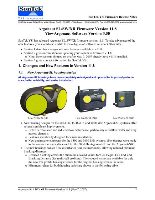
1.1. New <strong>Argonaut</strong>-SL housing design<br />
All <strong>Argonaut</strong>-SL housings have been completely redesigned and updated for improved performance,<br />
better reliability, and easier installation.<br />
• New housing designs for the 500-kHz, 1500-kHz, and 3000-kHz <strong>Argonaut</strong>-SL systems offer<br />
several significant improvements.<br />
o Better performance and reduced flow disturbance, particularly in shallow water and very<br />
narrow channels.<br />
o Features specifically designed for easier installation.<br />
o New underwater connector for the 1500 and 3000-kHz systems. (No changes were made<br />
to the connectors and cables used for the 500-kHz <strong>Argonaut</strong>-SL and the <strong>Argonaut</strong>-SW.)<br />
• The new housings reduce flow disturbance near the instrument, allowing reduced minimum<br />
blanking distances.<br />
o Reduced blanking affects the minimum allowed values for Cell Begin, Cell End, and<br />
Blanking Distance (for multi-cell profiling). The reduced values are available for only<br />
the new low profile housings; values for the original housing remain the same.<br />
o Minimum values for both housing styles are shown in the following table.<br />
1
<strong>SonTek</strong>/<strong>YSI</strong><br />
2<br />
New Low-Profile Housing Original Housing<br />
Frequency Min Cell Begin /<br />
Blanking Distance<br />
Min Cell End<br />
Min Cell Begin /<br />
Blanking Distance<br />
Min Cell End<br />
500 kHz 1.5 m (4.9 ft) 5.5 m (18.0 ft) 1.5 m (4.9 ft) 5.5 m (18.0 ft)<br />
1500 kHz 0.2 m (0.7 ft) 1.2 m (3.9 ft) 0.5 m (1.6 ft) 1.5 m (4.9 ft)<br />
3000 kHz 0.1 m (0.3 ft) 0.6 m (2.0 ft) 0.2 m (0.7 ft) 0.7 m (2.3 ft)<br />
For more information on the <strong>Argonaut</strong>-SL improvements, see:<br />
• <strong>Technical</strong> Note: <strong>Argonaut</strong>-SL New Features and Enhancements (April 2007):<br />
http://www.sontek.com/product/asl/sl-new0407.pdf<br />
• <strong>Argonaut</strong>-SL Brochure/Specifications:<br />
http://www.sontek.com/download/brochure/arg-sl.pdf<br />
1.2. Improved vertical beam performance<br />
Vertical beam performance has been improved, particularly for the new housings in very<br />
shallow water.<br />
• All vertical beam algorithms have been updated to provide improved reliability.<br />
• The minimum depth for vertical beam operation for all systems using the new housings has<br />
been improved, allowing operation in shallower water.<br />
o IMPORTANT: Monitor the aspect ratio closely in shallow water to avoid possible measurement<br />
contamination from surface or bottom effects. Refer to the <strong>Argonaut</strong>-SL manual<br />
or contact <strong>SonTek</strong>/<strong>YSI</strong> for more information.<br />
Cell End<br />
H S<br />
H B<br />
If H
2. Installing the Firmware Update<br />
<strong>Argonaut</strong> SL / SW / <strong>XR</strong> Firmware Version 11.8 (May 7, 2007)<br />
<strong>SonTek</strong>/<strong>YSI</strong><br />
Note: All production systems shipped on or after May 7, 2007 have version 11.8 already installed<br />
and do not require you to update the firmware.<br />
To install <strong>Argonaut</strong> firmware version 11.8:<br />
• Contact <strong>SonTek</strong> to obtain the firmware hex file (arg118.hex) and the access code file<br />
(arg118ac.txt) for your system. Be sure to provide your name, organization, and system<br />
serial number.<br />
• If applicable, download the latest version (4.00 or later) of SonUtils from the <strong>SonTek</strong> website<br />
(www.sontek.com). Look for the Support – Downloads page.<br />
• Install SonUtils on your computer following the instructions provided.<br />
• Connect the <strong>Argonaut</strong> to an available COM port of your computer.<br />
• Run SonUtils. Select the correct COM port in the upper left portion of the SonUtils window.<br />
• Click the Break icon to establish communications with the system. You should see a wake<br />
up message from the <strong>Argonaut</strong> in the SonUtils main window.<br />
• Click Instrument | Update Firmware.<br />
• Use the browse window to select the firmware hex file (arg118.hex).<br />
• Enter the access code when prompted (arg118ac.txt). Use a transfer mode of Binary and<br />
be sure the Verify new firmware and Use fast connection boxes are selected. Click Start<br />
when ready.<br />
• The software will show an updating display as the new firmware is loaded.<br />
• We hope you find the latest enhancements to the <strong>Argonaut</strong> firmware useful in your applications.<br />
To take advantage of these new features, we encourage you to update to the latest version<br />
of the View<strong>Argonaut</strong> program (version 3.50 or later), available through our web site at:<br />
www.sontek.com/product/sw/viewarg/viewargonaut.htm.<br />
3. Contact Information<br />
We welcome any comments, questions, or suggestions you have regarding <strong>Argonaut</strong> firmware<br />
version 11.8.<br />
<strong>SonTek</strong>/<strong>YSI</strong> Inc<br />
9940 Summers Ridge Road<br />
San Diego CA 92121-3091<br />
Tel: +1 (858) 546-8327<br />
Fax: +1 (858) 546-8150<br />
E-mail: support@sontek.com<br />
Web: www.sontek.com<br />
3
<strong>Argonaut</strong> SL / SW / <strong>XR</strong> Firmware Version 11.7 (December 7, 2006)<br />
<strong>SonTek</strong>/<strong>YSI</strong> Firmware Release Notes<br />
6837 Nancy Ridge Dr., Suite A • San Diego, CA 92121 • Telephone (858) 546-8327 • Fax (858) 546-8150 • Internet: www.sontek.com<br />
<strong>Argonaut</strong> SL/SW/<strong>XR</strong> Firmware Versions 11.6 and 11.7<br />
View<strong>Argonaut</strong> Software Version 3.43<br />
<strong>SonTek</strong>/<strong>YSI</strong> has released <strong>Argonaut</strong> SL/SW/<strong>XR</strong> firmware versions 11.6 and 11.7. To take advantage<br />
of the new features, you should also update to View<strong>Argonaut</strong> software version 3.43 or later.<br />
If you have any questions about these new features, please contact <strong>SonTek</strong>/<strong>YSI</strong>.<br />
NOTE: This document mainly describes firmware version 11.6. Version 11.7 was released December<br />
7, 2006 to correct a minor diagnostic issue discovered shortly after the release of v11.6<br />
• Section 1 describes changes and new features available in versions 11.6 and 11.7.<br />
• Section 2 gives information for updating your system to firmware version 11.7.<br />
o Note: All production systems shipped on or after December 7, 2006 have version 11.7<br />
already installed and do not require you to update the firmware.<br />
• Section 3 gives contact information for <strong>SonTek</strong>/<strong>YSI</strong>.<br />
1. Changes and New Features in Version 11.6 and 11.7<br />
1.1. Total volume criteria<br />
Total volume calculations allow the <strong>Argonaut</strong> to determine the amount of water that has passed<br />
the system over a given span of time; new criteria allow the modification of this calculation.<br />
• Total volume is the cumulative sum of flow rate multiplied by time. This represents the<br />
amount of water that has passed the system in a given amount of time.<br />
• By default, total volume includes all flow past the system regardless of the magnitude or direction<br />
of the flow.<br />
• New criteria modify the calculations to accumulate flow into total volume.<br />
o Total volume is only accumulated if the flow rate meets certain criteria:<br />
Flow ≥ a user-specified threshold<br />
Flow ≤ a user-specified threshold<br />
Magnitude (absolute value) of flow ≥ a user-specified threshold<br />
o Total volume is only accumulated if the velocity meets certain criteria:<br />
Velocity ≥ a user-specified threshold<br />
Velocity ≤ a user-specified threshold<br />
Magnitude (absolute value) of velocity ≥ a user-specified threshold<br />
• These conditions are provided to calculate a modified total volume value (e.g., only accumulate<br />
flow in a certain direction) or to avoid the accumulation of small, residual flow values<br />
in stagnant water.<br />
1.2. Change water level output to stage<br />
All real-time data from the vertical beam (SL and SW systems) are now output as “stage”<br />
rather than “water level”.<br />
• Water level is the height above the water surface above the top of the system.<br />
• Stage is water level plus the user-specified instrument elevation. This value thus reports water<br />
depth relative to a user-specified datum.<br />
• All real-time data outputs (RS232, SDI-12, analog output, and Modbus) now output stage<br />
rather than water level.<br />
1
<strong>SonTek</strong>/<strong>YSI</strong><br />
1.3. Assorted Changes<br />
The following list describes several minor changes and corrections.<br />
• The <strong>Argonaut</strong> Flow Display can now be used during SDI-12 data collection.<br />
• The maximum dimension of a trapezoid channel for flow calculations has been increased<br />
from 100 to 1000 m (328 to 3280 ft).<br />
• The maximum reference for analog output signals proportional to flow rate has been increased<br />
(to allow the analog output signal to be used for flow on larger rivers). The maximum<br />
reference value is now ±1,000,000 m 3 /s or ±10,000,000 ft 3 /s.<br />
• Ice detection algorithms have been improved to provide a more reliable indicator of ice coverage<br />
(<strong>Argonaut</strong>-SW).<br />
• An error in flow calculations for multiple (divided) channels has been corrected. Previously<br />
only the flow in the first (or multiple) channels was calculated. The system now calculates<br />
flow in all channels.<br />
• Flow calculations for the <strong>Argonaut</strong>-SW have been updated to correctly calculate flow when<br />
the SW is installed below the bottom of the channel (e.g., when the SW has been installed in<br />
a hole dug into the channel bottom).<br />
• The 750-kHz <strong>Argonaut</strong>-<strong>XR</strong> now operates reliably with very small cell size settings. Previously,<br />
small cell size values settings could potentially affect velocity data.<br />
2. Installing the Firmware Update<br />
Note: All production systems shipped on or after December 7, 2006 have version 11.7 already<br />
installed and do not require you to update the firmware.<br />
To install <strong>Argonaut</strong> firmware version 11.7:<br />
2<br />
• Contact <strong>SonTek</strong> to obtain the firmware hex file (Arg117.hex) and the access code for your<br />
system. Be sure to provide your name, organization, and system serial number.<br />
• If applicable, download the latest version (4.00 or later) of SonUtils from the <strong>SonTek</strong> website<br />
(www.sontek.com). Look for the Support – Downloads page.<br />
• Install SonUtils on your computer following the instructions provided.<br />
• Connect the <strong>Argonaut</strong> to an available COM port of your computer.<br />
• Run SonUtils. Select the correct COM port in the upper left portion of the SonUtils window.<br />
• Click the Break icon to establish communications with the system. You should see a wake<br />
up message from the <strong>Argonaut</strong> in the SonUtils main window.<br />
• Click Instrument | Update Firmware.<br />
• Use the browse window to select the firmware hex file (Arg117.hex).<br />
• Enter the access code when prompted. Use a transfer mode of Binary and be sure the Verify<br />
new firmware and Use fast connection boxes are selected. Click Start when ready.<br />
• The software will show an updating display as the new firmware is loaded.<br />
• We hope you find the latest enhancements to the <strong>Argonaut</strong> firmware useful in your applications.<br />
To take advantage of these new features, we encourage you to update to the latest version<br />
of the View<strong>Argonaut</strong> program (version 3.43 or later), available through our web site at:<br />
www.sontek.com/product/sw/viewarg/viewargonaut.htm.<br />
<strong>Argonaut</strong> SL / SW / <strong>XR</strong> Firmware Version 11.7 (December 7, 2006)
3. Contact Information<br />
<strong>Argonaut</strong> SL / SW / <strong>XR</strong> Firmware Version 11.7 (December 7, 2006)<br />
<strong>SonTek</strong>/<strong>YSI</strong><br />
We welcome any comments, questions, or suggestions you have regarding <strong>Argonaut</strong> firmware<br />
version 11.7.<br />
<strong>SonTek</strong>/<strong>YSI</strong>, Inc.<br />
6837 Nancy Ridge Dr, Ste A<br />
San Diego CA 92121-3217<br />
Tel: +1 (858) 546-8327<br />
Fax: +1 (858) 546-8150<br />
E-mail: support@sontek.com<br />
Web: www.sontek.com<br />
3
A <strong>YSI</strong> Environmental Company<br />
<strong>SonTek</strong>/<strong>YSI</strong> <strong>Argonaut</strong><br />
Acoustic Doppler Current Meter<br />
<strong>Technical</strong> Documentation
<strong>SonTek</strong>/<strong>YSI</strong><br />
6837 Nancy Ridge Drive, Suite A, San Diego, CA 92121 USA<br />
Telephone (858) 546-8327 • Fax (858) 546-8150<br />
E-mail: inquiry@sontek.com • Internet: www.sontek.com<br />
A <strong>YSI</strong> Environmental Company<br />
Getting Started with the <strong>Argonaut</strong> MD, SL, or <strong>XR</strong><br />
Thank you for your purchase. We are confident you will find the <strong>Argonaut</strong> powerful, accurate,<br />
reliable, and easy to use. If you have questions, comments, or suggestions, please let us know.<br />
1) Suggested Reading<br />
• We encourage you to read the <strong>Argonaut</strong> Principles of Operation. It provides valuable<br />
background information regarding theory, instrument use, and data analysis.<br />
• Refer to the <strong>Argonaut</strong> Operation <strong>Manual</strong> and the <strong>Argonaut</strong> Software <strong>Manual</strong> as needed<br />
for specific information about using the <strong>Argonaut</strong>.<br />
• See Section 2 of the <strong>Argonaut</strong> Operation <strong>Manual</strong> for more “Getting Started” instructions.<br />
2) Software Installation<br />
• Insert the <strong>Argonaut</strong> software CD into your computer’s CD-ROM drive. Wait a moment for<br />
the <strong>SonTek</strong> <strong>Argonaut</strong> Software menu to appear. Note: If the menu does not appear, use<br />
either Windows Explorer or Start | Run to locate and run Install.exe from the CD.<br />
• Use the Read Me option to learn more about the programs on the CD, and to review any<br />
last-minute information that may not be contained in the printed documentation.<br />
• Windows-based Software: Use the program setup options (e.g., View<strong>Argonaut</strong> Setup,<br />
SonUtils Setup) to install the individual Windows-based <strong>Argonaut</strong> programs. Follow the<br />
on-screen instructions. Note that you will be asked to enter Name, Company, and Serial<br />
information. For the Serial field, use the serial number of your instrument.<br />
• DOS-based Software: Create a directory on your hard disk in which to store the<br />
<strong>Argonaut</strong>’s DOS-based software. We recommend a directory name such as ArgDOS. Use<br />
the <strong>Argonaut</strong> DOS Programs option to manually copy the entire contents of this CD folder<br />
into the directory you created on your hard disk. Note that the subdirectory named SRC can<br />
also be copied to your computer. It contains source code for some of the DOS programs in<br />
case you wish to create your own data extraction and analysis programs.<br />
3) Quick Start: Real-Time Data Collection with Windows Software<br />
• Note: Steps 3 through 6 can also be done using DOS-based software. Refer to the<br />
<strong>Argonaut</strong> Software <strong>Manual</strong> for information on using the DOS-based software.<br />
• Plug the power and communication cable into the <strong>Argonaut</strong>, plug the serial connector into<br />
COM1 on your computer, and connect the power supply to the instrument.<br />
• Mount the instrument in a small tank with some seeding material in the water. (Testing<br />
can also be done in air, although the velocity data will be meaningless.)<br />
• Start View<strong>Argonaut</strong> using Start | Programs | <strong>SonTek</strong> Software | View<strong>Argonaut</strong>.<br />
Getting Started with the <strong>Argonaut</strong> MD, SL, or <strong>XR</strong> (May 1, 2001) 1
<strong>SonTek</strong><br />
2<br />
• Click Realtime to start the real-time data collection software.<br />
• Select a short averaging interval (10 seconds)<br />
• Press OK to configure the <strong>Argonaut</strong>.<br />
• Press the green play icon (!) to start data collection.<br />
• Press the red record icon (") to start recording to a file.<br />
• Collect a few minutes worth of data, generating real currents if possible.<br />
4) Quick Start: Post Processing with Windows Software<br />
• Start View<strong>Argonaut</strong> using Start | Programs | <strong>SonTek</strong> Software | View<strong>Argonaut</strong>.<br />
• Click PostProcessing to start the post processing software.<br />
• Select File | Open.<br />
• Select the file you recorded with the real-time software and click OK.<br />
• Click OK when file statistics are shown to finish loading the data.<br />
• Use the Zoom tool.<br />
• Double click the axis to change the plot scale.<br />
• Use the slide bar on the top to view tabular data for individual samples.<br />
• Export data in ASCII format using File | Export.<br />
5) Quick Start: System Diagnostics with Windows Software<br />
• Mount the <strong>Argonaut</strong> in a small tank of water with a little seeding material, ideally with the<br />
instrument close to a boundary (20-30 cm / 8-12 in).<br />
• Start View<strong>Argonaut</strong> using Start | Programs | <strong>SonTek</strong> Software | View<strong>Argonaut</strong>.<br />
• Click ArgCheck to start the system diagnostic software.<br />
• Refer to the <strong>Argonaut</strong> Software <strong>Manual</strong> for interpreting the software output.<br />
6) Direct Command Interface with Windows Software<br />
• The direct command interface allows you to “talk” directly to the <strong>Argonaut</strong>.<br />
• Start SonUtils using Start | Programs | <strong>SonTek</strong> Software | SonUtils.<br />
• Select SonTermW to start the terminal emulator software.<br />
• Click the BREAK icon (or press Alt+B) to wake-up the instrument. You should see a wakeup<br />
response from the instrument.<br />
• Use the Show icons to view all parameter settings.<br />
• Type help and press for assistance with the direct command interface.<br />
• Refer to the <strong>Argonaut</strong> Operation <strong>Manual</strong> for more details.<br />
Special Notice when Turning Computers On or Off<br />
When many computers and data loggers are turned on or off, they send a signal out the serial port<br />
that can be interpreted as a BREAK. If the <strong>Argonaut</strong> is connected to the serial port, this can<br />
interrupt data collection or awaken the <strong>Argonaut</strong> from its sleep mode. This may cause the loss of<br />
data or the draining of batteries. Always disconnect the <strong>Argonaut</strong> from the computer or data<br />
logger before turning the computer/data logger on or off.<br />
Getting Started with the <strong>Argonaut</strong> MD, SL, or <strong>XR</strong> (May 1, 2001)
<strong>SonTek</strong>/<strong>YSI</strong><br />
6837 Nancy Ridge Drive, Suite A, San Diego, CA 92121 USA<br />
Telephone (858) 546-8327 • Fax (858) 546-8150<br />
E-mail: inquiry@sontek.com • Internet: http://www.sontek.com<br />
A <strong>YSI</strong> Environmental Company<br />
<strong>Argonaut</strong><br />
Acoustic Doppler Current Meter<br />
Operation <strong>Manual</strong><br />
Firmware Version 7.9<br />
<strong>SonTek</strong>/<strong>YSI</strong><br />
Copyright 1995-2002 by <strong>SonTek</strong>/<strong>YSI</strong>, Inc. All rights reserved. This document may not, in whole or in part, be copied, photocopied, reproduced,<br />
translated, or reduced to any electronic medium or machine-readable form without prior consent in writing from <strong>SonTek</strong>. Every effort has been<br />
made to ensure the accuracy of this manual. However, <strong>SonTek</strong> makes no warranties with respect to this documentation and disclaims any<br />
implied warranties of merchantability and fitness for a particular purpose. <strong>SonTek</strong> shall not be liable for any errors or for incidental or<br />
consequential damages in connection with the furnishing, performance, or use of this manual or the examples herein. The information in this<br />
document is subject to change without notice.
WARRANTY, TERMS AND CONDITIONS<br />
<strong>Argonaut</strong> Operation <strong>Manual</strong> Firmware Version 7.9 (May 1, 2001)<br />
<strong>SonTek</strong>/<strong>YSI</strong><br />
Thank you for purchasing a <strong>SonTek</strong> Acoustic Doppler Velocity sensor. The instrument was<br />
thoroughly tested at the factory and found to be in excellent working condition. If the shipping<br />
crate appears damaged, or if the system is not operating properly, please contact <strong>SonTek</strong><br />
immediately.<br />
The System you have purchased is covered under a one year limited warranty that extends to all<br />
parts and labor for any malfunction due to workmanship or errors in the manufacturing process.<br />
The warranty does not cover shortcomings that are due to the design, nor does it cover any form<br />
of incidental damage because of errors in the measurements.<br />
In case your System is not functioning properly, first try to identify the source of the problem<br />
(refer to the appropriate section of the manual for a trouble shooting advice). If additional support<br />
is required, we encourage you to contact us immediately if a problem is detected and we will<br />
work to resolve the problem as quickly as possible. Most problems can be resolved without a<br />
system being returned to us.<br />
In case the system needs to be shipped back to the factory, please contact <strong>SonTek</strong> to obtain a<br />
Return Merchandise Authorization (RMA) number. We reserve the right to refuse receipt of<br />
shipments without RMAs. We require the system to be shipped back in original shipping<br />
container using original packing material and all delivery cost to <strong>SonTek</strong> covered by the<br />
customer (including all taxes and duties). If the system is returned without appropriate packing,<br />
the customer will be required to cover the cost of new packaging crate and material.<br />
i
<strong>SonTek</strong>/<strong>YSI</strong><br />
INTRODUCTION<br />
This manual is organized into the following sections:<br />
Section 1. <strong>Argonaut</strong> Components, Terminology, and Sampling – Naming conventions and<br />
terms used in this manual, plus a general description of <strong>Argonaut</strong> sampling strategies.<br />
Section 2. Getting Started – General instructions for collecting data with the <strong>Argonaut</strong> in the<br />
most common configurations.<br />
Section 3. Direct Command Interface – Direct communication with the <strong>Argonaut</strong>, including<br />
command format, options, and output data format.<br />
Section 4. Compass/Tilt Sensor Operation – Concerns and procedures relating to the internal<br />
compass and 2-axis tilt sensor.<br />
Section 5. <strong>Argonaut</strong> Hardware – Description of <strong>Argonaut</strong> electronics, cables, connectors, and<br />
instructions for accessing system components.<br />
Section 6. Operational Considerations – Concerns and procedures relating to power supply,<br />
instrument mounting, coordinate systems, maintenance, and troubleshooting.<br />
Section 7. Autonomous Deployment – Instructions for initiating an autonomous deployment<br />
(using internal recording and battery power). This section also includes detailed information on<br />
<strong>Argonaut</strong> power consumption, and a general discussion of operating parameter selection.<br />
Section 8. <strong>Argonaut</strong> Optional Features – Describes SonWave wave spectra collection package<br />
and external MicroCat CT sensor operation.<br />
Section 9. Additional Support – Contact information for additional customer support.<br />
Appendix 1. <strong>Argonaut</strong> Binary Data File Format<br />
Appendix 2. Internal SDI-12 Support for <strong>Argonaut</strong> SL/<strong>XR</strong><br />
Appendix 3. Vertical Beam Support for <strong>Argonaut</strong> SL Systems<br />
Appendix 4. Analog Output Option for <strong>Argonaut</strong> SL/<strong>XR</strong> Systems<br />
ii<br />
<strong>Argonaut</strong> Operation <strong>Manual</strong> Firmware Version 7.9 (May 1, 2001)
TABLE OF CONTENTS<br />
<strong>Argonaut</strong> Operation <strong>Manual</strong> Firmware Version 7.9 (May 1, 2001)<br />
<strong>SonTek</strong>/<strong>YSI</strong><br />
Section 1. <strong>Argonaut</strong> Components, Terminology, and Sampling ...................................... 1<br />
1.1. <strong>Argonaut</strong> Components .................................................................................................. 1<br />
1.2. Definitions and Terminology........................................................................................ 2<br />
1.3. <strong>Argonaut</strong> Sampling Strategies ...................................................................................... 3<br />
Section 2. Getting Started .................................................................................................... 5<br />
2.1. Real-Time Data Collection with <strong>SonTek</strong> Software ...................................................... 5<br />
2.2. Real-Time Data Collection using Serial Output Data .................................................. 5<br />
2.3. Autonomous Deployment............................................................................................. 6<br />
Section 3. Direct Command Interface................................................................................. 7<br />
3.1. Serial Communication Protocols and Settings ............................................................. 7<br />
3.2. Modes of Operation ...................................................................................................... 7<br />
3.2.1. Command Mode.............................................................................................. 8<br />
3.2.2. Data Acquisition Mode ................................................................................... 8<br />
3.2.3. Deployment Mode........................................................................................... 8<br />
3.2.4. Sleep Mode...................................................................................................... 9<br />
3.2.5. SDI-12 Mode................................................................................................... 9<br />
3.3. Special Notice when Changing Power Sources............................................................ 9<br />
3.4. Command Syntax........................................................................................................ 10<br />
3.5. Direct Command Summary ........................................................................................ 11<br />
3.6. Help Commands ......................................................................................................... 14<br />
3.7. System Commands ..................................................................................................... 15<br />
3.8. Setup Commands........................................................................................................ 18<br />
3.9. Deployment Commands ............................................................................................. 22<br />
3.10. SDI-12 Interface Commands ...................................................................................... 24<br />
3.11. Recorder Commands .................................................................................................. 25<br />
3.12. Sensor Commands ...................................................................................................... 27<br />
3.13. Compass Commands .................................................................................................. 28<br />
3.14. Show Commands........................................................................................................ 29<br />
3.15. Run-Time Commands................................................................................................. 31<br />
3.16. Output Data Format (Sample Data)............................................................................ 34<br />
3.16.1. Binary Data.................................................................................................... 34<br />
3.16.2. ASCII / METRIC / ENGLISH Sample Data................................................. 35<br />
3.17. Output Data Format (Profile Data) ............................................................................. 38<br />
Section 4. Compass/Tilt Sensor Operation....................................................................... 39<br />
4.1. Testing Compass Operation........................................................................................ 39<br />
4.2. Compass Installation................................................................................................... 40<br />
4.2.1. <strong>Argonaut</strong> MD ................................................................................................ 40<br />
4.2.2. <strong>Argonaut</strong> <strong>XR</strong> and SL..................................................................................... 42<br />
4.3. The ENU Coordinate System ..................................................................................... 44<br />
4.4. Compass Calibration................................................................................................... 44<br />
4.5. Communicating with the Compass............................................................................. 45<br />
iii
<strong>SonTek</strong>/<strong>YSI</strong><br />
Section 5. <strong>Argonaut</strong> Hardware.......................................................................................... 47<br />
iv<br />
5.1. <strong>Argonaut</strong> Hardware Configuration Settings ............................................................... 47<br />
5.2. <strong>Argonaut</strong> Internal Electronics and Wiring Overview ................................................. 48<br />
5.2.1. <strong>Argonaut</strong> MD ................................................................................................ 48<br />
5.2.2. <strong>Argonaut</strong> <strong>XR</strong> and SL..................................................................................... 49<br />
5.3. <strong>Argonaut</strong> Processor..................................................................................................... 51<br />
5.4. Communication Baud Rate Setting ............................................................................ 53<br />
5.5. Cables and Connectors ............................................................................................... 53<br />
5.5.1. Power/Communication Cable and Bulkhead Connector............................... 53<br />
5.5.2. Splitter Cable and Dummy Plug – <strong>Argonaut</strong> <strong>XR</strong> and SL with Batteries ...... 54<br />
5.6. Accessing Electronics................................................................................................. 55<br />
5.6.1. <strong>Argonaut</strong> MD ................................................................................................ 55<br />
5.6.2. <strong>Argonaut</strong> <strong>XR</strong> and SL..................................................................................... 56<br />
5.6.3. Replacing the CPU EPROM and Other Programmable Chips...................... 57<br />
5.7. Replacing Battery Packs ............................................................................................. 58<br />
5.7.1. <strong>Argonaut</strong> MD ................................................................................................ 58<br />
5.7.2. <strong>Argonaut</strong> <strong>XR</strong> and SL..................................................................................... 59<br />
Section 6. Operational Considerations ............................................................................. 61<br />
6.1. Input Power Supply..................................................................................................... 61<br />
6.2. Real-Time Clock Backup Battery............................................................................... 61<br />
6.3. <strong>Argonaut</strong> Mounting and Installation........................................................................... 62<br />
6.3.1. <strong>Argonaut</strong> MD ................................................................................................ 62<br />
6.3.2. <strong>Argonaut</strong> <strong>XR</strong> ................................................................................................. 63<br />
6.3.3. <strong>Argonaut</strong> SL .................................................................................................. 64<br />
6.3.4. External Battery Housing – <strong>Argonaut</strong> <strong>XR</strong> and SL ........................................ 65<br />
6.4. <strong>Argonaut</strong> Coordinate System...................................................................................... 66<br />
6.5. Serial Communication Protocol.................................................................................. 67<br />
6.6. Temperature and Pressure Sensors ............................................................................. 68<br />
6.7. Routine Maintenance .................................................................................................. 70<br />
6.8. Troubleshooting.......................................................................................................... 71<br />
6.9. Protection from Biological Fouling ............................................................................ 73<br />
Section 7. Autonomous Deployment ................................................................................. 75<br />
7.1. Selecting <strong>Argonaut</strong> Operating Parameters.................................................................. 75<br />
7.2. Calculating Battery Life and Data Storage Requirements .......................................... 76<br />
7.3. Starting an Autonomous Deployment......................................................................... 77<br />
Section 8. <strong>Argonaut</strong> Optional Features ............................................................................ 79<br />
8.1. Wave Spectra Collection Package: SONWAVE........................................................... 79<br />
8.1.1. Wave Frequency Spectra Calculations.......................................................... 79<br />
8.1.2. Setup for Collecting Wave Frequency Spectra ............................................. 80<br />
8.1.3. Wave Data Format ........................................................................................ 80<br />
8.2. Pressure Series Data Conversion: GARGPRES ........................................................ 81<br />
8.2.1. Considerations when collecting wave frequency spectra.............................. 81<br />
8.3. <strong>Argonaut</strong> External Sensors ......................................................................................... 82<br />
8.3.1. SeaBird MicroCat CTD................................................................................. 82<br />
<strong>Argonaut</strong> Operation <strong>Manual</strong> Firmware Version 7.9 (May 1, 2001)
<strong>Argonaut</strong> Operation <strong>Manual</strong> Firmware Version 7.9 (May 1, 2001)<br />
<strong>SonTek</strong>/<strong>YSI</strong><br />
8.3.2. CTD ASCII Data Format............................................................................... 83<br />
8.3.3. CTD Binary Data Format .............................................................................. 83<br />
Section 9. Additional Support............................................................................................ 85<br />
Appendix 1. <strong>Argonaut</strong> Binary Data File Format............................................................... 87<br />
Appendix 2. Internal SDI-12 Support for <strong>Argonaut</strong> SL/<strong>XR</strong> ............................................ 93<br />
Appendix 3. Vertical Beam Support for <strong>Argonaut</strong> SL Systems..................................... 111<br />
Appendix 4. Analog Output Option for <strong>Argonaut</strong> SL/<strong>XR</strong> Systems............................... 113<br />
v
<strong>SonTek</strong>/<strong>YSI</strong><br />
vi<br />
<strong>Argonaut</strong> Operation <strong>Manual</strong> Firmware Version 7.9 (May 1, 2001)
Section 1. <strong>Argonaut</strong> Components, Terminology, and Sampling<br />
<strong>SonTek</strong>/<strong>YSI</strong><br />
1.1. <strong>Argonaut</strong> Components<br />
The <strong>Argonaut</strong> includes several components depending on the exact instrument configuration. The<br />
list below gives a brief description of all major system components and their function.<br />
• <strong>Argonaut</strong> sensor - The sensor consists of two or three acoustic transducers (for 2D or 3D<br />
measurements) permanently mounted in the transducer head. The head is mounted to the<br />
pressure housing; the size and material used for construction vary with system configuration.<br />
• Receiver electronics - The receiver electronics consist of a circuit board mounted directly to<br />
the inside of the transducer head. The receiver provides the primary conditioning of the return<br />
signals from the acoustic transducers.<br />
• <strong>Argonaut</strong> processor - The <strong>Argonaut</strong> processor consists of two printed circuit boards inside the<br />
pressure housing. The processor is mounted on an internal mounting frame supported from<br />
the transducer head (§5.2). The processor sends and receives signals from the sensor,<br />
performs Doppler calculations to compute velocity, controls the operation of all other<br />
sensors, and outputs the data over the serial port and to the internal recorder.<br />
• Power and communication cable - This cable carries DC input power and serial communication<br />
between the processor and the controlling computer. The <strong>Argonaut</strong> can be configured for<br />
RS232 serial communication for cable lengths to 100 m (300 ft) or RS422 for cable lengths<br />
to 1500 m (4500 ft).<br />
• Splitter cable - This cable connects the <strong>Argonaut</strong> <strong>XR</strong> or SL to an external battery pack for<br />
autonomous operation. The cable has one connector to the <strong>Argonaut</strong>, a second to the battery<br />
pack, and a third to the power and communication cable (sealed with a dummy plug during<br />
deployment). See §5.5.2 for details.<br />
• Temperature sensor - The temperature sensor, standard on all <strong>Argonaut</strong> systems, is mounted<br />
on a titanium pin in the <strong>Argonaut</strong> transducer head. Temperature data are used to<br />
automatically compensate for changes in sound speed; sound speed is used to convert<br />
Doppler shift to water velocity. See §6.6 for details on the temperature sensor.<br />
• Compass/tilt sensor - This sensor measures magnetic heading and 2-axis tilt (maximum<br />
tilt ±50°). It comes standard with the <strong>Argonaut</strong> MD and <strong>XR</strong>, and is optional for the<br />
<strong>Argonaut</strong> SL. It allows the <strong>Argonaut</strong> to report velocity measurements in Earth coordinates<br />
(East / North / Up or ENU). The compass includes a built-in calibration feature to<br />
compensate for ambient magnetic fields. See Section 4 for more details.<br />
• Pressure sensor - The pressure sensor (standard on the <strong>XR</strong>; optional on the MD and SL) is<br />
mounted in the <strong>Argonaut</strong> transducer head between the acoustic transducers. In addition to its<br />
more general function of measuring deployment depth and surface elevation, data from the<br />
pressure sensor can be used by the <strong>Argonaut</strong> <strong>XR</strong> to automatically adapt operation for<br />
changing water level. See §6.6 for more details on the pressure sensor, see §3.8 for more<br />
details about the <strong>Argonaut</strong> <strong>XR</strong> dynamic boundary adjustment.<br />
• Battery power - The <strong>Argonaut</strong> can include battery power for autonomous deployment or to<br />
act as a backup in the event of shore power failure. For the <strong>Argonaut</strong> MD, the batteries are<br />
enclosed with the processor in a single pressure housing. For the <strong>Argonaut</strong> <strong>XR</strong> and SL, the<br />
batteries are housed in a separate underwater canister and are connected using a special<br />
splitter cable (§5.5.2). See Section 7 for details on autonomous operation from battery power.<br />
<strong>Argonaut</strong> Operation <strong>Manual</strong> Firmware Version 7.9 (May 1, 2001) 1
<strong>SonTek</strong>/<strong>YSI</strong><br />
1.2. Definitions and Terminology<br />
This section defines terms commonly used when working with the <strong>Argonaut</strong>.<br />
• Direct command interface - direct serial communication with the <strong>Argonaut</strong> to control system<br />
operation and retrieve data.<br />
• BREAK - a serial communication signal that causes a hardware reset in the electronics and<br />
returns the <strong>Argonaut</strong> to command mode.<br />
• Ping - a single estimate of the water velocity. A ping consists of each transducer sending an<br />
acoustic pulse, listening to the response, calculating the along beam velocity, and combining<br />
data from all beams to compute the 3D velocity.<br />
• Sample - refers to the collection of a number of pings to produce a mean estimate of water<br />
velocity. The mean sample includes velocity, standard deviation, and signal strength data, as<br />
well as data from other sensors.<br />
• Temperature - water temperature, in °C, is used for sound speed calculations. A default value<br />
is entered by the user, and another value is measured using an internal temperature sensor.<br />
• Salinity - water salinity, in ppt; a user-supplied value is used for sound speed calculations.<br />
• Sound speed - speed of sound in water, in m/s. This is used to convert the Doppler shift to<br />
velocity. Sound speed can be calculated either from user-specified temperature and salinity,<br />
or from measured temperature and user-input salinity (see TempMode in §3.8 for details). See<br />
<strong>Argonaut</strong> Principles of Operation regarding the effect of sound speed on velocity data.<br />
• Measurement volume / sampling volume – the volume of water in which the <strong>Argonaut</strong><br />
measures velocity. This volume is at a fixed location for the <strong>Argonaut</strong> MD, and is userprogrammable<br />
for the <strong>Argonaut</strong> <strong>XR</strong> and SL.<br />
• Cell begin – the location of the start of the measurement volume for the <strong>XR</strong> and SL. This is<br />
set by the user and is measured as distance along the axis of the instrument housing.<br />
• Cell end – the location of the end of the measurement volume for the <strong>XR</strong> and SL. This is set<br />
by the user and is measured as distance along the axis of the instrument housing.<br />
• Dynamic boundary adjustment – the automatic modification of the <strong>XR</strong> sampling volume<br />
based on data from the pressure sensor. This can be used to adapt operation to changing conditions<br />
in environments where surface elevation varies (e.g., tide or river stage variations).<br />
• Pinging rate - the number of pings per second, in Hz. The <strong>Argonaut</strong> is programmed to ping<br />
once per second.<br />
• Sample time - the <strong>Argonaut</strong> records date and time from its internal clock with each sample.<br />
The recorded time represents the start of the averaging interval.<br />
• Averaging interval - the period, in seconds, over which the <strong>Argonaut</strong> averages data before<br />
computing mean velocity.<br />
• Sample interval - the time between sequential samples, in seconds. This is defined as the time<br />
from the start of one sample to the start of the next sample, and must be greater than or equal<br />
to the averaging interval or the averaging interval will take precedence.<br />
• Burst sampling - this sampling method allows you to record a number of samples in rapid<br />
succession, and then place the <strong>Argonaut</strong> in a low-power state for an extended period. This<br />
obtains information about both the short- and long-term variation of water velocity without<br />
the power and memory required for continuous sampling.<br />
2<br />
<strong>Argonaut</strong> Operation <strong>Manual</strong> Firmware Version 7.9 (May 1, 2001)
<strong>Argonaut</strong> Operation <strong>Manual</strong> Firmware Version 7.9 (May 1, 2001)<br />
<strong>SonTek</strong>/<strong>YSI</strong><br />
• Burst interval - the time, in seconds, between each sampling burst (when burst sampling is<br />
enabled). This is measured from the start of one burst to the start of the next burst, and must<br />
be greater than the total time required for each burst.<br />
• Samples per burst - the number of samples recorded during each burst.<br />
1.3. <strong>Argonaut</strong> Sampling Strategies<br />
Many of the terms defined in §1.2 are used to determine the sampling strategy used by the<br />
<strong>Argonaut</strong>. These include ping, averaging interval, sample interval, burst interval, and samples per<br />
burst. These terms and the sampling strategies used by the <strong>Argonaut</strong> are shown in Figure 1. The<br />
<strong>Argonaut</strong> supports three basic sampling strategies.<br />
Continuous Sampling – Continuous sampling is used for real-time data collection when<br />
connected to shore power or for autonomous deployments without power or data limitations. For<br />
continuous operation, the <strong>Argonaut</strong> sample interval is set to the same value as the averaging<br />
interval, burst sampling is disabled, and the system continually collects data.<br />
Reduced Duty Cycle Sampling – For many autonomous deployments, the <strong>Argonaut</strong> uses a<br />
reduced duty cycle where the sample interval is greater than the averaging interval. When the<br />
<strong>Argonaut</strong> is not collecting data, it enters a low power state where power consumption is less than<br />
1 mW. Duty cycle is calculated as the ratio of the averaging interval to the sample interval.<br />
Battery life is extended by the inverse of the duty cycle. For example, an averaging interval of 5<br />
minutes with a sample interval of 15 minutes gives a 33% duty cycle and extends battery life by a<br />
factor of three.<br />
Burst Sampling – Burst sampling lets you obtain information about short-term flow variation<br />
without requiring continuous operation. In this mode, the <strong>Argonaut</strong> collects a number of samples<br />
in rapid succession and then enters a sleep mode to conserve power. Duty cycle during burst<br />
sampling is calculated by the following formula.<br />
Duty cycle = (Samples_per_burst * Averaging_interval) / Burst_interval<br />
See Section 7 for details about system power consumption, calculating battery life, and initiating<br />
autonomous deployments.<br />
3
<strong>SonTek</strong>/<strong>YSI</strong><br />
<strong>Argonaut</strong> Sample<br />
Continuous Sampling<br />
Reduced Duty Cycle Sampling<br />
4<br />
Ping<br />
Sample Interval<br />
Burst Sampling<br />
Sample Interval<br />
Averaging Interval<br />
Time<br />
Averaging Interval Burst Interval<br />
Averaging Interval = Sample Interval<br />
Averaging Interval<br />
Figure 1 – <strong>Argonaut</strong> Sampling Strategies<br />
Time<br />
Time<br />
Samples per Burst<br />
Time<br />
<strong>Argonaut</strong> Operation <strong>Manual</strong> Firmware Version 7.9 (May 1, 2001)
Section 2. Getting Started<br />
<strong>Argonaut</strong> Operation <strong>Manual</strong> Firmware Version 7.9 (May 1, 2001)<br />
<strong>SonTek</strong>/<strong>YSI</strong><br />
This section contains basic instructions for collecting data with the <strong>Argonaut</strong> in the three most<br />
common configurations. These instructions are not intended to be comprehensive, but should be<br />
sufficient to start collecting data for preliminary analysis.<br />
Note that the testing described here can be done with the system in air without any damage to the<br />
<strong>Argonaut</strong>, although the velocity data from the instrument will be meaningless. We suggest you<br />
begin with some basic testing with the system in the air and then move to field tests (from a dock<br />
or small boat) to gain experience.<br />
2.1. Real-Time Data Collection with <strong>SonTek</strong> Software<br />
The easiest way to collect <strong>Argonaut</strong> data is to use the real-time data collection software,<br />
ARGONAUT.EXE. This software is described in detail in the <strong>Argonaut</strong> Software <strong>Manual</strong>. Basic<br />
instructions for collecting data using ARGONAUT are given below.<br />
1. Copy all files from the software diskette to a directory on the controlling computer. Place the<br />
computer in a dedicated DOS mode (not a DOS prompt within Windows).<br />
2. Connect the <strong>Argonaut</strong> power and communication cable from the instrument to COM1 of the<br />
controlling computer and to the external power supply included with the system.<br />
3. Type ARGONAUT at the DOS prompt. The software will establish communication with the<br />
<strong>Argonaut</strong> and download the current system configuration.<br />
4. Select the desired operating parameters from the setup menu. For initial testing, we<br />
recommend using a relatively short averaging interval (perhaps 15 seconds) to speed up the<br />
data collection process. Specify a file in which to capture data on the computer hard disk.<br />
5. Select Start Data Acquisition from the setup menu. The software will configure the <strong>Argonaut</strong><br />
and begin data collection. Allow the <strong>Argonaut</strong> to collect several minutes of data.<br />
6. Stop data collection by pressing Alt+F10. After confirmation, the program will return to the<br />
setup menu. Select Exit Data Acquisition to return to the DOS prompt.<br />
7. Use the GARG*.EXE or EARG*.EXE programs to convert the binary data file to ASCII<br />
format. See the <strong>Argonaut</strong> Software <strong>Manual</strong> for details on program operation.<br />
2.2. Real-Time Data Collection using Serial Output Data<br />
The <strong>Argonaut</strong> is often integrated with a variety of data collection systems using the direct<br />
command interface and serial output data. For this type of integration, it may be helpful to gain<br />
experience with the system using the terminal emulator SonTerm included with the <strong>Argonaut</strong><br />
software. Basic instructions for getting started are given below. For more information on the<br />
direct command interface and output data format, see Section 3.<br />
1. Copy all files from the software diskette to a directory on the controlling computer. Place the<br />
computer in a dedicated DOS mode (not a DOS prompt within Windows).<br />
2. Connect the <strong>Argonaut</strong> power and communication cable from the instrument to COM1 of the<br />
controlling computer and to the external power supply included with the system.<br />
3. Type SONTERM at the DOS prompt.<br />
4. Capture all communication with the <strong>Argonaut</strong> to a file for future reference using the Alt+F<br />
option in SonTerm.<br />
5. Press Alt+B to send a BREAK to the <strong>Argonaut</strong> and bring the system into command mode (the<br />
<strong>Argonaut</strong> command prompt is “>”).<br />
5
<strong>SonTek</strong>/<strong>YSI</strong><br />
6. Begin using the direct command interface by typing Help at the command prompt. This will<br />
lead you into several menus displaying available commands.<br />
7. Use the four “Show” commands (“Show Conf”, “Show System”, “Show Setup”, and<br />
“Show Deploy”) to display all <strong>Argonaut</strong> hardware and operating parameter settings.<br />
8. Type “Compass CONT” to display data from the internal compass/tilt sensor (if present).<br />
Rotate and tilt the <strong>Argonaut</strong> to verify compass operation (§4.1). Press any key to stop data<br />
output.<br />
9. Type “Sensor CONT” to display data from the temperature, pressure, and battery voltage<br />
sensors (§3.12 and §6.6). Press any key to stop data output.<br />
10. Type “Dir” to view the contents of the internal recorder.<br />
11. Select reasonable operating parameters for trial data collection. Use relatively small values<br />
for averaging interval and sample interval (15 seconds). Select the output format as ASCII.<br />
12. Begin data collection immediately with the “Start” command.<br />
13. Allow the <strong>Argonaut</strong> to output a number of samples, then exit SonTerm (Alt+X) and take a<br />
closer look at the output data in the log file specified earlier.<br />
2.3. Autonomous Deployment<br />
Autonomous deployments use the <strong>Argonaut</strong> internal recorder and battery power. Section 7<br />
contains detailed instructions for initiating autonomous deployments. This section provides a<br />
brief overview of the steps used to collect a sample deployment from external power. It assumes<br />
you have already followed the steps in §2.2 and have a basic familiarity with the direct command<br />
interface.<br />
1. Copy all files from the software diskette to a directory on the controlling computer. Place the<br />
computer in a dedicated DOS mode (not a DOS prompt within Windows).<br />
2. Connect the <strong>Argonaut</strong> power and communication cable from the instrument to COM1 of the<br />
controlling computer and to the external power supply included with the system.<br />
3. Type SONTERM at the DOS prompt.<br />
4. Capture all communication with the <strong>Argonaut</strong> to a file for future reference using the Alt+F<br />
option in SonTerm.<br />
5. Press Alt+B to send a BREAK to the <strong>Argonaut</strong> and bring the system into command mode (the<br />
<strong>Argonaut</strong> command prompt is “>”).<br />
6. Use the four Show commands (Show Conf, Show System, Show Setup, and Show Deploy) to<br />
display all <strong>Argonaut</strong> hardware and operating parameter settings.<br />
7. Select relatively short values for averaging interval and sample interval (15 seconds) and<br />
disable burst sampling. Make sure the deployment start date and time are before the current<br />
date and time shown on the <strong>Argonaut</strong> internal clock. Specify a deployment name for the<br />
recorded data.<br />
8. Begin autonomous data collection with the “Deploy” command.<br />
9. Allow the <strong>Argonaut</strong> to output a number of samples, and then exit SonTerm (Alt+X).<br />
10. Type SONREC 1 at the DOS prompt to start the data retrieval software. When the directory is<br />
displayed, mark the file you have just generated using the spacebar and download by pressing<br />
the F3 key. When the data file has been downloaded, exit SonRec by pressing Esc.<br />
11. Use the GARG___.EXE or EARG___.EXE programs to convert the binary data file to ASCII<br />
format.<br />
6<br />
<strong>Argonaut</strong> Operation <strong>Manual</strong> Firmware Version 7.9 (May 1, 2001)
Section 3. Direct Command Interface<br />
<strong>Argonaut</strong> Operation <strong>Manual</strong> Firmware Version 7.9 (May 1, 2001)<br />
<strong>SonTek</strong>/<strong>YSI</strong><br />
Before data collection, you must understand the basic communication protocol and set some<br />
operational parameters. This can be done using the direct command interface or the software<br />
provided with the <strong>Argonaut</strong>. This section describes the direct command interface using a terminal<br />
or terminal emulator (such as SonTerm or SonTermW supplied with the <strong>Argonaut</strong> software).<br />
• Section 3.1 describes communication protocols and settings.<br />
• Section 3.2 provides an overview of the operational modes of the <strong>Argonaut</strong>.<br />
• Section 3.3 gives an important notice about cycling the <strong>Argonaut</strong> power source.<br />
• Section 3.4 presents the syntax rules for the direct-command interface.<br />
• Section 3.5 gives a summary of all available commands.<br />
• Sections 3.6 through 3.15 describe each command in detail.<br />
• Sections 3.16 and 3.17 describe data output formats.<br />
• Appendix 2 provides support for <strong>Argonaut</strong>-SLs that have the vertical beam option.<br />
3.1. Serial Communication Protocols and Settings<br />
The <strong>Argonaut</strong> can communicate using several serial communication protocols (see §6.5 for<br />
additional information).<br />
• RS232 – Single system operation with cable lengths to 100 meters (300 feet)<br />
• RS422 – Single system operation with cable lengths to 1500 meters (4500 feet)<br />
• SDI-12 – Single system operation with cable lengths to 100 meters (300 feet)<br />
The protocol is set at the factory based on user requirements. The different protocols have the<br />
following effects on the direct-command interface.<br />
• RS232 – Direct-command interface is described here in Section 3.<br />
• RS422 – Direct-command interface is described here in Section 3.<br />
• SDI-12 – This protocol uses a reduced direct-command interface, which is typically used<br />
in conjunction with RS232 for complete programming capabilities. See Appendix 2 for<br />
details on SDI-12 operation.<br />
The default communication settings for all communication protocols are below.<br />
• 9600 baud (§5.4 explains how to change baud rate settings)<br />
• 8 data bits (fixed)<br />
• No parity (fixed)<br />
• 2 stop bits (fixed)<br />
3.2. Modes of Operation<br />
The <strong>Argonaut</strong> has five operational modes, each of which is described in this section:<br />
• Command mode<br />
• Data acquisition mode<br />
• Deployment mode<br />
• Sleep mode<br />
• SDI-12 interface mode<br />
7
<strong>SonTek</strong>/<strong>YSI</strong><br />
3.2.1. Command Mode<br />
8<br />
• The <strong>Argonaut</strong> can send and receive commands related to all aspects of instrument<br />
operation.<br />
• You can enter the command mode from any other mode by sending a BREAK (§3.4).<br />
• You can enter the command mode from the data acquisition mode using the run-time<br />
command “+++” (§3.15).<br />
• You can put the <strong>Argonaut</strong> into any other mode only from the command mode.<br />
• To enter the data acquisition mode from the command mode, use the command Start.<br />
• To enter the deployment mode from the command mode, use the command Deploy.<br />
• To enter the SDI-12 interface mode from the command mode, use the command sdi12.<br />
• To enter the sleep mode from the command mode, use the command PowerOff.<br />
• If the <strong>Argonaut</strong> is left idle in the command mode for more than five minutes, it will enter<br />
the sleep mode to conserve power.<br />
3.2.2. Data Acquisition Mode<br />
• Data acquisition mode is used for real-time data collection for which you are typically<br />
connected to an external power supply and computer or data logger.<br />
• Data acquisition mode is entered from command mode with the command Start. After<br />
the Start command, the <strong>Argonaut</strong> takes a few seconds to initialize and then begins data<br />
collection.<br />
• In data acquisition mode, the <strong>Argonaut</strong> ignores the deployment parameters StartDate and<br />
StartTime.<br />
• If the internal recorder has been enabled (Recorder ON), data are output both over the<br />
serial port and to the internal recorder. If the recorder has been disabled (Recorder OFF),<br />
data are sent only to the serial port.<br />
• You can exit the data acquisition mode and return to the command mode by sending a<br />
BREAK (§3.4) or by using the run-time command “+++”.<br />
• While in data acquisition mode, the <strong>Argonaut</strong> can enter a low-power state between pings<br />
and between samples. This state is similar to, although not the same as, the sleep mode.<br />
The <strong>Argonaut</strong> will enter the low-power state if the system command AutoSleep is set to<br />
ON (the default setting). See §3.7 regarding the AutoSleep command and §3.15 regarding<br />
the effects of the power saving state on the run-time commands.<br />
3.2.3. Deployment Mode<br />
• Deployment mode is used for autonomous data collection (internal recording, typically<br />
with battery power).<br />
• Deployment mode is entered from command mode using the command Deploy.<br />
• In deployment mode, the instrument starts data collection at the date and time specified by<br />
StartDate and StartTime. If the current date and time are after the specified start date<br />
and time, the system begins data collection immediately.<br />
• In deployment mode, data are always stored to the internal recorder regardless of the<br />
Recorder ON/OFF parameter.<br />
• In deployment mode, the <strong>Argonaut</strong> will always enter the low-power state between pings<br />
and between samples regardless of the AutoSleep parameter (AutoSleep is forced ON).<br />
• Because of the power saving state, the run-time commands (§3.15) cannot be used.<br />
• You can exit the deployment mode and enter the command mode by sending a BREAK.<br />
<strong>Argonaut</strong> Operation <strong>Manual</strong> Firmware Version 7.9 (May 1, 2001)
3.2.4. Sleep Mode<br />
<strong>Argonaut</strong> Operation <strong>Manual</strong> Firmware Version 7.9 (May 1, 2001)<br />
<strong>SonTek</strong>/<strong>YSI</strong><br />
• Sleep mode is used to conserve power when the <strong>Argonaut</strong> is not in use. In the sleep mode,<br />
the <strong>Argonaut</strong> consumes less than 1 mW of power.<br />
• The sleep mode is entered from the command mode using the command PowerOff.<br />
• You can exit the sleep mode and enter command mode by sending a BREAK or by sending<br />
the command “+++” (§3.15).<br />
• When in sleep mode, the <strong>Argonaut</strong> will not respond to any other external commands. The<br />
exception is if system power is switched off and on (§3.3).<br />
• If the <strong>Argonaut</strong> is left idle in command mode for more than five minutes, it will<br />
automatically enter the sleep mode to conserve power.<br />
3.2.5. SDI-12 Mode<br />
• SDI-12 mode is used with SDI-12 communication protocol to match data-logger<br />
requirements. For more information, see Appendix 2.<br />
• SDI-12 mode is entered from command mode using the command sdi12 ON.<br />
• In SDI-12 mode, the <strong>Argonaut</strong> first performs all setup requirements for data collection. It<br />
then enters a low-power mode, awaiting commands from an external data logger.<br />
• In SDI-12 mode, the <strong>Argonaut</strong> collects one sample at a time on command from an external<br />
data-logger.<br />
3.3. Special Notice when Changing Power Sources<br />
When power to the <strong>Argonaut</strong> is turned off and on (e.g., when changing batteries or switching<br />
power supplies), the <strong>Argonaut</strong> enters the mode it was in before power was lost.<br />
• If previously in command or sleep mode, the system enters command mode.<br />
• If previously in data acquisition mode, the system immediately starts real-time data<br />
collection.<br />
• If previously in deployment mode, the system starts a new deployment. StartDate and<br />
StartTime are ignored and the new deployment begins immediately. This is a safety<br />
feature to avoid data loss in the unlikely event of a problem with the system clock.<br />
• If previously in SDI-12 mode, the system will again enter SDI-12 mode and wait for a<br />
command to begin a new sample.<br />
To Avoid Draining the Batteries When the System is Not in Use<br />
• Always power the system off before storing the system to prevent draining the batteries.<br />
• The splash-proof configuration can be powered off using the switch on the front panel.<br />
• All <strong>Argonaut</strong> configurations can be powered off by establishing direct communications<br />
using SonTerm and sending the command PowerOff (§3.7).<br />
IMPORTANT:<br />
• When some computers and data loggers are turned on or off, they send a signal out the<br />
serial port that can be interpreted by the <strong>Argonaut</strong> as a BREAK (§3.4).<br />
• If the <strong>Argonaut</strong> is connected to the serial port, this can interrupt data collection or bring the<br />
<strong>Argonaut</strong> out of sleep mode and cause the loss of data or the draining of the batteries.<br />
• Always disconnect the <strong>Argonaut</strong> from the computer or data logger before turning the<br />
computer on or off.<br />
9
<strong>SonTek</strong>/<strong>YSI</strong><br />
3.4. Command Syntax<br />
Throughout this manual, we refer to a BREAK when discussing direct communications with the<br />
<strong>Argonaut</strong>. Definition of BREAK:<br />
10<br />
• The BREAK is a serial communication signal that causes a hardware reset and places the<br />
instrument in command mode. A BREAK consists of holding the data input line high for a<br />
period of at least 300 milliseconds. Most terminal emulators include the ability to send a<br />
BREAK; SonTerm (supplied with the <strong>Argonaut</strong>) uses Alt+B.<br />
These are the basic rules for direct communication with the <strong>Argonaut</strong>.<br />
1. The <strong>Argonaut</strong> can be brought into the command mode from any other mode by sending a<br />
BREAK.<br />
2. All commands consist of a single keyword that may be followed by one or more ASCII<br />
parameters. The commands and parameters are not case sensitive.<br />
3. When the <strong>Argonaut</strong> has completed a command and is ready to accept another command, it<br />
will send the prompt character “>”.<br />
4. Parameters may be numeric (either integer or floating point), alphanumeric, or a<br />
combination (e.g., a date or time string).<br />
5. Commands must be terminated by a carriage return – .<br />
6. The <strong>Argonaut</strong> echoes every character as it is received (except for run-time commands<br />
received during data collection – see Section 3.15).<br />
7. After receiving the that signals the end of the command string, the <strong>Argonaut</strong> echoes<br />
with an additional line feed character – .<br />
8. If the <strong>Argonaut</strong> recognizes a command as valid it will transmit: OK.<br />
9. If a command is not recognized, the parameters are out of range, or the command cannot be<br />
executed in the present state, the <strong>Argonaut</strong> returns an error message followed by .<br />
IMPORTANT:<br />
• When some computers and data loggers are turned on or off, they send a signal out the<br />
serial port that can be interpreted by the <strong>Argonaut</strong> as a BREAK.<br />
• If the <strong>Argonaut</strong> is connected to the serial port, this can interrupt data collection or bring the<br />
<strong>Argonaut</strong> out of sleep mode and cause the loss of data or the draining of the batteries.<br />
• Always disconnect the <strong>Argonaut</strong> from the computer or data logger before turning the<br />
computer on or off.<br />
<strong>Argonaut</strong> Operation <strong>Manual</strong> Firmware Version 7.9 (May 1, 2001)
<strong>Argonaut</strong> Operation <strong>Manual</strong> Firmware Version 7.9 (May 1, 2001)<br />
<strong>SonTek</strong>/<strong>YSI</strong><br />
3.5. Direct Command Summary<br />
The tables below summarize all direct commands that can be used with the <strong>Argonaut</strong>, including<br />
any abbreviations (shorter versions of the same command). These commands are split into<br />
different sections, and different tables, based on their function. Further details on individual<br />
commands are provided in the sections that follow. The following abbreviations are used for<br />
input parameters to the <strong>Argonaut</strong>.<br />
• d Integer input (e.g., 30)<br />
• d.d Decimal real number input (e.g., 0.33, 1.5)<br />
• yy/mm/dd Date as year, month, and day (e.g., 1996/05/20 or 96/05/20)<br />
• hh:mm:ss 24-hour clock with hour, minute, and second (e.g., 18:15:00)<br />
Help Commands (Section 3.6)<br />
Command Short Function<br />
Help H or ? Available help categories<br />
Help System H/? System General system commands<br />
Help Setup H/? Setup Real-time data collection commands<br />
Help Deploy H/? Deploy Autonomous deployment commands<br />
Help Sdi12 H/? Sdi12 SDI-12 interface control commands (if applicable)<br />
Help Recorder H/? Recorder Data recorder commands<br />
Help Sensor H/? Sensor Peripheral sensor commands<br />
Help Compass H/? Compass Compass/tilt sensor commands<br />
Help Show H/? Show Commands to display system configuration<br />
System Commands (Section 3.7)<br />
Command Short Function Parameters<br />
Start (none)<br />
Starts real-time data collection (enters data<br />
acquisition mode)<br />
Deploy (none)<br />
Starts autonomous deployment (enters<br />
deployment mode)<br />
SaveSetup (none) Save current parameters to EEPROM<br />
Defaults DEF Sets all parameters to factory defaults<br />
Ver (none) Shows CPU firmware version<br />
DSPVer (none) Shows DSP firmware version<br />
BoardRev (none) Shows electronics board revision number<br />
SerNum (none) Shows <strong>Argonaut</strong> serial number<br />
Date (none) Shows / sets system clock date yy/mm/dd<br />
Time (none) Shows / sets system clock time hh:mm:ss<br />
PowerOff (none) Puts <strong>Argonaut</strong> in sleep mode<br />
AutoSleep AS<br />
If ON, <strong>Argonaut</strong> enters reduced power<br />
state during gaps in data collection<br />
On / Off<br />
OutMode OM Selects data output mode Auto / Polled<br />
OutFormat OF Specifies output data format<br />
Ascii, Binary,<br />
or SeaBird<br />
Recorder (none) Turns internal recording on or off On / Off<br />
RecMode (none) Sets recording mode (Buffer not enabled) Normal/Buffer<br />
11
<strong>SonTek</strong>/<strong>YSI</strong><br />
Setup Commands (Section 3.8)<br />
Command Short Function Parameters<br />
Temp (none) Set default temperature (°C) d.d<br />
Sal (none) Set default salinity (ppt) d.d<br />
AvgInterval AI Set averaging interval (seconds) d<br />
SampleInterval SI Set time between samples (seconds) d<br />
CellBegin CB<br />
Set start location of measurement volume<br />
(<strong>Argonaut</strong> <strong>XR</strong> and SL only)<br />
d.d<br />
CellEnd CE<br />
Set end location of measurement volume<br />
(<strong>Argonaut</strong> <strong>XR</strong> and SL only)<br />
d.d<br />
CoordSystem CY Set coordinate system for velocities<br />
BEAM, XYZ<br />
or ENU<br />
TempMode TM<br />
Set temperature used for sound speed<br />
calculations<br />
USER or<br />
MEASURED<br />
DataFormat DF Set output and stored data format<br />
LONG or<br />
SHORT<br />
ProfilingMode PM If installed, enable/disable profiling mode. YES or NO<br />
Ncells NC If PM=yes, number of cells to record d<br />
CellSize CS If PM=yes, length of range cell (m) d.d<br />
BlankDistance BD If PM=yes, distance to start of first cell (m) d.d<br />
DynBoundaryAdj<br />
<br />
DBA<br />
Set dynamic boundary adjustment mode<br />
(<strong>XR</strong> and SL with a pressure sensor only)<br />
YES or NO<br />
Deployment Commands (Section 3.9)<br />
Command Short Function Parameters<br />
Deployment (none) Set deployment name (5 characters max.) ASCII text<br />
Comments (none) Enter deployment comments ASCII text<br />
StartDate SD Set deployment start date yy/mm/dd<br />
StartTime ST Set deployment start time hh:mm:ss<br />
AvgInterval AI Set averaging interval (seconds) d<br />
SampleInterval SI Set time between samples (seconds) d<br />
BurstMode BM Enable or disable burst sampling YES or NO<br />
BurstInterval BI Set time between bursts (seconds) d<br />
SamplesPerBurst<br />
<br />
SB Set number of samples per burst d<br />
SDI-12 Interface Commands (Section 3.10)<br />
Command Short Function Parameters<br />
sdi12 (none) Places the system in the SDI-12 mode ON<br />
sdi12address (none) Sets the SDI-12 interface address d<br />
sdi12format (none) Sets the SDI-12 output data format<br />
?EXIT! (none) Exits the SDI-12 interface mode<br />
12<br />
SIDEKICK or<br />
SONTEK<br />
<strong>Argonaut</strong> Operation <strong>Manual</strong> Firmware Version 7.9 (May 1, 2001)
<strong>Argonaut</strong> Operation <strong>Manual</strong> Firmware Version 7.9 (May 1, 2001)<br />
<strong>SonTek</strong>/<strong>YSI</strong><br />
Recorder Commands (Section 3.11)<br />
Command Short Function Parameters<br />
LD or Dir (none) List deployments currently on recorder<br />
Format (none) Erase all data from recorder<br />
RecStatus (none) Show recorder size and free space left<br />
Recorder (none) Turns internal recording on or off ON or OFF<br />
RecMode (none)<br />
Sets recording mode (**BUFFER MODE<br />
IS NOT CURRENTLY ENABLED**)<br />
NORMAL or<br />
BUFFER<br />
OD (none) Open deployment to access data<br />
<br />
CD (none) Return name of currently open deployment<br />
RC (none)<br />
Retrieve configuration information from<br />
currently open deployment<br />
RSA [N] (none)<br />
Retrieve next N samples from file, ASCII<br />
format<br />
d<br />
RSB [N] (none)<br />
Retrieve next N sample from file, binary<br />
format<br />
d<br />
FS (none) Go to first sample in deployment<br />
LS (none) Go to last sample in deployment<br />
GS (none) Go to in deployment d<br />
CS (none) Return current sample number<br />
NS (none) Return number of samples in deployment<br />
Sensor Commands (Section 3.12)<br />
Command Short Function Parameters<br />
Sensor (none)<br />
Display most recent temperature, pressure,<br />
and battery voltage data<br />
Sensor CONT (none)<br />
Display continuous temperature, pressure,<br />
and battery voltage data<br />
PressOffset (none) Display pressure sensor calibration offset<br />
PressScale (none)<br />
Display pressure sensor calibration 1st<br />
order coefficient<br />
PressScale_2 (none)<br />
Display pressure sensor calibration 2nd<br />
order coefficient<br />
Compass Commands (Section 3.13)<br />
Command Short Function Parameters<br />
Compass (none)<br />
Display most recent heading, pitch, and<br />
roll data<br />
Compass CONT (none)<br />
Display continuous heading, pitch, and roll<br />
data<br />
Compass CAL (none) Perform a compass calibration<br />
13
<strong>SonTek</strong>/<strong>YSI</strong><br />
Show Commands (Section 3.14)<br />
Command Short Function<br />
Show Conf S Conf Display hardware configuration parameters<br />
Show System S System Display general system parameters<br />
Show Setup S Setup Display real time data collection parameters<br />
Show Deploy S Deploy Display autonomous deployment parameters<br />
Run-Time Commands (Section 3.15)<br />
Command* Short Function<br />
+++ (none) Return to command mode (stop data collection)<br />
O (none) Transmit last sample<br />
T (none) Transmit <strong>Argonaut</strong> date and time<br />
C+ (none) Adjust real-time clock +1 second<br />
C- (none) Adjust real-time clock -1 second<br />
A (none) Transmit time left in current averaging interval (seconds)<br />
*These commands available only in data acquisition mode.<br />
3.6. Help Commands<br />
The <strong>Argonaut</strong> direct command interface contains several on-line help commands. These are<br />
designed such that, by starting with “Help”, you are led through a series of menus that show all<br />
<strong>Argonaut</strong> commands. Several help commands display all commands you would normally use for<br />
any aspect of <strong>Argonaut</strong> operation.<br />
• Help Listing of help menus available<br />
• Help System General system commands<br />
• Help Setup Real-time data collection commands<br />
• Help Deploy Autonomous deployment commands<br />
• Help Sdi12 SDI-12 interface control commands<br />
• Help Recorder Data recorder commands<br />
• Help Sensor Peripheral sensor commands<br />
• Help Compass Compass/tilt sensor commands<br />
• Help Show Commands to display system configuration<br />
The output of these commands is self-explanatory. For more details on individual commands, see<br />
the remaining portions of Section 3.<br />
14<br />
<strong>Argonaut</strong> Operation <strong>Manual</strong> Firmware Version 7.9 (May 1, 2001)
3.7. System Commands<br />
System commands relate to general operation of the <strong>Argonaut</strong>.<br />
• Starting data collection<br />
• Displaying the serial number<br />
• Setting the clock<br />
• Data output and storage<br />
<strong>Argonaut</strong> Operation <strong>Manual</strong> Firmware Version 7.9 (May 1, 2001)<br />
<strong>SonTek</strong>/<strong>YSI</strong><br />
Each command is shown with its full name, short name (if one exists), optional parameters (in<br />
brackets), and appropriate detailed information.<br />
Start<br />
• Starts real-time data collection, putting the <strong>Argonaut</strong> into data acquisition mode (§3.2.2).<br />
• The system first saves all recently entered commands (i.e., does a SaveSetup).<br />
• Data collection begins immediately (StartDate and StartTime are ignored).<br />
• Burst sampling cannot be used (burst sampling parameters are ignored).<br />
• The system enters a low-power state between samples if AutoSleep is ON.<br />
• Run-time commands can only be used when AutoSleep is OFF.<br />
• Data will be stored to the recorder if enabled (Recorder ON).<br />
Deploy (do not confuse with Deployment command, §3.9)<br />
• Starts autonomous data collection, putting the <strong>Argonaut</strong> into deployment mode (§3.2.3).<br />
• The system first saves all recently entered commands (i.e., does a SaveSetup).<br />
• Data collection begins when the <strong>Argonaut</strong> clock reaches the specified StartDate and<br />
StartTime. If the current date/time is after the specified start date/time, data collection<br />
begins immediately.<br />
• <strong>Argonaut</strong> data are stored to the recorder regardless of the Recorder setting.<br />
• Instructs system to enter a low-power state between samples (AutoSleep is forced ON).<br />
SDI12 ON<br />
• The sdi12 ON command is used only with the SDI-12 serial interface.<br />
• See Appendix 2 for a description of the SDI-12 interface.<br />
SaveSetup<br />
• Saves all current parameter settings to internal memory (EEPROM).<br />
• This command must be sent before the system is shut down (or before a BREAK is sent);<br />
otherwise, any recently entered commands will be lost.<br />
• Executed automatically as part of the Start, Deploy, and sdi12 commands.<br />
Defaults or DEF<br />
• Sets all parameters (except baud rate) to the factory default values. The baud rate remains<br />
at the currently active value. To change the baud rate, see §5.4.<br />
• See the individual command descriptions for default values.<br />
Ver<br />
• Outputs the version number of the CPU firmware.<br />
15
<strong>SonTek</strong>/<strong>YSI</strong><br />
DSPVer<br />
• Outputs the version number of the DSP firmware.<br />
BoardRev<br />
• Outputs the revision number of the <strong>Argonaut</strong> processing electronics boards.<br />
SerNum<br />
• Returns the instrument serial number from memory (should match the serial number on<br />
the transducer head).<br />
Date [yy/mm/dd]<br />
• Without parameter: returns the date from the <strong>Argonaut</strong> clock.<br />
• When given a date in the form “yy/mm/dd” where yy = year (2 or 4 digits), mm = month<br />
(2 digits), and dd = day (2 digits), it resets the date.<br />
• Example: Date 2001/09/08 or Date 01/09/08 are equivalent commands setting the<br />
date to September 8, 2001.<br />
Time [hh:mm:ss]<br />
• Without parameter: returns the time from the <strong>Argonaut</strong> clock.<br />
• When given a time in the form of “hh:mm:ss” (24-hour clock, where hh = hour (2 digits),<br />
mm = minute (2 digits), and ss = seconds (2 digits)), it resets the time.<br />
• Example: Time 16:24:08 sets the time to 16:24:08 (4:24:08 p.m.).<br />
PowerOff<br />
• Places the <strong>Argonaut</strong> into sleep mode (§3.2.4).<br />
• We recommend placing the <strong>Argonaut</strong> in sleep mode whenever it is not in use.<br />
• The <strong>Argonaut</strong> will automatically enter sleep mode if it is left idle in command mode for<br />
more than five minutes.<br />
AutoSleep or AS [ON|OFF]<br />
• Default parameter: ON<br />
• Without parameter: returns its current setting.<br />
• Determines whether the <strong>Argonaut</strong> enters a reduced power state during data collection.<br />
• When ON, the <strong>Argonaut</strong> will enter the reduced power state between samples. Power<br />
consumption is less than 1 mW in the reduced power state.<br />
• When OFF, the <strong>Argonaut</strong> electronics remain active even when not collecting data.<br />
• Must be OFF to use the Run-Time commands (§3.15).<br />
• In deployment mode, AutoSleep is forced ON.<br />
OutMode or OM [AUTO|POLLED]<br />
• Default parameter: AUTO<br />
• Without parameter: returns its current setting.<br />
• Determines whether data are sent over the serial port after the completion of a sample<br />
(AUTO) or only sent when a specific run-time command is received (POLLED).<br />
• The run-time command “O” (Output) causes the output of the last sample from the buffer<br />
to be sent (§3.15).<br />
16<br />
<strong>Argonaut</strong> Operation <strong>Manual</strong> Firmware Version 7.9 (May 1, 2001)
OutFormat or OF [BINARY|ASCII|SEABIRD|METRIC|ENGLISH]<br />
• Default parameter: ASCII<br />
• Without parameter: returns its current setting.<br />
• Determines the format of the data output through the serial port. Section 3.16 has a<br />
description of the output data formats (BINARY, ASCII, SEABIRD, METRIC, ENGLISH).<br />
• Data stored on the internal recorder are always stored in binary format (§3.16).<br />
<strong>Argonaut</strong> Operation <strong>Manual</strong> Firmware Version 7.9 (May 1, 2001)<br />
<strong>SonTek</strong>/<strong>YSI</strong><br />
Recorder [ON|OFF]<br />
• Default parameter: ON<br />
• Without parameter: returns its current setting.<br />
• When ON, all data collected by the <strong>Argonaut</strong> will be stored on the internal recorder.<br />
• When OFF, any data collected in data acquisition mode (via the Start command) will not<br />
be stored to the recorder (but will be output to the serial port).<br />
• When in deployment mode (via the Deploy command), data are always stored on the<br />
internal recorder.<br />
RecMode [NORMAL|BUFFER]<br />
• This command is not enabled in this version of the firmware.<br />
17
<strong>SonTek</strong>/<strong>YSI</strong><br />
3.8. Setup Commands<br />
Setup commands affect the primary data collection parameters of the <strong>Argonaut</strong>.<br />
18<br />
• Temperature ● Cell begin<br />
• Salinity ● Cell end<br />
• Averaging interval ● Profiling mode<br />
• Sample interval ● Number of cells<br />
• Velocity Range ● Cell size<br />
• Coordinate system ● Blanking distance<br />
• Data format ● Dynamic boundary adjustment<br />
Note that the timing commands AvgInterval and SampleInterval are also listed under<br />
deployment commands (§3.9).<br />
Each command is shown with its full name, short name (if one exists), optional parameters (in<br />
brackets), parameter range (if appropriate), and detailed information.<br />
Temp [d.d]<br />
• Default parameter: 20.0 (°C)<br />
• Parameter range: -5.0 to 60.0 (°C)<br />
• Without parameter: returns its current setting.<br />
• When used with a valid input parameter, the user-specified temperature is set to this value.<br />
• This temperature value is used to calculate sound speed if TempMode is set to USER.<br />
• See the <strong>Argonaut</strong> Principles of Operation for the effect of sound speed on velocity data.<br />
Sal [d.d]<br />
• Default parameter: 34.5 (ppt)<br />
• Parameter range: 0.0 to 60.0 (ppt)<br />
• Without parameter: returns its current setting.<br />
• When used with a valid input parameter, the salinity is set to this value.<br />
• This salinity value is used to calculate sound speed.<br />
• See the <strong>Argonaut</strong> Principles of Operation for the effect of sound speed on velocity data.<br />
AvgInterval or AI [d]<br />
• Default parameter: 120 (s)<br />
• Parameter range: 10 to 3600 (s; maximum is equivalent to 60 minutes)<br />
• Without parameter: returns its current setting (in seconds).<br />
• When used with a valid integer parameter, the averaging interval is set to this value.<br />
SampleInterval or SI [d]<br />
• Default parameter: 1200 (s; 20 minutes)<br />
• Parameter range: 10 to 43200 (s; maximum is equivalent to 12 hours)<br />
• Without parameter: returns its current setting (in seconds).<br />
• When used with a valid integer parameter, the sample interval is set to this value.<br />
• Sample interval is the time between the start of successive samples (§1.2 and §1.3).<br />
• If AvgInterval > SampleInterval, then AvgInterval takes precedence.<br />
<strong>Argonaut</strong> Operation <strong>Manual</strong> Firmware Version 7.9 (May 1, 2001)
<strong>Argonaut</strong> Operation <strong>Manual</strong> Firmware Version 7.9 (May 1, 2001)<br />
<strong>SonTek</strong>/<strong>YSI</strong><br />
CoordSystem or CY [BEAM|XYZ|ENU]<br />
• Default parameter: ENU (for MD and <strong>XR</strong>); XYZ (for SL)<br />
• Without parameter: returns its current setting.<br />
• When used with a valid parameter, sets the coordinate system to this value.<br />
• BEAM causes velocity data to be stored and output as along-beam velocities.<br />
• XYZ causes velocity data to be recorded and output in the Cartesian coordinate system<br />
relative to the <strong>Argonaut</strong>.<br />
• ENU causes the <strong>Argonaut</strong> to use the compass/tilt sensor (if installed) data to transfer<br />
velocity data in Earth (East-North-Up) coordinates.<br />
• See §6.4 for coordinate system details.<br />
TempMode or TM [USER|MEASURED]<br />
• Default parameter: MEASURED<br />
• Without parameter: returns its current setting.<br />
• When used with a valid parameter, sets the temperature mode to this value.<br />
• Determines whether the user-input temperature (USER), or the value from the temperature<br />
sensor (MEASURED), is used for sound speed calculations.<br />
• The temperature sensor is specified as accurate to ±0.1°C. We recommend using<br />
MEASURED unless there is reason to suspect the temperature sensor has been damaged.<br />
• See <strong>Argonaut</strong> Principles of Operation for the effect of sound speed on velocity data.<br />
DataFormat or DF [LONG|SHORT]<br />
• Default parameter: LONG<br />
• Without parameter: returns its current setting.<br />
• When used with a valid parameter, sets the data format to this value.<br />
• Determines the format of data output over the serial port and to the internal recorder. LONG<br />
format includes all available diagnostic data and requires 33 bytes of data storage per<br />
sample (binary format). SHORT includes only minimal diagnostic data and requires 20 bytes<br />
of storage per sample (binary format). SHORT is intended only for autonomous<br />
deployments with large data storage requirements.<br />
• See §7.2 regarding the calculation of data storage requirements.<br />
CellBegin or CB [d.d] (used in <strong>XR</strong> and SL systems only)<br />
• Default parameter: 2.0 (meters)<br />
• Parameter range: 0.5 to 14.8 (for 1.5-MHz <strong>XR</strong> and SL systems)<br />
0.2 to 5.8 (for 3.0-MHz <strong>XR</strong> and SL systems)<br />
• Without parameter: returns its current setting (in meters).<br />
• When used with a valid parameter, sets the starting location of the measurement volume to<br />
this value in meters. The measurement volume location is specified as the vertical (<strong>XR</strong><br />
systems) or horizontal (SL systems) distance from the transducer head.<br />
• The measurement volume size (the difference between CellBegin and CellEnd) must be<br />
at least 0.5 meters.<br />
• See <strong>Argonaut</strong> Principles of Operation for the effect of sound speed on velocity data.<br />
19
<strong>SonTek</strong>/<strong>YSI</strong><br />
CellEnd or CE [d.d] (used in <strong>XR</strong> and SL systems only)<br />
• Default parameter: 2.0 (meters)<br />
• Parameter range: 0.7 to 15.0 (for 1.5-MHz <strong>XR</strong> and SL systems)<br />
0.4 to 6.0 (for 3.0-MHz <strong>XR</strong> and SL systems)<br />
• Without parameter: returns its current setting (in meters).<br />
• When used with a valid parameter, sets the ending location of the measurement volume to<br />
this value in meters. The measurement volume location is specified as the vertical (<strong>XR</strong><br />
systems) or horizontal (SL systems) distance from the transducer head.<br />
• The measurement volume size (the difference between CellBegin and CellEnd) must be<br />
at least 0.5 meters.<br />
• See <strong>Argonaut</strong> Principles of Operation for the effect of sound speed on velocity data.<br />
ProfilingMode or PM [YES|NO] (used in <strong>XR</strong> and SL systems only)<br />
• This command is only available in <strong>XR</strong> and SL systems that have the optional Profiling<br />
Mode feature installed. ProfilingMode allows you to collect a “profile” of data from a<br />
series of range cells. This differs from the standard <strong>Argonaut</strong> method of collecting data<br />
within just one range cell.<br />
• Default parameter: NO<br />
• Without parameter: returns its current setting.<br />
• When used with a valid parameter, enables (YES) or disables (NO) the profiling mode<br />
feature. Setting PM to YES requires you to enter values for the number of cells (Ncells;<br />
NC), cell size (CellSize; CS), and blanking distance (BlankDistance; BD). Data for each<br />
cell is collected and output in the format described in §3.17.<br />
Ncells or NC [d] (used in <strong>XR</strong> and SL systems only)<br />
• This command is only available in <strong>XR</strong> and SL systems that have the optional Profiling<br />
Mode feature installed (see above).<br />
• Default parameter: 1<br />
• Parameter range: 1 to 5<br />
• Without parameter: returns its current setting.<br />
• When used with a valid parameter, sets the number of cells in each profile.<br />
CellSize or CS [d.d] (used in <strong>XR</strong> and SL systems only)<br />
• This command is only available in <strong>XR</strong> and SL systems that have the optional Profiling<br />
Mode feature installed (see above).<br />
• Default parameter: 0.5 meter (for 1.5-MHz <strong>XR</strong> and SL systems)<br />
• Parameter range: 0.25 to 10 meters<br />
• Without parameter: returns its current setting in meters.<br />
• When used with a valid parameter, sets the range cell size in each profile to this value.<br />
BlankDistance or BD [d.d] (used in <strong>XR</strong> and SL systems only)<br />
• This command is only available in <strong>XR</strong> and SL systems that have the optional Profiling<br />
Mode feature installed (see above).<br />
• Default parameter: 0.5 meter (for 1.5-MHz <strong>XR</strong> and SL systems)<br />
20<br />
<strong>Argonaut</strong> Operation <strong>Manual</strong> Firmware Version 7.9 (May 1, 2001)
• Parameter range: 0.4 to 10 meters<br />
• Without parameter: returns its current setting in meters.<br />
• When used with a valid parameter, sets the blanking distance to this value.<br />
<strong>Argonaut</strong> Operation <strong>Manual</strong> Firmware Version 7.9 (May 1, 2001)<br />
<strong>SonTek</strong>/<strong>YSI</strong><br />
DynBoundaryAdj or DBA [YES|NO] (used in <strong>XR</strong> systems only)<br />
• This command is only available in <strong>XR</strong> systems.<br />
• Default parameter: NO<br />
• Without parameter: returns its current setting.<br />
• When set to YES, the <strong>XR</strong> dynamically adjusts the values of CellBegin and CellEnd to<br />
reflect the changes in a changing water level. Examples: (1) To monitor the currents in the<br />
upper 2 m of water below the surface, set CB to 13, CE to 15, and DBA to YES; (2) To measure<br />
currents throughout the entire water column, set CB to 0.4, CE to 15, and DBA to YES.<br />
• When set to NO, the <strong>XR</strong> uses the fixed cell location parameters (CellBegin and CellEnd)<br />
entered above. Example: When monitoring currents in a fixed layer (1 m above the<br />
bottom) set CB to 1, CE to 2, and DBA to NO.<br />
21
<strong>SonTek</strong>/<strong>YSI</strong><br />
3.9. Deployment Commands<br />
Deployment commands affect the parameters used for autonomous deployments.<br />
22<br />
• Deployment name<br />
• Averaging interval<br />
• Sample interval<br />
• Start date and time<br />
• Burst sampling parameters.<br />
Note that two of the timing commands (averaging interval and sample interval) are also listed<br />
under Setup Commands (§3.8).<br />
Each command is shown with its full name, short name (if one exists), optional parameters (in<br />
brackets), parameter range (if applicable), and appropriate detailed information.<br />
Deployment [name] (do not confuse with Deploy command, §3.7)<br />
• Default parameter: DEF<br />
• Without parameter: returns its current setting.<br />
• When used with an ASCII string of no more than five characters (letters or digits), the<br />
deployment name is set to this value. This determines the file name under which data are<br />
stored to the internal recorder.<br />
• All data from a single Deploy or Start command are stored in one file.<br />
• The file name on the recorder is the deployment name with a 3-digit number indicating the<br />
sequence of files under this name. For example, if the deployment name is LAKE, the data<br />
from the first Deploy or Start command will be stored in a file named LAKE001. If data<br />
collection is stopped and re-started without changing the deployment name, the numbers<br />
will increment; e.g. LAKE002, LAKE003, etc.<br />
Comments<br />
• This command lets you enter comments that will be stored in the data file.<br />
• There are three comment lines, each with a maximum of 60 characters.<br />
StartDate or SD [yy/mm/dd]<br />
• Default parameter: 1995/01/01 (January 1, 1995)<br />
• Without parameter: returns the deployment start date.<br />
• When used with a date in the correct format (see Date command, §3.7), sets the starting<br />
date for data collection. This date is used only in deployment mode (using the Deploy<br />
command, §3.7).<br />
• If the start date/time are before the current date/time, data collection begins immediately.<br />
StartTime or ST [hh:mm:ss]<br />
• Default parameter: 00:00:00<br />
• Without parameter: returns the deployment start time.<br />
• When used with a time in the correct format (see Time command, §3.7), sets the starting<br />
time for data collection. This time is used only in the deployment mode (using the Deploy<br />
command, §3.7).<br />
• If the start date/time are before the current date/time, data collection begins immediately.<br />
<strong>Argonaut</strong> Operation <strong>Manual</strong> Firmware Version 7.9 (May 1, 2001)
AvgInterval or AI [d]<br />
• See description under Setup Commands (§3.8).<br />
SampleInterval or SI [d]<br />
• See description under Setup Commands (§3.8).<br />
<strong>Argonaut</strong> Operation <strong>Manual</strong> Firmware Version 7.9 (May 1, 2001)<br />
<strong>SonTek</strong>/<strong>YSI</strong><br />
BurstMode or BM [NO|YES]<br />
• Default parameter: NO<br />
• Without parameter: returns its current setting.<br />
• Burst sampling can only be used in deployment mode (data collection started with the<br />
Deploy command). In data collection mode (using the Start command), this parameter is<br />
ignored. See §1.2 and §1.3 for a description of burst sampling.<br />
• NO disables burst sampling; YES enables burst sampling.<br />
BurstInterval or BI [d]<br />
• Default parameter: 1200 (s; maximum is equivalent to 20 minutes)<br />
• Parameter range: 1 to 43200 (s; maximum is equivalent to 12 hours)<br />
• Without parameter: returns its current setting.<br />
• When used with a valid integer parameter, the burst interval is set to this value (in<br />
seconds). See §1.2 and §1.3 for a description of burst sampling.<br />
• This command is ignored unless BurstMode is set to YES, and data collection is started<br />
with the Deploy command.<br />
SamplesPerBurst or SB [d]<br />
• Default parameter: 1<br />
• Parameter range: 1 to 1000<br />
• Without parameter: returns its current setting.<br />
• When used with a valid integer parameter, the number of samples per burst is set. See §1.2<br />
and §1.3 for a description of burst sampling.<br />
• This command is ignored unless BurstMode is set to YES, and data collection is started<br />
with the Deploy command.<br />
23
<strong>SonTek</strong>/<strong>YSI</strong><br />
3.10. SDI-12 Interface Commands<br />
Starting with firmware version 7.5, the <strong>Argonaut</strong>-<strong>XR</strong> and SL offers internal SDI-12 (Serial-<br />
Digital Interface) capabilities that require no external devices or converters. Appendix 2<br />
describes the internal SDI-12 interface support in detail. The <strong>Argonaut</strong> commands are described<br />
in this section, and the format of the SDI-12 commands is described in Appendix 2.<br />
sdi12 ON<br />
• Places an <strong>Argonaut</strong>-<strong>XR</strong> or SL system in the SDI-12 interface mode.<br />
• To exit the SDI-12 interface mode, you must use the ?EXIT! command described below.<br />
sdi12address [d]<br />
• Default parameter: 1<br />
• Parameter range: 0 through 9<br />
• Without parameter: returns either the current SDI-12 interface address (if the SDI-12<br />
interface option is installed), or an error message (if the SDI-12 option is not installed).<br />
• When used with a valid integer parameter, sets the <strong>Argonaut</strong>’s SDI-12 interface address.<br />
• If more than one sensor is to be connected to the SDI-12 bus, make certain each sensor has<br />
a unique address.<br />
sdi12format [SIDEKICK|SONTEK]<br />
• When given without parameter, returns the current data output format being used.<br />
• When given with a valid parameter, sets the data output format. Appendix 2 describes<br />
these two formats in detail.<br />
?EXIT!<br />
• Executing this command causes the <strong>Argonaut</strong> to exit the SDI-12 interface mode and return<br />
to the standard <strong>Argonaut</strong> operating mode.<br />
24<br />
<strong>Argonaut</strong> Operation <strong>Manual</strong> Firmware Version 7.9 (May 1, 2001)
3.11. Recorder Commands<br />
Recorder commands allow direct access to data stored in the <strong>Argonaut</strong> internal recorder.<br />
• Listing files<br />
• Checking recorder capacity<br />
• Extracting data<br />
<strong>Argonaut</strong> Operation <strong>Manual</strong> Firmware Version 7.9 (May 1, 2001)<br />
<strong>SonTek</strong>/<strong>YSI</strong><br />
Each command is shown with its full name, short name (if one exists), optional parameters (in<br />
brackets), and appropriate detailed information. The end of this section gives examples of how<br />
recorder commands can be used to access data on the internal recorder.<br />
Dir or LD<br />
• Lists a directory of the deployments currently stored on the recorder.<br />
Format<br />
• Erases all data from the recorder.<br />
• Naturally, you should take some care before executing this command.<br />
• Upon execution, you are asked to confirm the erasure of all data. The <strong>Argonaut</strong> will give<br />
an updated display showing its progress in re-formatting the memory card (the process will<br />
take a few seconds).<br />
RecStatus<br />
• Shows the installed recorder size and the amount of free space remaining.<br />
Recorder [ON|OFF]<br />
• See description under System Commands (§3.7).<br />
RecMode [NORMAL|BUFFER]<br />
• See description under System Commands (§3.7).<br />
OD [name] (for Open Deployment)<br />
• When the open deployment command is given an existing file name as its parameter, it<br />
allows access to data within that file.<br />
• Upon opening a file, a marker is placed on the first sample in the file. The file marker<br />
specifies the next sample to retrieve and is used by other recorder commands.<br />
CD (for Current Deployment)<br />
• Returns which recorder deployment file is now open.<br />
RC (for Retrieve Configuration)<br />
• Retrieves configuration information from the currently open file.<br />
• This includes all information in the file header that is stored only once per data file.<br />
• This information is retrieved in a self-explanatory ASCII text format.<br />
25
<strong>SonTek</strong>/<strong>YSI</strong><br />
RSA [N] (for Retrieve Sample in ASCII)<br />
• Retrieves N samples from the current file in ASCII format.<br />
• If N is not specified, one sample is retrieved.<br />
• The first sample retrieved will be the one given by the file marker; after executing this<br />
command, the file marker is moved to the next sample after those retrieved.<br />
• See Section 3.16 for a description of the output data format.<br />
RSB [N] (for Retrieve Sample in Binary)<br />
• Retrieves N samples from the current file in binary format.<br />
• If N is not specified, one sample is retrieved.<br />
• The first sample retrieved will be the one given by the file marker; after executing this<br />
command, the file marker is moved to the next sample after those retrieved.<br />
• See Section 3.16 for a description of the output data format.<br />
FS (for First Sample)<br />
• Moves the file marker to the first sample in the file.<br />
LS (for Last Sample)<br />
• Moves the file marker to the last sample in the file.<br />
GS [sample number] (for Go to Sample)<br />
• Moves the file marker to the sample number specified.<br />
• This sample will be the next retrieved with the RSA or RSB commands.<br />
CS (for Current Samples)<br />
• Returns the number of current samples shown by the file marker.<br />
NS (for Number of Samples)<br />
• Returns the number of samples in the currently open file.<br />
The following are examples of how to access recorder data from the direct-command interface.<br />
The <strong>Argonaut</strong> software includes a program to download data files (see the <strong>Argonaut</strong> Software<br />
<strong>Manual</strong>) and the direct access commands here are not needed for most applications.<br />
Example 1: Retrieve configuration data from deployment LAKE001.ARG<br />
26<br />
• LD to list deployments<br />
• OD LAKE001 to open the deployment<br />
• RC to retrieve configuration<br />
Example 2: Retrieve the last 5 samples in ASCII format from deployment LAKE001.ARG<br />
• LD to list deployments<br />
• OD LAKE001 to open the deployment<br />
• NS to retrieve the number of samples in the file (assume 1355 for this example)<br />
• GS 1351 to go to sample number 1351 in the file (fifth from the last sample)<br />
• RSA 5 to retrieve the last five samples in ASCII format<br />
<strong>Argonaut</strong> Operation <strong>Manual</strong> Firmware Version 7.9 (May 1, 2001)
<strong>Argonaut</strong> Operation <strong>Manual</strong> Firmware Version 7.9 (May 1, 2001)<br />
<strong>SonTek</strong>/<strong>YSI</strong><br />
3.12. Sensor Commands<br />
In normal <strong>Argonaut</strong> operation, all commands to the sensors are handled automatically, and no<br />
direct commands need to be sent. These commands are provided for diagnostic purposes only.<br />
See Section 6.6 for information about the temperature and pressure sensors.<br />
Each command is shown with its full name, short name (if one exists), optional parameters (in<br />
brackets), and appropriate detailed information.<br />
Sensor [CONT]<br />
• Without parameter: Display once the current temperature (°C), pressure (decibar), and<br />
battery voltage (V DC) data.<br />
• With parameter: Display continuously the temperature (°C), pressure (decibar), and<br />
battery voltage (V DC) data. Press any key to stop the output of sensor data.<br />
PressOffset<br />
• Display the pressure sensor offset value. See Section 6.6 for details on pressure sensor<br />
calibration.<br />
PressScale<br />
• Display the pressure sensor calibration 1 st order coefficient. See Section 6.6 for details on<br />
pressure sensor calibration.<br />
PressScale_2<br />
• Display the pressure sensor calibration 2 nd order coefficient value. See Section 6.6 for<br />
details on pressure sensor calibration.<br />
27
<strong>SonTek</strong>/<strong>YSI</strong><br />
3.13. Compass Commands<br />
In normal operation, all commands to the compass are sent automatically and no direct<br />
commands need to be sent. The commands in this section are provided to assist in diagnosing<br />
problems and to give greater flexibility in <strong>Argonaut</strong> operations. For a detailed description of the<br />
optional compass/tilt sensor, see Section 4.<br />
Each command is shown with its full name, short name (if one exists), optional parameters (in<br />
brackets), and appropriate detailed information.<br />
Compass [CONT]<br />
• Without parameter: Display once the most recent heading, pitch, and roll data from the<br />
compass/tilt sensor.<br />
• With parameter: Display continuously the heading, pitch, and roll data from compass/tilt<br />
sensor (updated twice per second). Press any key to stop data output and return to<br />
command mode.<br />
• Data are output in a self-explanatory, ASCII text format.<br />
Compass CAL<br />
• Perform a compass/tilt sensor calibration.<br />
• This is done to account for ambient magnetic fields that will affect compass heading<br />
(typically caused by ferrous metals) and should be performed before any deployment.<br />
• The <strong>Argonaut</strong> will output instructions for performing the calibration and provide a<br />
continuous display of heading, pitch, and roll.<br />
• Press any key to terminate the calibration, view the calibration score, and return to<br />
command mode.<br />
• See Section 4.4 for more information about compass calibration and for details on<br />
interpreting the calibration score.<br />
28<br />
<strong>Argonaut</strong> Operation <strong>Manual</strong> Firmware Version 7.9 (May 1, 2001)
<strong>Argonaut</strong> Operation <strong>Manual</strong> Firmware Version 7.9 (May 1, 2001)<br />
<strong>SonTek</strong>/<strong>YSI</strong><br />
3.14. Show Commands<br />
There are four “show” commands to display current <strong>Argonaut</strong>-ADV parameter settings. Samples<br />
of these commands and their outputs are shown below.<br />
Show Conf<br />
• Displays the <strong>Argonaut</strong> hardware configuration. See Section 5.1 for information about<br />
individual settings.<br />
• Example:<br />
>show conf<br />
HARDWARE CONFIGURATION PARAMETERS<br />
---------------------------------<br />
System Type -------------------- SL<br />
Sensor serial # ---------------- E15<br />
Sensor frequency - (kHz) ------- 1500<br />
Number of beams ---------------- 2<br />
Beam Geometry ------------------ 2_BEAMS<br />
Vertical Beam ------------------ NO<br />
Slant angle - (deg) ------------ 25.0<br />
Orientation -------------------- SIDE<br />
Compass installed ------------- NO<br />
Recorder installed ------------- YES<br />
Temperature sensor ------------- YES<br />
Pressure sensor ------------- NO<br />
PressOffset - (dbar) ---------- 0.000000<br />
PressScale -- (dbar/count) ---- 0.000000<br />
PressScale_2 - (pdbar/count^2) - 0<br />
Ctd sensor ------------- NO<br />
Ext. Press. sensor ------------- NONE<br />
<strong>YSI</strong> sensor ------------- NO<br />
Waves Option ------------------- NO<br />
Show System<br />
• Displays the current system parameters.<br />
• Example:<br />
>show system<br />
CURRENT SYSTEM PARAMETERS<br />
-------------------------<br />
CPU Ver --- ARG 3.0<br />
DSP Ver --- DSP 1.0<br />
BoardRev -- REV E<br />
Date ------ 2001/01/21<br />
Time ------ 09:26:35<br />
AutoSleep - YES<br />
OutMode --- AUTO<br />
OutFormat - ASCII<br />
Recorder -- ON<br />
RecMode --- NORMAL<br />
ModemMode - NO<br />
29
<strong>SonTek</strong>/<strong>YSI</strong><br />
Show Setup<br />
• Displays the current data collection setup parameters.<br />
• Example:<br />
30<br />
>show setup<br />
CURRENT SETUP PARAMETERS<br />
------------------------<br />
Temp ----------- 20.00 deg C<br />
Sal ------------ 34.50 ppt<br />
TempMode ------- MEASURED<br />
Sound Speed ---- 1520.9 m/s<br />
AvgInterval ---- 120 s<br />
SampleInterval - 1200 s<br />
CoordSystem ---- XYZ<br />
DataFormat ----- LONG<br />
CellBegin ------ 1.00 m<br />
CellEnd -------- 5.00 m<br />
ProfilingMode –- YES<br />
Ncells --------- 5<br />
CellSize ------- 4.00<br />
BlankDistance -- 0.50<br />
Show Deploy<br />
• Displays the current deployment parameters.<br />
• Example:<br />
>show deploy<br />
CURRENT DEPLOYMENT PARAMETERS<br />
-----------------------------<br />
Deployment ------ DEF<br />
StartDate ------- 1995/01/01<br />
StartTime ------- 00:00:00<br />
AvgInterval ----- 120 s<br />
SampleInterval -- 1200 s<br />
BurstMode ------- DISABLED<br />
BurstInterval --- 1200 s<br />
SamplesPerBurst - 1<br />
Comments:<br />
Get your <strong>Argonaut</strong> today<br />
Fun for the whole family<br />
Now with profiling mode option<br />
<strong>Argonaut</strong> Operation <strong>Manual</strong> Firmware Version 7.9 (May 1, 2001)
3.15. Run-Time Commands<br />
This section describes how to communicate with the <strong>Argonaut</strong> while the system is in data<br />
acquisition mode.<br />
<strong>Argonaut</strong> Operation <strong>Manual</strong> Firmware Version 7.9 (May 1, 2001)<br />
<strong>SonTek</strong>/<strong>YSI</strong><br />
• Run-time commands are commonly used while using the POLLED output mode (see<br />
OutMode in §3.7). This causes the system only to output a data sample on request, and not<br />
to output data automatically at the end of a sample.<br />
• To “talk” to an <strong>Argonaut</strong> during a deployment (i.e., when it is in the data acquisition<br />
mode), you must first re-establish communications with the system. This is done by<br />
sending a few carriage returns (; ASCII character code 13) over the communications<br />
cable using a terminal emulator such as <strong>SonTek</strong>’s SonTerm or SonTermW. Note: You may<br />
have to send more than one because during some phases of its operation, the<br />
<strong>Argonaut</strong> does not recognize the arrival of just one character.<br />
• After the <strong>Argonaut</strong> recognizes the , it responds with a $ prompt. This indicates that<br />
for the next 10 seconds run-time commands will be accepted. If no additional characters<br />
are received within 10 seconds, the <strong>Argonaut</strong> automatically resumes its regular power<br />
management mode of operation. If this occurs, the sequence will have to be repeated to<br />
talk to the system. Note: When several carriage returns are sent and recognized, the<br />
<strong>Argonaut</strong> ignores them and just resets the 10-s countdown. In addition, if the <strong>Argonaut</strong> is<br />
in the middle of an averaging interval, it continues transmitting (pinging) at the nominal<br />
1-Hz rate whether the system has been awakened or not. As long as you do not send a<br />
BREAK or the “+++” sequence, the system continues collecting data as usual.<br />
• After the <strong>Argonaut</strong> responds with the $ prompt, you can use any of the commands<br />
described below to communicate with the system. The commands can be used without<br />
causing any delay or interruption of data collection (except for a few milliseconds that the<br />
system spends in executing the command). <strong>Argonaut</strong> responses to any of these commands<br />
may be delayed up to one second (this is the frequency at which the incoming command<br />
buffer is checked), so allow up to a 1-s delay after sending a command.<br />
+++ (alternative BREAK command)<br />
• Sending three + characters in succession causes the <strong>Argonaut</strong> to terminate data collection<br />
and return to the command mode.<br />
• The characters must arrive within a time span of 3 seconds.<br />
• This command is provided as an alternative to sending a BREAK when relaying data over a<br />
modem (where sending a BREAK command may not be possible).<br />
• This command can also be used to wake the <strong>Argonaut</strong> from sleep mode. Note that the<br />
system may not recognize the first + character. You may need to send more than three +<br />
characters in succession to wake the system.<br />
O (output last sample)<br />
• Sending an “O” (letter O) tells the <strong>Argonaut</strong> to output the last data sample collected. Note:<br />
This command is not available if OutFormat = SEABIRD.<br />
• The last sample is stored internally and is updated at the end of each averaging interval.<br />
• At the end of each averaging interval, the <strong>Argonaut</strong> places the sample in an output buffer<br />
in the format specified by the OutFormat command (BINARY, ASCII, METRIC, ENGLISH;<br />
see §3.16).<br />
31
<strong>SonTek</strong>/<strong>YSI</strong><br />
32<br />
• If OutMode (output mode) = AUTO, the <strong>Argonaut</strong> immediately transmits the buffer contents<br />
through the serial port. If OutMode = POLLED, the <strong>Argonaut</strong> continues data collection<br />
without transmitting the buffer contents.<br />
• In either output mode (AUTO or POLLED), the last sample remains in the output buffer until<br />
the next sample is completed. At this time, the contents of the buffer are replaced with the<br />
new sample.<br />
• When using the POLLED output mode, it is your responsibility to request transmission of<br />
the buffer after each sample is collected and before the averaging interval for the next<br />
sample is completed.<br />
• The data sample upload can be done as many times as desired without significantly<br />
affecting data collection, since the <strong>Argonaut</strong> uses only a few milliseconds of processing<br />
time to retransmit the entire data buffer.<br />
T (output date/time)<br />
• Sending a “T” during data collection tells the <strong>Argonaut</strong> to output the current date and time<br />
from its internal clock. Note: This command is not available if OutFormat = SEABIRD.<br />
• The clock is read immediately before the date/time data are output, which can be up to one<br />
second after the T command is sent.<br />
• The date/time output will be in ASCII or BINARY format depending on the current setting<br />
of the OutFormat parameter. If OutFormat is set to ASCII, METRIC, or ENGLISH, time is<br />
output in ASCII format.<br />
• In ASCII format, the following line will be sent.<br />
yyyy/mm/dd hh:mm:ss.hh <br />
• In BINARY format, the following nine bytes will be sent.<br />
Run Time Command “T” Binary Output Record<br />
Field Offset Length Description<br />
Year 0 2 Integer four digit calendar year (e.g., 1995)<br />
Month 2 1 Unsigned character<br />
Day 3 1 Unsigned character<br />
Hour 4 1 Unsigned character<br />
Minute 5 1 Unsigned character<br />
Sec100 7 1 Unsigned character - hundredths of a second<br />
Second 6 1 Unsigned character<br />
CheckSum 8 1 1-byte checksum of preceding eight bytes<br />
(Appendix 1 explains checksum calculation.)<br />
C+ and C- (clock adjust)<br />
• The C command is used to adjust the <strong>Argonaut</strong>’s internal clock.<br />
• C+ advances the clock one second.<br />
• C- sets the clock back one second.<br />
• The <strong>Argonaut</strong> acknowledges successful completion of this command with:<br />
OK .<br />
<strong>Argonaut</strong> Operation <strong>Manual</strong> Firmware Version 7.9 (May 1, 2001)
<strong>Argonaut</strong> Operation <strong>Manual</strong> Firmware Version 7.9 (May 1, 2001)<br />
<strong>SonTek</strong>/<strong>YSI</strong><br />
A (averaging interval time left)<br />
• Sending an “A” during data collection tells the <strong>Argonaut</strong> to output the time remaining in<br />
the current averaging interval (in seconds). Note: This command is not available if<br />
OutFormat = SEABIRD.<br />
• The remaining time is output in either ASCII or BINARY format depending on the setting of<br />
the OutFormat parameter. If OutFormat is set to ASCII, METRIC, or ENGLISH, the time<br />
remaining is output in ASCII format.<br />
• In ASCII format, the following line will be sent, where is an integer value<br />
without leading spaces.<br />
<br />
• In BINARY format, the following five bytes will be sent:<br />
Run Time Command “A” Binary Output Record<br />
Field Offset Length Description<br />
Time left 0 4 Time left in seconds as a 4-byte integer<br />
CheckSum 4 1 2-byte checksum of preceding 4 bytes<br />
(Appendix 1 explains checksum calculation.)<br />
33
<strong>SonTek</strong>/<strong>YSI</strong><br />
3.16. Output Data Format (Sample Data)<br />
34<br />
• The <strong>Argonaut</strong> can output data over the serial port in a variety of formats depending on the<br />
setting of the OutFormat command (§3.7).<br />
o BINARY – Used for the most efficient data transmission and storage.<br />
o ASCII – Standard tab-delimited ASCII format with all variables output as integers (no<br />
decimal points in data).<br />
o SEABIRD – Specialized format for integrating with SeaBird inductive modem.<br />
o METRIC – Tab-delimited ASCII format with all variables in metric units.<br />
o ENGLISH – Tab-delimited ASCII format with all variables in English units.<br />
• The setting of OutFormat affects only data sent to the serial port.<br />
• Data written to the internal recorder are always stored in binary format.<br />
• ASCII and BINARY formats are used for data sent to the serial port during data collection<br />
and for data retrieved using the recorder commands.<br />
• SEABIRD, METRIC, and ENGLISH formats are used only for data output over the serial port<br />
during data collection.<br />
3.16.1. Binary Data<br />
Binary data files generated by the <strong>Argonaut</strong>, using either the real-time data collection software or<br />
the internal recorder, use the same format. Appendix 1 has a detailed description of the <strong>Argonaut</strong><br />
binary file format. <strong>Argonaut</strong> binary sample data uses the same format for several different<br />
methods of access.<br />
• Output over the serial port during data collection<br />
• Using the run-time command “O” (§3.15)<br />
• Using the recorder command RSB (§3.11)<br />
• Each <strong>Argonaut</strong> sample will consist of several different data records, depending on the<br />
setting of the DataFormat parameter (LONG or SHORT – see §3.8).<br />
• For most applications, the LONG record is used to enable access to all available diagnostic<br />
data. The LONG data format uses a 38-byte record for each sample. The last byte of this<br />
record is a checksum of the preceding 37 bytes. See Appendix 1 for details.<br />
• For autonomous deployments with data storage limitations, and for some other specialized<br />
applications, the SHORT record may be used to reduce the amount of data per sample (at the<br />
cost of eliminating some of the diagnostic data). The SHORT data format uses a 22-byte<br />
record for each sample. The last byte of this record is a checksum of the preceding 21<br />
bytes. See Appendix 1 for details.<br />
• See <strong>Argonaut</strong> Principles of Operation for information about interpreting the data types.<br />
<strong>Argonaut</strong> Operation <strong>Manual</strong> Firmware Version 7.9 (May 1, 2001)
<strong>Argonaut</strong> Operation <strong>Manual</strong> Firmware Version 7.9 (May 1, 2001)<br />
<strong>SonTek</strong>/<strong>YSI</strong><br />
3.16.2. ASCII / METRIC / ENGLISH Sample Data<br />
When outputting <strong>Argonaut</strong> data over the serial port in ASCII/METRIC/ENGLISH format, there<br />
are two basic data output types.<br />
• First are the hardware configuration and user-setup parameters.<br />
o These are output using the RC recorder command.<br />
o This output contains all parameters relating to the hardware configuration of the<br />
<strong>Argonaut</strong> (serial number, frequency, number of beams, etc.) and all user-setup<br />
parameters (averaging interval, sample interval, temperature, and salinity, etc.).<br />
o This output is presented in a self-explanatory text format.<br />
• The second ASCII data output type contains data from one <strong>Argonaut</strong> sample.<br />
o This is output over the serial port during data collection using the “O” run-time<br />
command (§3.15) and the RSA recorder command (§3.11).<br />
o The output is one line per sample in a tabular format that can be easily loaded by data<br />
processing software.<br />
o The exact format of the output sample depends on the setting of the data format<br />
parameter (LONG or SHORT).<br />
o See <strong>Argonaut</strong> Principles of Operation for information about interpreting data types.<br />
<strong>Argonaut</strong> LONG Sample Format<br />
• When LONG data format is specified, the data output consists of 28 columns. The following<br />
table shows the contents and units used with each column.<br />
• All <strong>Argonaut</strong>s sample temperature and pressure once per second. The mean value of<br />
temperature and mean and standard deviation of pressure are reported.<br />
• The nature of the data from the compass/tilt sensor (heading, pitch, and roll) depends on<br />
the system configuration.<br />
o For the <strong>Argonaut</strong> MD, the reported values represent the mean over the averaging<br />
period (as the system may move during the course of an averaging period). Compass<br />
and tilt sensor data are sampled with each ping (once per second).<br />
o For the <strong>Argonaut</strong> <strong>XR</strong> (and SL with compass/tilt sensor), compass and tilt sensor data<br />
are sampled once at the beginning of the averaging period. This value is used to rotate<br />
velocity data from the instrument’s XYZ coordinates to ENU coordinates and is<br />
reported with the data.<br />
o For the <strong>Argonaut</strong> <strong>XR</strong> and SL, the system is assumed stationary during the course of<br />
each averaging period.<br />
35
<strong>SonTek</strong>/<strong>YSI</strong><br />
36<br />
<strong>Argonaut</strong> ASCII/METRIC/ENGLISH Data Output - LONG Data Format<br />
Col Contents ASCII Metric English<br />
1 Sample time (start of averaging interval) - Year<br />
2 Sample time (start of averaging interval) - Month<br />
3 Sample time (start of averaging interval) - Day<br />
4 Sample time (start of averaging interval) - Hour<br />
5 Sample time (start of averaging interval) - Minute<br />
6 Sample time (start of averaging interval) - Second<br />
7 Velocity component 1 (Beam 1/X/East) 0.1 cm/s cm/s ft/s<br />
8 Velocity component 2 (Beam 2/Y/North) 0.1 cm/s cm/s ft/s<br />
9 Velocity component 3 (Beam 3/Z/Up) – OR –<br />
0.1 cm/s cm/s ft/s<br />
Water level (SL systems with vertical beam; Appendix 2) mm cm ft<br />
10 Standard deviation component 1 (Beam 1/X/East) 0.1 cm/s cm/s ft/s<br />
11 Standard deviation component 2 (Beam 2/Y/North) 0.1 cm/s cm/s ft/s<br />
12 Standard deviation component 3 (Beam 3/Z/Up) 0.1 cm/s cm/s ft/s<br />
13 Signal strength (Beam 1) counts counts counts<br />
14 Signal strength (Beam 2) counts counts counts<br />
15 Signal strength (Beam 3) count count count<br />
16 Percent good pings % % %<br />
17 Heading 0.1° ° °<br />
18 Pitch (rotation about the Y-axis) 0.1° ° °<br />
19 Roll (rotation about the X-axis) 0.1° ° °<br />
20 Standard deviation heading 0.4° ° °<br />
21 Standard deviation pitch 0.4° ° °<br />
22 Standard deviation roll 0.4° ° °<br />
23 Mean temperature 0.01°C °C °F<br />
24 Mean pressure count dBar PSI<br />
25 Standard deviation of pressure count dBar PSI<br />
26 Input power level 0.2 V V V<br />
27 Starting location of sampling volume (vertical distance) 0.1 m m ft<br />
28 Ending location of sampling volume (vertical distance) 0.1 m m ft<br />
29+ Note: Additional fields may appear depending on installed<br />
options. See Section 8 for the data format of wave spectra,<br />
CTD, and other optional sensors.<br />
<strong>Argonaut</strong> Operation <strong>Manual</strong> Firmware Version 7.9 (May 1, 2001)
<strong>Argonaut</strong> Operation <strong>Manual</strong> Firmware Version 7.9 (May 1, 2001)<br />
<strong>SonTek</strong>/<strong>YSI</strong><br />
<strong>Argonaut</strong> SHORT Sample Format<br />
• When SHORT data format is used, the data output contains 14 columns. The following table<br />
shows the contents and units used with each column.<br />
• For the SHORT data format, reported signal strength is the mean of all working beams<br />
(three beams for <strong>Argonaut</strong> <strong>XR</strong> and MD; two beams for <strong>Argonaut</strong> SL).<br />
• Reported standard deviation is the defined based on the coordinate system:<br />
Beam Coordinates σV = √(σV1 2 + σV2 2 + σV3 2 )<br />
XYZ Coordinates σV = √(σVx 2 + σVy 2 )<br />
ENU Coordinate σV = √(σVE 2 + σVN 2 )<br />
<strong>Argonaut</strong> ASCII/METRIC/ENGLISH Data Output - SHORT Data Format<br />
Col Contents ASCII Metric English<br />
1 Sample time (start of averaging interval) - Year<br />
2 Sample time (start of averaging interval) - Month<br />
3 Sample time (start of averaging interval) - Day<br />
4 Sample time (start of averaging interval) - Hour<br />
5 Sample time (start of averaging interval) - Minute<br />
6 Sample time (start of averaging interval) - Second<br />
7 Velocity component 1 (Beam 1/X/East) 0.1 cm/s cm/s ft/s<br />
8 Velocity component 2 (Beam 2/Y/North) 0.1 cm/s cm/s ft/s<br />
9 Velocity component 3 (Beam 3/Z/Up) 0.1 cm/s cm/s ft/s<br />
10 Mean standard deviation (see above) 0.1 cm/s cm/s ft/s<br />
11 Mean signal strength (see above) count count count<br />
12 Mean temperature 0.01°C °C °F<br />
13<br />
Mean pressure – OR –<br />
Water level (SL systems with vertical beam; Appendix 2)<br />
count<br />
mm<br />
dbar<br />
cm<br />
PSI<br />
ft<br />
14 Input power level 0.2 V V V<br />
15+ Note: Additional fields may appear depending on installed<br />
options. See Section 8 for the data format of wave spectra,<br />
CTD, and other optional sensors.<br />
37
<strong>SonTek</strong>/<strong>YSI</strong><br />
3.17. Output Data Format (Profile Data)<br />
Systems manufactured with the optional Profiling Mode feature will output profile data for each<br />
cell. The format of the data is shown in this section. Before profile data can be displayed, you<br />
must set the ProfilingMode (PM) command to YES. You must also make entries for number of<br />
cells (NC), cell size (CS), and blanking distance (BD). See §3.8 for command descriptions.<br />
The following example and table show the format of <strong>Argonaut</strong> profile data.<br />
38<br />
1 -251 -39 23 0 0 0 31 59 72<br />
2 129 155 -20 0 0 0 31 59 71<br />
3 0 2186 56 0 0 0 0 0 0<br />
4 -267 88 134 0 0 0 31 59 72<br />
<strong>Argonaut</strong> Profile Data Format<br />
Column Contents<br />
1 Cell number<br />
2 Velocity data (V1 or Vx or Veast) in cm/s<br />
3 Velocity data (V2 or Vy or Vnorth) in cm/s<br />
4 Velocity data (V3 or Vz or Vup) in cm/s [3-beam systems only]<br />
5 Standard deviation data (SD1 or SDx or SDeast in cm/s<br />
6 Standard deviation data (SD2 or SDy or SDnorth in cm/s<br />
7 Standard deviation data (SD3 or SDz or SDup in cm/s [3-beam systems only]<br />
8 Amplitude (signal strength), Beam 1 in counts (1 count = 0.43 dB)<br />
9 Amplitude (signal strength), Beam 2 in counts<br />
10 Amplitude (signal strength), Beam 3 in counts [3-beam systems only]<br />
<strong>Argonaut</strong> Operation <strong>Manual</strong> Firmware Version 7.9 (May 1, 2001)
Section 4. Compass/Tilt Sensor Operation<br />
<strong>Argonaut</strong> Operation <strong>Manual</strong> Firmware Version 7.9 (May 1, 2001)<br />
<strong>SonTek</strong>/<strong>YSI</strong><br />
• The <strong>Argonaut</strong> MD and <strong>XR</strong> are equipped with a compass and 2-axis tilt sensor, which<br />
provides heading, pitch, and roll data. The <strong>Argonaut</strong> SL is not normally equipped with the<br />
compass/tilt sensor, but can be for specialized applications.<br />
• The sensor used is the Precision Navigation TCM2.<br />
• Compass data is used to translate velocity from the instrument XYZ coordinate system to<br />
an Earth coordinate system (East-North-Up or ENU; see §4.3).<br />
While the compass provides excellent quality data, there are some limitations to keep in mind.<br />
• Ensure the compass is correctly mounted for the orientation of the <strong>Argonaut</strong> (up- or downlooking),<br />
and that the installation matches the system orientation setting. See §4.2 for<br />
details about compass installation and orientation setting.<br />
• The compass includes a built-in calibration feature to account for the effects of ambient<br />
magnetic fields (e.g., nearby ferrous metals). We recommend performing a compass<br />
calibration before each deployment. When properly calibrated, the compass provides<br />
heading accurate to ±2.0° and pitch and roll accurate to ±1.0° up to 50°. See §4.4 for<br />
details about compass calibration.<br />
• Because the compass communicates with the <strong>Argonaut</strong> through an RS-232 interface, it is<br />
possible for you to communicate directly with the compass. All communication with the<br />
compass is handled automatically by the <strong>Argonaut</strong>, and direct communication with the<br />
compass should not normally be necessary. For a discussion of how to communicate<br />
directly with the compass/tilt sensor, see §4.5.<br />
4.1. Testing Compass Operation<br />
A simple procedure exists to verify compass operation using a continuous display of heading,<br />
pitch, and roll. This is not intended as a precise test of compass accuracy, but a means to evaluate<br />
basic performance. For best results, we recommend performing a compass calibration before any<br />
deployment (§4.4).<br />
• The compass must be physically oriented up (which means the <strong>Argonaut</strong> will be oriented<br />
down if the compass is installed for down-looking operation) and the orientation setting<br />
must match the compass installation. See §4.2 for compass installation/orientation details.<br />
• This test should be conducted in an area predominantly free of magnetic material.<br />
• Start the display of compass data:<br />
o If using the direct-command interface, the command Compass CONT gives a<br />
continuous output of heading, pitch, and roll (§3.13).<br />
o Or, use <strong>SonTek</strong>’s compass calibration software, CompCal or CompCalW (see<br />
<strong>Argonaut</strong> Software <strong>Manual</strong>) to view a graphical display of compass data.<br />
• Point the <strong>Argonaut</strong> X-axis (marked on the transducer head) towards each compass<br />
direction (North, South, East, and <strong>West</strong>) and compare the compass output with the<br />
expected reading.<br />
• Test the pitch and roll sensors by tilting the <strong>Argonaut</strong> about the X-axis (roll) and Y-axis<br />
(pitch) respectively, and compare the output measurements with estimated tilt angles.<br />
• The data should appear reasonable within the accuracy of this type of experiment (±10°<br />
heading, ±5° tilt). Large errors or a lack of response indicates a problem with the compass.<br />
39
<strong>SonTek</strong>/<strong>YSI</strong><br />
4.2. Compass Installation<br />
The <strong>Argonaut</strong> is configured at the factory for up or down-looking operation. You can determine<br />
the configuration by using the Show Conf command from the direct command interface (§3.14<br />
and §5.1). Both the installation of the compass and the orientation setting must be modified if the<br />
<strong>Argonaut</strong> is switched between up and down-looking operation.<br />
The critical part of compass installation is to maintain a known orientation relative to the<br />
acoustic transducers. This allows the <strong>Argonaut</strong> to use the compass data to translate velocity data<br />
from the XYZ coordinate system (relative to the <strong>Argonaut</strong>) to the ENU coordinate system.<br />
Figure 2 shows the compass/tilt sensor layout<br />
and its XYZ coordinate system. The<br />
compass must be operated with the component<br />
side facing upwards (within the ±50°<br />
tilt limit); operation in any other orientation<br />
will result in invalid compass data and corrupted<br />
velocity data when using the ENU coordinate<br />
system (non-recoverable data loss).<br />
The compass has a 10-pin connector at one<br />
end for communication with the <strong>Argonaut</strong>.<br />
The positive X-axis is defined along the long<br />
axis of the compass board from the connector<br />
towards the magnetic coils. The positive<br />
Z-axis is defined perpendicular to the compass board, upwards from the side with the connector,<br />
coils, and tilt sensor. The positive Y-axis is defined for a right hand coordinate system.<br />
Pitch is defined as a rotation about the Y-axis; positive pitch raises the magnetic coils above the<br />
connector. Roll is defined as a rotation about the X-axis; positive roll raises the magnetic coils<br />
above the tilt sensor.<br />
4.2.1. <strong>Argonaut</strong> MD<br />
The standard <strong>Argonaut</strong> MD system includes a compass/tilt sensor; it is installed at the factory to<br />
meet the orientation requirements of the user. If changing between up and down-looking<br />
operation, you must modify the compass installation and change the orientation setting as<br />
described below. See §5.6.1 for instructions on accessing the <strong>Argonaut</strong> MD electronics.<br />
Up-looking compass installation<br />
Figure 3 shows the installation of the <strong>Argonaut</strong> MD compass/tilt sensor for up-looking operation.<br />
The system is drawn with the transducer head looking down (as if placed on a table), but the<br />
compass is installed for up looking operation. Both the compass X-axis and the <strong>Argonaut</strong> X-axis<br />
are coming out of the page (the transducer shown is Beam 1). The compass is installed so that the<br />
component side will be facing up when the <strong>Argonaut</strong> transducers are up-looking.<br />
For up-looking operation, the compass is mounted directly to a set of four 3/8” standoffs on the<br />
internal mounting plate (these standoffs are secured with lock-tite and cannot be easily removed).<br />
The positive X-axis of the compass is aligned with the positive X-axis of the <strong>Argonaut</strong> (the<br />
compass coordinate system exactly matches the <strong>Argonaut</strong> up-looking XYZ coordinate system).<br />
See §6.4 for the definition of the <strong>Argonaut</strong> XYZ coordinate system; note that this coordinate<br />
40<br />
Y<br />
X<br />
Top View<br />
Z<br />
10 pin<br />
Connector<br />
Magnetic<br />
Coils<br />
Tilt<br />
Sensor<br />
X<br />
Side View<br />
Figure 2 – Compass/Tilt Coordinate System<br />
<strong>Argonaut</strong> Operation <strong>Manual</strong> Firmware Version 7.9 (May 1, 2001)
system will change depending on whether<br />
the orientation setting is for up or downlooking<br />
operation.<br />
When installing the compass, the board is<br />
secured using short #4-40 screws (spares are<br />
included in the <strong>Argonaut</strong> tool kit). Install<br />
fiber washers on both sides of the compass<br />
board for protection. It may be helpful to<br />
stick the washers to the compass board with<br />
a small amount of silicon grease before<br />
installing the compass (the o-ring grease in<br />
the <strong>Argonaut</strong> tool kit works well). The<br />
compass mounting screws should be<br />
tightened securely, but not over-tightened.<br />
After installing the compass, you need to<br />
specify the system orientation so that the<br />
<strong>Argonaut</strong> will correctly interpret the<br />
compass data. To specify the orientation for<br />
up-looking operation, establish direct<br />
communication with the <strong>Argonaut</strong> and send<br />
the following command.<br />
ORIENTATION SET UP<br />
<strong>Argonaut</strong> Operation <strong>Manual</strong> Firmware Version 7.9 (May 1, 2001)<br />
<strong>SonTek</strong>/<strong>YSI</strong><br />
After sending the command, send a BREAK to the system. List the hardware configuration<br />
parameters by sending a Show Conf command and verify that orientation is correctly set. The<br />
system is now ready for operation.<br />
Z<br />
Down-looking compass installation<br />
Figure 4 shows the installation of the <strong>Argonaut</strong><br />
MD compass/tilt sensor for down-looking operation.<br />
The system is drawn with the transducer<br />
head looking down as if placed on a table. Both<br />
the compass X-axis and the <strong>Argonaut</strong> X-axis are<br />
coming out of the page (the transducer shown is<br />
beam 1). The compass is installed so that the<br />
component side will be facing up when the<br />
<strong>Argonaut</strong> transducers are down-looking.<br />
For down-looking operation, four 1” standoffs<br />
are attached to the four 3/8” standoffs installed<br />
on the internal mounting plate (the 3/8” standoffs<br />
are secured with lock-tite and cannot be easily<br />
removed). The positive X-axis of the compass is<br />
aligned with the positive X-axis of the <strong>Argonaut</strong><br />
(the compass coordinate system exactly matches<br />
the <strong>Argonaut</strong> down-looking XYZ coordinate<br />
system). See §6.4 for the definition of the<br />
Y<br />
Z<br />
Compass and<br />
<strong>Argonaut</strong><br />
Coordinate<br />
System<br />
2.5"<br />
3/8"<br />
Tilt Sensor<br />
Magnetic Coils<br />
Figure 3 – <strong>Argonaut</strong> MD<br />
Up-Looking Compass Installation<br />
3/8"<br />
Y<br />
1"<br />
Compass and<br />
<strong>Argonaut</strong><br />
Coordinate<br />
2.5"<br />
System Tilt Sensor Magnetic Coils<br />
Figure 4 – <strong>Argonaut</strong> MD<br />
Down-Looking Compass Installation<br />
41
<strong>SonTek</strong>/<strong>YSI</strong><br />
<strong>Argonaut</strong> XYZ coordinate system; note that this coordinate system will change depending on<br />
whether the orientation setting is for up or down-looking operation.<br />
When installing the compass, the board is secured using short #4-40 screws (spares are included<br />
in the <strong>Argonaut</strong> tool kit). Install fiber washers on both sides of the compass board for protection.<br />
It may be helpful to stick the washers to the compass board with a small amount of silicon grease<br />
before installing the compass (the o-ring grease in the <strong>Argonaut</strong> tool kit works well). The<br />
compass mounting screws should be tightened securely, but not over-tightened.<br />
After installing the compass, you need to specify the system orientation so the <strong>Argonaut</strong> will<br />
correctly interpret the compass data. To specify the orientation for down-looking operation,<br />
establish direct communication with the <strong>Argonaut</strong> and send the following command.<br />
42<br />
ORIENTATION SET DOWN<br />
After sending the command, send a BREAK to the system. List the hardware configuration<br />
parameters by sending a Show Conf command and verify that orientation is correctly set. The<br />
system is now ready for operation.<br />
4.2.2. <strong>Argonaut</strong> <strong>XR</strong> and SL<br />
The standard <strong>Argonaut</strong> <strong>XR</strong> system includes a compass/tilt sensor; unless otherwise specified, the<br />
compass is installed for up-looking operation. For most applications of the <strong>Argonaut</strong> SL, a<br />
compass/tilt sensor is not needed. If one is added, the compass installation and orientation<br />
settings are identical to the <strong>XR</strong>. See §5.6.2 for instructions on accessing <strong>XR</strong> and SL electronics.<br />
Up-looking compass installation<br />
Figure 5 shows the installation of the compass/tilt sensor in the <strong>Argonaut</strong> <strong>XR</strong>/SL housing for uplooking<br />
operation. The component side of the compass board is mounted away from the bottom<br />
of the housing. This ensures the compass faces up when the <strong>Argonaut</strong> is deployed looking up.<br />
For up-looking operation, the compass is mounted on the bottom of the <strong>Argonaut</strong> housing using<br />
3/8" standoffs. The positive Y-axis of the<br />
compass aligns with the positive X-axis of the<br />
<strong>Argonaut</strong>. The positive X-axis of the compass<br />
is aligned 90° clockwise of the positive<br />
Y<br />
X-axis of the <strong>Argonaut</strong>.<br />
When installing the compass, the board is<br />
secured with short #4-40 screws (spares are<br />
included in the <strong>Argonaut</strong> tool kit). Install fiber<br />
washers on both sides of the compass board<br />
for protection. It may be helpful to stick the<br />
washers to the compass board with a small<br />
amount of silicon grease before putting the<br />
compass into the housing (the o-ring grease in<br />
the <strong>Argonaut</strong> tool kit works well). The same<br />
grease can be used to stick the #4-40 screws<br />
to the wrench when reaching into the canister.<br />
The compass mounting screws should be<br />
tightened securely, but not over-tightened.<br />
X<br />
Compass<br />
Coordinates<br />
<strong>Argonaut</strong><br />
X-Axis<br />
<strong>Argonaut</strong><br />
Housing<br />
Underwater<br />
Cable<br />
Figure 5 – <strong>Argonaut</strong> <strong>XR</strong><br />
Up-Looking Compass Installation<br />
<strong>Argonaut</strong> Operation <strong>Manual</strong> Firmware Version 7.9 (May 1, 2001)
<strong>Argonaut</strong> Operation <strong>Manual</strong> Firmware Version 7.9 (May 1, 2001)<br />
<strong>SonTek</strong>/<strong>YSI</strong><br />
After installing the compass, you need to specify the system orientation so the <strong>Argonaut</strong> will<br />
correctly interpret compass data. To specify the orientation for up-looking operation, establish<br />
direct communication with the <strong>Argonaut</strong> and send the following command.<br />
ORIENTATION SET UP<br />
After sending the command, send a BREAK to the system. List the hardware configuration<br />
parameters by sending a Show Conf command, and verify that orientation is correctly set. The<br />
system is now ready for operation.<br />
Down-looking compass installation<br />
Figure 6 shows the installation of the compass/tilt sensor in the <strong>Argonaut</strong> <strong>XR</strong>/SL housing for<br />
down-looking operation. The component side of the compass board is mounted towards the<br />
bottom of the housing. This ensures the compass faces up when the <strong>Argonaut</strong> is deployed<br />
looking down. Note that compass components that are below the board (i.e., not directly visible<br />
when the compass is installed) are drawn with dashed lines in Figure 6.<br />
For down-looking operation, a set of 3/4" hex standoffs (included in the <strong>Argonaut</strong> tool kit) must<br />
be installed onto the existing standoffs. This provides the necessary clearance to install the<br />
compass with the components facing down. These standoffs should be snugly screwed into the<br />
3/8" standoffs, but take care not to over-torque as this may strip the threads.<br />
For down-looking operation, the positive Y-axis of the compass should match the negative<br />
X-axis of the <strong>Argonaut</strong>. The positive X-axis of the compass is aligned 90° clockwise of the<br />
<strong>Argonaut</strong> X-axis.<br />
When installing the compass, the board is secured with short #4-40 screws (spares are included<br />
in the <strong>Argonaut</strong> tool kit). Install fiber washers on both sides of the compass board for protection.<br />
It may be helpful to stick the washers to the compass board with a small amount of silicon grease<br />
before putting the compass into the housing (the o-ring grease in the <strong>Argonaut</strong> tool kit works<br />
well). The same grease can be used to stick the #4-40 screws to the wrench when reaching into<br />
the canister. The compass mounting screws should be tightened securely, but not over-tightened.<br />
After installing the compass, you need to<br />
specify the system orientation so that the<br />
<strong>Argonaut</strong> will correctly interpret the<br />
compass data. To specify the orientation<br />
for down-looking operation, establish<br />
direct communication with the <strong>Argonaut</strong><br />
and send the following command.<br />
ORIENTATION SET DOWN<br />
After sending the command, send a<br />
BREAK to the system. List the hardware<br />
configuration parameters by sending a<br />
Show Conf command, and verify that<br />
orientation is correctly set. The system is<br />
now ready for operation.<br />
Compass 10 pin connector<br />
X<br />
Y<br />
Compass<br />
Coordinates<br />
<strong>Argonaut</strong><br />
X-Axis<br />
<strong>Argonaut</strong><br />
Housing<br />
Underwater<br />
Cable<br />
Figure 6 – <strong>Argonaut</strong> <strong>XR</strong><br />
Down-Looking Compass Installation<br />
43
<strong>SonTek</strong>/<strong>YSI</strong><br />
4.3. The ENU Coordinate System<br />
The translation of velocity data from XYZ to Earth (ENU) coordinates is enabled or disabled<br />
through commands to the <strong>Argonaut</strong> and is transparent to the user. Selection of the coordinate<br />
system is done using the CoordSystem command (§3.8) or by a menu item in the data acquisition<br />
software (see <strong>Argonaut</strong> Software <strong>Manual</strong>). When the compass is installed, heading, pitch, and<br />
roll data are stored with each sample if the DataFormat parameter is set to LONG; compass data<br />
are not stored using the SHORT data format (§3.8).<br />
When using the ENU coordinate system, velocity is reported in Earth coordinates regardless of<br />
the physical orientation of the <strong>Argonaut</strong> (within the operational limits of the compass –<br />
specifically the ±50° tilt limitation). An <strong>Argonaut</strong> mounted with an unknown orientation will<br />
provide velocity data consistent with the direction and speed of the water current itself.<br />
<strong>Argonaut</strong> MD velocity data in each sample are averaged using continually updated compass data.<br />
If the <strong>Argonaut</strong> MD changes orientation during a sample, velocity data will be averaged in Earth<br />
coordinates and will not be contaminated by instrument motion. Using any other coordinate<br />
system for the <strong>Argonaut</strong> MD (BEAM or XYZ) eliminates this Earth coordinate system vector<br />
averaging and can contaminate data if the instrument moves during the course of an averaging<br />
interval. For the <strong>Argonaut</strong> MD, we recommend using the ENU coordinate system except for<br />
specialized applications.<br />
The <strong>Argonaut</strong> <strong>XR</strong> (and SL with optional compass) does not perform vector averaging of data<br />
during each sample. Compass/tilt sensor data are sampled once at the beginning of each<br />
averaging period. These instruments assume a stable orientation for the duration of the sample<br />
and apply the rotation from XYZ to ENU coordinates only once.<br />
4.4. Compass Calibration<br />
The compass can be calibrated to compensate for ambient magnetic fields, which may cause<br />
errors in heading measurements. Magnetic distortion is most commonly caused by ferrous metal<br />
near the <strong>Argonaut</strong>. If the <strong>Argonaut</strong> is mounted on or near anything that contains magnetic<br />
material or generates a magnetic field, the compass should be calibrated before starting data<br />
collection. Additionally, the compass should be calibrated when moved to a different<br />
environment or mounting apparatus.<br />
There are two methods for compass calibration. The first is to use the compass calibration<br />
software, described in the <strong>Argonaut</strong> Software <strong>Manual</strong>. Alternatively, the operator can use the<br />
compass commands from the direct command interface.<br />
To begin a compass calibration using the compass commands, establish communication with the<br />
<strong>Argonaut</strong>. Type the command Compass CAL and press ENTER. The system will output basic<br />
instructions for the calibration and give a continually updated output of heading, pitch, and roll.<br />
The compass is now in multiple-point calibration mode and is collecting sample points. Rotate<br />
the compass slowly through 360 degrees at least twice, varying the pitch and roll as much as<br />
possible, so that a complete rotation takes at least one minute to complete. When this has been<br />
completed, press any key to terminate the calibration. The <strong>Argonaut</strong> will respond with a<br />
calibration score, which will look like the following.<br />
44<br />
H9V9M5.3:<br />
<strong>Argonaut</strong> Operation <strong>Manual</strong> Firmware Version 7.9 (May 1, 2001)
<strong>Argonaut</strong> Operation <strong>Manual</strong> Firmware Version 7.9 (May 1, 2001)<br />
<strong>SonTek</strong>/<strong>YSI</strong><br />
This is an indication of the quality of the calibration. The number following the H and V should<br />
be high (scale of 0 to 9) and the number following the M should be low (on a scale of 0 to 100).<br />
The number following the H reflects the quality of the horizontal calibration, the number<br />
following the V reflects the quality of the vertical calibration, and the number following the M<br />
reflect the amount of magnetic distortion present. While scores will vary, if either H or V is below<br />
6, or if M is greater than 30.0, you should repeat the calibration. If the results do not improve,<br />
consider changing the location or modifying the mounting structure.<br />
The compass calibration software follows an essentially identical procedure, and reports the same<br />
calibration score (see <strong>Argonaut</strong> Software <strong>Manual</strong> for details.)<br />
4.5. Communicating with the Compass<br />
All communication for system operation is done automatically by the <strong>Argonaut</strong>; under normal<br />
circumstances, you should not need to communicate directly with the compass. Should the need<br />
arise, you can communicate through the <strong>Argonaut</strong> by establishing communication and bypassing<br />
the <strong>Argonaut</strong> processor for a direct link to the compass.<br />
To communicate with the compass, place the <strong>Argonaut</strong> in command mode. Send the following<br />
command to establish a direct link with the compass.<br />
> echo 1<br />
If the compass is operating properly, it should be continuously sending data to the <strong>Argonaut</strong>,<br />
which will be redirected to the user. The data will look something like:<br />
$C143.2P3.4R5.4T24.8*3f<br />
The compass will now accept direct commands. For details on communicating with the compass,<br />
or for a copy of the compass manual, contact <strong>SonTek</strong>. When communication with the compass is<br />
no longer desired, typing three plus signs in succession (“+++”) or sending a BREAK will return<br />
the <strong>Argonaut</strong> to command mode.<br />
45
<strong>SonTek</strong>/<strong>YSI</strong><br />
46<br />
<strong>Argonaut</strong> Operation <strong>Manual</strong> Firmware Version 7.9 (May 1, 2001)
Section 5. <strong>Argonaut</strong> Hardware<br />
5.1. <strong>Argonaut</strong> Hardware Configuration Settings<br />
<strong>SonTek</strong>/<strong>YSI</strong><br />
The hardware configuration of the different <strong>Argonaut</strong> systems depends on the requirements of the<br />
application. <strong>Argonaut</strong> hardware configuration settings can be displayed using the Show Conf<br />
command from the direct command interface (§3.14). A sample output of this command for an<br />
<strong>Argonaut</strong> SL is given below.<br />
>show conf<br />
HARDWARE CONFIGURATION PARAMETERS<br />
---------------------------------<br />
System Type -------------------- SL<br />
Sensor serial # ---------------- E15<br />
Sensor frequency - (kHz) ------- 1500<br />
Number of beams ---------------- 2<br />
Beam Geometry ------------------ 2_BEAMS<br />
Slant angle - (deg) ------------ 25.0<br />
Orientation -------------------- SIDE<br />
Compass installed ------------- NO<br />
Recorder installed ------------- YES<br />
Temperature sensor ------------- YES<br />
Pressure sensor ------------- NO<br />
Ctd sensor ------------- NO<br />
PressOffset - (dbar) ---------- 0.000000<br />
PressScale -- (dbar/count) ---- 0.000000<br />
PressScale_2 - (pdbar/count^2) - 0<br />
A brief description of each parameter is given below.<br />
• System type: Set at the factory for MD, <strong>XR</strong>, or SL.<br />
• Sensor serial number: The <strong>Argonaut</strong> serial number is stamped on the transducer head.<br />
• Sensor frequency: Specifies the acoustic frequency of the <strong>Argonaut</strong> in kHz (3000 or 1500).<br />
• Number of beams / Beam geometry / Slant angle: The <strong>Argonaut</strong> MD and <strong>XR</strong> use three<br />
beams for vertical operation. The <strong>Argonaut</strong> SL uses two beams for horizontal current<br />
measurements. The mounting angle of the <strong>Argonaut</strong> transducers is 25° for the <strong>Argonaut</strong> <strong>XR</strong><br />
and SL, 45° for the <strong>Argonaut</strong> MD. See <strong>Argonaut</strong> Principles of Operation for details on the<br />
exact beam geometry and mounting angle used by each system.<br />
• Orientation: Measurement orientation of the system for up-looking, down-looking, or sidelooking<br />
operation. Note that this setting must match the compass installation for correct<br />
operation (§4.2). Also, note that the orientation will affect the definition of the XYZ<br />
coordinate system (§6.4).<br />
• Compass / Recorder / Temperature / Pressure sensor: These settings specify which optional<br />
sensors have been installed. All systems include the recorder and temperature standard. The<br />
<strong>Argonaut</strong> MD and <strong>XR</strong> include a compass standard. The <strong>Argonaut</strong> <strong>XR</strong> includes a pressure<br />
sensor standard.<br />
• PressOffset / PressScale / PressScale_2: Factory calibration parameters for the pressure<br />
sensor (§6.6).<br />
<strong>Argonaut</strong> Operation <strong>Manual</strong> Firmware Version 7.9 (May 1, 2001) 47
<strong>SonTek</strong>/<strong>YSI</strong><br />
5.2. <strong>Argonaut</strong> Internal Electronics and Wiring Overview<br />
This section provides information about the basic internal layout of the <strong>Argonaut</strong>. For more<br />
information, refer to the following sections.<br />
• Section 4.2 – Compass installation<br />
• Section 5.3 – <strong>Argonaut</strong> processor and functional/connector descriptions<br />
• Section 5.6 – Accessing electronics<br />
5.2.1. <strong>Argonaut</strong> MD<br />
Figure 7 shows the internal layout of an <strong>Argonaut</strong> MD. The system is shown with the transducers<br />
pointing down (as if resting on a table), although the compass is shown installed for upward<br />
looking operation. The system can be operated either looking up or down; it will be configured at<br />
the factory based on user specifications. You must<br />
modify the compass installation and system<br />
orientation setting if switching between up and<br />
down-looking operation; see §4.2.1 for details.<br />
Starting at the transducer head and moving up, the<br />
following important items are seen.<br />
• The dual o-ring seals are exposed on the top of<br />
the transducer head. Whenever opening the<br />
system, take care to avoid damage to all o-rings<br />
and o-ring surfaces. Clean and inspect o-rings<br />
surfaces before closing the system; replace<br />
o-rings when necessary.<br />
• The receiver board is mounted on three 3/8”<br />
standoffs directly from the transducer head. The<br />
transducers are wired directly to the receiver<br />
board.<br />
• An internal mounting frame for the compass/<br />
tilt sensor and <strong>Argonaut</strong> processor is mounted<br />
on three 2.5” standoffs on the receiver board.<br />
• The compass/tilt sensor is mounted from an<br />
internal mounting plate above the receiver<br />
board. The installation of the compass must<br />
match the system orientation setting for proper<br />
operation (§4.2.1).<br />
• The <strong>Argonaut</strong> processor (consisting of the<br />
analog and CPU electronics boards) is mounted<br />
on two sets of four ½” standoffs from the<br />
internal mounting hardware. The analog board<br />
is on top (to the left in Figure 7) of the CPU<br />
board. The two boards are connected using an<br />
edge connector at one end of the board (the top<br />
end as shown in Figure 7). See §5.3 for a<br />
detailed description of the <strong>Argonaut</strong> processor.<br />
48<br />
2.5"<br />
3/8"<br />
Analog Board<br />
3/8"<br />
<strong>Argonaut</strong> Operation <strong>Manual</strong> Firmware Version 7.9 (May 1, 2001)<br />
0.5"<br />
0.5"<br />
CPU Board<br />
Compass/Tilt<br />
Sensor<br />
Receiver Board<br />
Figure 7 – <strong>Argonaut</strong> MD<br />
Internal System Layout<br />
Bore Seal<br />
O-ring<br />
Boss Seal<br />
O-ring
<strong>Argonaut</strong> Operation <strong>Manual</strong> Firmware Version 7.9 (May 1, 2001)<br />
<strong>SonTek</strong>/<strong>YSI</strong><br />
The cables used to connect the different portions of the <strong>Argonaut</strong> are described below. For details<br />
about the location of each connector on the <strong>Argonaut</strong> processor, see §5.3.<br />
• A 16-pin ribbon cable connects the receiver board to the analog board. The cable uses the<br />
same connectors at each end with pin-to-pin wiring, so it can be installed in either direction.<br />
The keyed connectors can be installed in only one direction.<br />
• The power and RS232 interface cable for the compass/tilt sensor goes from a keyed, 10-pin,<br />
red connector on the compass to a keyed, 5-pin, red connector on the CPU board (labeled<br />
Compass).<br />
• A 2-wire cable from the temperature sensor connects to a keyed, 2-pin, red connector on the<br />
analog board (labeled Temperature).<br />
• A 5-wire cable directly from the pressure sensor (if installed) connects to a keyed, 5-pin, red<br />
connector on the analog board (labeled Pressure).<br />
• The external supply power is connected to a keyed, 3-pin, red connector on the analog board.<br />
Power from the <strong>Argonaut</strong> MD batteries is wired directly to the analog board. External power<br />
is wired through an additional voltage regulator (installed on the internal mounting hardware)<br />
before reaching the connector on the analog board. See §6.1 for details on the <strong>Argonaut</strong> input<br />
power specifications.<br />
• RS232 or RS422 serial communication is wired from the underwater connector on the<br />
<strong>Argonaut</strong> MD end cap to a keyed, 5-pin, red connector on the CPU board (labeled User).<br />
• A red, 3-pin connector on the CPU board is used for the RS232 interface to the optional<br />
integrated CTD.<br />
5.2.2. <strong>Argonaut</strong> <strong>XR</strong> and SL<br />
Figure 8 shows the internal layout of the <strong>Argonaut</strong> <strong>XR</strong> and SL. The system is shown with the<br />
transducers pointing down as if resting on a table. Starting at the transducer head and moving up,<br />
the following important items are seen.<br />
Face Seal<br />
O-ring Surface<br />
0.5"<br />
1 3/16"<br />
3/8"<br />
Analog Board<br />
CPU Board<br />
Copper Shield<br />
Receiver Board<br />
Figure 8 – <strong>Argonaut</strong> <strong>XR</strong> and SL Internal System Layout<br />
Boss Seal<br />
O-ring<br />
49
<strong>SonTek</strong>/<strong>YSI</strong><br />
• The dual o-ring seals are exposed on the top of the transducer head. Whenever opening the<br />
system, take care to avoid damage to all o-rings and o-ring surfaces. Clean and inspect<br />
o-rings surfaces before closing the system; replace o-rings when necessary.<br />
• The receiver board is mounted on three 3/8” standoffs directly from the transducer head. The<br />
transducers are wired directly to the receiver board.<br />
• The receiver board is electrically shielded from the other electronics using a copper plate<br />
mounted on three ½” standoffs above the receiver board.<br />
• The <strong>Argonaut</strong> processor (consisting of the analog and CPU electronics boards) is mounted on<br />
four 1-3/16” standoffs directly from the transducer head. The two boards are separated using<br />
four ½” standoffs, and are connected using an edge connector at one end of the board. See<br />
§5.3 for a detailed description of the <strong>Argonaut</strong> processor.<br />
The cables used to connect the different portions of the <strong>Argonaut</strong> are described below. For details<br />
about the location of each connector on the <strong>Argonaut</strong> processor, see §5.3.<br />
• A 16-pin ribbon cable connects the receiver board to the analog board. The cable uses the<br />
same connectors at each end with pin-to-pin wiring, so it can be installed in either direction.<br />
The keyed connectors can be installed in only one direction.<br />
• A 2-wire cable from the temperature sensor connects to a keyed, 2-pin, red connector on the<br />
analog board (labeled Temperature).<br />
• A 5-wire cable directly from the pressure sensor (if installed) connects to a keyed, 5-pin, red<br />
connector on the analog board (labeled Pressure).<br />
• Power from the underwater connector on the <strong>Argonaut</strong> housing is connected to a keyed,<br />
3-pin, red connector on the analog board. Power from the Battery supply pin is wired directly<br />
to the analog board. Power from the External supply pin power is wired through an additional<br />
voltage regulator (installed in the <strong>Argonaut</strong> housing) before reaching the connector on the<br />
analog board. See §6.1 for details on the <strong>Argonaut</strong> input power specifications, and see §5.5.1<br />
for details about wiring of the underwater connector.<br />
• RS232 or RS422 serial communication is wired from the underwater connector on the<br />
<strong>Argonaut</strong> housing to a keyed, 5-pin, red connector on the CPU board (labeled User).<br />
• The power and RS232 interface cable for the compass/tilt sensor (if installed) is wired from a<br />
keyed, 10-pin, red connector on the compass (mounted in the <strong>Argonaut</strong> housing) to a keyed,<br />
5-pin, red connector on the CPU board (labeled Compass).<br />
• A red, 3-pin connector on the CPU board is used for the RS232 interface to the optional<br />
integrated CTD.<br />
50<br />
<strong>Argonaut</strong> Operation <strong>Manual</strong> Firmware Version 7.9 (May 1, 2001)
5.3. <strong>Argonaut</strong> Processor<br />
<strong>Argonaut</strong> Operation <strong>Manual</strong> Firmware Version 7.9 (May 1, 2001)<br />
<strong>SonTek</strong>/<strong>YSI</strong><br />
The <strong>Argonaut</strong> processor consists of two printed circuit (PC) boards called the analog and CPU<br />
boards. The boards are installed in the <strong>Argonaut</strong> separated by four, ½” standoffs, with the analog<br />
board on top; they are connected using a 40-pin edge connector at one end of the board. Figure 9<br />
shows the basic layout of the analog board. Important features on the board are listed below.<br />
• A keyed, 3-pin, red connector (labeled Power) is connected to the input power wiring. The<br />
<strong>Argonaut</strong> processor can accept an input supply from 6-15 V; higher voltages will result in<br />
serious damage to the electronics. See §6.1 for details on the <strong>Argonaut</strong> input power<br />
specifications.<br />
• A 40-pin edge connector mates below to the CPU board. The connector is designed so the<br />
boards can be connected with either board on top. Except for specialized applications, the<br />
analog board is installed on top.<br />
• A keyed, 2-pin, red connector (labeled Temperature) connects to the temperature sensor in<br />
the transducer head.<br />
• A keyed, 5-pin, red connector (labeled Pressure) connects to the pressure sensor (if installed)<br />
in the transducer head.<br />
• A keyed, 16-pin connector (not labeled on the board) connects to a ribbon cable that leads to<br />
the <strong>Argonaut</strong> receiver board.<br />
• A programmable logic chip (called the analog timing controller) on the top center of the<br />
board is used to the control the timing of <strong>Argonaut</strong> transmit/receive circuitry. The chip is<br />
mounted in a socket to simplify installation. Upgrades for the analog timing controller may<br />
be periodically available; see §5.6.3 for installation instructions.<br />
• The board includes four holes for mounting, which match the mounting holes in the CPU<br />
board and are used with a set of #4-40 screws and standoffs.<br />
• The board revision is printed on the middle right portion of the board. The board name is<br />
shown in the bottom right corner.<br />
Mounting<br />
Holes (4)<br />
Edge Connector<br />
to CPU Board<br />
(40 pin)<br />
Input Power<br />
(3 pin)<br />
Timing Controller (Analog)<br />
Rev<br />
D<br />
<strong>SonTek</strong> Analog 5/97<br />
Figure 9 – <strong>Argonaut</strong> Processor Analog Board<br />
Temperature<br />
Sensor (2 pin)<br />
Pressure<br />
Sensor (5 pin)<br />
Ribbon Connector<br />
to Receiver Board<br />
(16 pin)<br />
51
<strong>SonTek</strong>/<strong>YSI</strong><br />
Figure 10 shows the basic layout of the CPU board. Important features on the board are listed<br />
below.<br />
• A 5-pin, red connector (labeled User) connects to the <strong>Argonaut</strong> underwater connector for the<br />
external serial communication interface (RS232/RS422).<br />
• A 5-pin connector (labeled Compass) provides the power and RS232 interface to the internal<br />
compass/tilt sensor (if installed).<br />
• A 40-pin edge connector mates above to the analog board. The connector is designed so that<br />
the boards can be connected with either board on top. Except for specialized applications, the<br />
CPU board is installed on bottom.<br />
• A 3-pin, red connector (labeled CTD) connects to the RS232 interface to the optional<br />
integrated CTD sensor.<br />
• The backup battery is installed in the upper right hand corner of the board; this is used to<br />
supply the real-time clock when main power is not available. See §6.1 for details.<br />
• The EPROM containing the software to control velocity calculations, system operation, and<br />
user interface is installed in a socket in the bottom center of the board. Upgrades for the<br />
<strong>Argonaut</strong> CPU EPROM may be periodically available; see §5.6.3 for installation instructions.<br />
• The system CPU, the main computational power of the <strong>Argonaut</strong>, is mounted in the bottom<br />
center of the board, just above and to the left of the CPU EPROM.<br />
• A programmable logic chip (called the CPU timing controller) on the top center of the board<br />
is used to the control the timing of all <strong>Argonaut</strong> operations. The chip is mounted in a socket<br />
to simplify installation. Upgrades for the CPU timing controller may be periodically<br />
available; see §5.6.3 for installation instructions.<br />
• The board name and revision is printed in the bottom right corner.<br />
52<br />
Mounting<br />
Holes (4)<br />
User Serial<br />
Interface (5 pin)<br />
Edge Connector<br />
to CPU Board<br />
(40 pin)<br />
CTD Sensor<br />
(3 pin)<br />
CPU<br />
EPROM<br />
Figure 10 – <strong>Argonaut</strong> Processor CPU Board<br />
ADCMCPU<br />
Rev. C<br />
1997<br />
Real Time Clock<br />
Backup Battery<br />
Compass/Tilt<br />
Sensor (5 pin)<br />
Timing Controller<br />
(CPU)<br />
<strong>Argonaut</strong> Operation <strong>Manual</strong> Firmware Version 7.9 (May 1, 2001)
5.4. Communication Baud Rate Setting<br />
<strong>Argonaut</strong> Operation <strong>Manual</strong> Firmware Version 7.9 (May 1, 2001)<br />
<strong>SonTek</strong>/<strong>YSI</strong><br />
The <strong>Argonaut</strong> communication baud rate, normally 9600 baud, is set at the factory and should not<br />
normally need to be changed. However, for some specialized applications, you may wish to set a<br />
different baud rate. This is done by a special command from the direct-command interface. The<br />
command format is shown below. See Section 3 for details about the direct-command interface.<br />
UserDefaultBaudRate Set [baud rate]<br />
• Default parameter: 9600<br />
• Parameter range: 1200, 2400, 4800, 9600, 19200, 38400, 57600, and 115200<br />
• Without parameter: returns its current setting.<br />
• If given with a valid parameter in the form shown above, sets the baud rate to this value.<br />
• If the command is recognized as valid, the system will transmit an “OK ”<br />
followed by the command prompt “>” at the old baud rate setting. All further communication<br />
is done using the new baud rate. The setting is used until a new value is set.<br />
• Note that the command Defaults (§3.7) does not reset the communication baud rate.<br />
<strong>SonTek</strong> software operates assuming a baud rate setting of 9600. If another baud rate setting is<br />
used, you will need to specify this in the software program. See the <strong>Argonaut</strong> Software <strong>Manual</strong><br />
for details on specifying the communication baud rate.<br />
5.5. Cables and Connectors<br />
5.5.1. Power/Communication Cable and Bulkhead Connector<br />
All <strong>Argonaut</strong> systems use the same bulkhead connector for external power and communication.<br />
This is an 8-pin underwater mateable connector manufactured by Impulse Enterprises. The<br />
bulkhead connector part number (for information only) is BH-8-FS; the cable connector part<br />
number is IL-8-MP (with locking sleeve). The address for Impulse Enterprises is:<br />
Impulse Enterprises Phone: (619) 565-7050<br />
8254 Ronson Road Fax: (619) 565-1649<br />
San Diego, CA 92111 USA<br />
The following table shows the pin out for the <strong>Argonaut</strong> bulkhead connector. The wire colors<br />
shown are for the standard <strong>SonTek</strong> power and communication cable. Data transfer is listed<br />
relative to the <strong>Argonaut</strong>: Data Out / Tx refers to data being sent by the <strong>Argonaut</strong>; Data In / Rx<br />
refers to commands being received by the <strong>Argonaut</strong>. Wiring for both RS232 and RS422 serial<br />
communication is shown. See §6.5 for information about serial communication protocol.<br />
Note that there are two different input power pins. Pin 1 is the external power input. The voltage<br />
from this pin passes through an additional voltage regulator inside the <strong>Argonaut</strong>. This pin can<br />
accept input voltages from 12-24 V DC; the additional internal regulator supplies no more than<br />
12 V DC to the <strong>Argonaut</strong> processor. System power consumption using the external power pin is<br />
notably higher than when using the battery power pin.<br />
The second input power pin (pin 5) is called the battery power input. The voltage from this pin<br />
goes directly to the <strong>Argonaut</strong> processor and must be in the range 7-15 VDC. Higher voltage will<br />
damage the <strong>Argonaut</strong> electronics. This pin is used for autonomous deployments from battery<br />
power because of the reduced power consumption when bypassing the additional voltage<br />
regulator. See §6.1 and §7.2 for details about input power options and power consumption.<br />
53
<strong>SonTek</strong>/<strong>YSI</strong><br />
54<br />
<strong>Argonaut</strong> Bulkhead Connector Wiring<br />
Pin number Wire color<br />
Function<br />
(RS232)<br />
Function<br />
(RS422)<br />
1 Red<br />
External power<br />
(12-24 V DC)<br />
External power<br />
(12-24 V DC)<br />
2 White Data Out Tx+<br />
3 Violet Data In Tx-<br />
4 Drain Drain Drain<br />
5 Yellow<br />
Battery power<br />
(7-15 V DC)<br />
Battery power<br />
(7-15 V DC)<br />
6 Green Not used Rx+<br />
7 Blue Not used Rx-<br />
8 Black Ground Ground<br />
When using RS232 serial communication, the user end of the power and communication cable is<br />
terminated with a DB9 connector for serial communication and a coaxial power plug for external<br />
DC input power. The DB9 connector is wired to be compatible with standard PC serial<br />
communication ports as shown in the table below. The coaxial power connector has the internal<br />
pin as positive and the outer shield as negative. Power from this plug is wired to pin 1, the<br />
external power supply pin, and can accept 12-24 V DC.<br />
RS232 Serial Communication DB9 Connector Wiring<br />
Pin # Signal Pin # Signal Pin # Signal<br />
1 Not used 4 Not used 7 Not used<br />
2 Data Out 5 Ground 8 Not used<br />
3 Data In 6 Not used 9 Not used<br />
When using RS422 serial communication, the power and communication cable is terminated<br />
with the same coaxial power plug and a DB25 connector wired for RS422. Systems configured<br />
for RS422 also include a RS232/RS422 converter and a DB25/DB9 converter; the end of this<br />
chain is a DB9 connector wired for RS232 as shown in the table above. This allows the cable to<br />
be plugged directly into a PC serial communication port.<br />
5.5.2. Splitter Cable and Dummy Plug – <strong>Argonaut</strong> <strong>XR</strong> and SL with Batteries<br />
<strong>Argonaut</strong> <strong>XR</strong> and SL systems with the external batteries use a special splitter cable to connect the<br />
battery housing to the <strong>Argonaut</strong>. This cable has three connectors. The first (8-pin male) connects<br />
to the <strong>Argonaut</strong>. The second (2-pin male) connects to the battery housing and supplies power to<br />
the <strong>Argonaut</strong>. The third (8-pin female) connects to the power and communication cable to<br />
configure the system and download data; it is terminated with a dummy plug during deployment.<br />
Figure 11 shows the wiring of the splitter cable. The connector part numbers shown are for<br />
Impulse underwater connectors; see §5.5.1 for contact information. The part number for the 2-pin<br />
bulkhead connector on the battery housing is Impulse LPMBH-2-FS (for information only).<br />
The dummy plug used with the splitter cable is manufactured by Impulse Enterprises, Inc.; the<br />
part number is DC-8-MP (with locking sleeve).<br />
<strong>Argonaut</strong> Operation <strong>Manual</strong> Firmware Version 7.9 (May 1, 2001)
8-pin UWM Male<br />
IL-8-MP<br />
to <strong>Argonaut</strong> Housing<br />
5.6. Accessing Electronics<br />
<strong>Argonaut</strong> Operation <strong>Manual</strong> Firmware Version 7.9 (May 1, 2001)<br />
<strong>SonTek</strong>/<strong>YSI</strong><br />
The <strong>Argonaut</strong> electronics should not need to be accessed on a regular basis. This section contains<br />
basic instructions for opening the <strong>Argonaut</strong> electronics housings. The most common reasons for<br />
opening any of the <strong>Argonaut</strong> underwater housings are to replace the battery pack (§5.7) or to<br />
modify the compass installation (§4.2). Additionally, there may be periodic upgrades to the<br />
<strong>Argonaut</strong> CPU EPROM and other programmable chips; see §5.6.3 for installation instructions.<br />
5.6.1. <strong>Argonaut</strong> MD<br />
Pin#<br />
2-pin Underwater Male<br />
LPMIL-2-MP<br />
To Battery Housing<br />
Pin#<br />
1 2<br />
Pin#<br />
1 External Power<br />
1<br />
2 Data Out / Tx+<br />
2<br />
3<br />
4<br />
5<br />
6<br />
7<br />
8<br />
Data In / Tx-<br />
Drain<br />
Battery Power<br />
Rx+<br />
Rx-<br />
Ground<br />
Not Connected<br />
Figure 11 – <strong>Argonaut</strong> <strong>XR</strong>/SL Splitter Cable Wiring<br />
8-pinUnderwater Female<br />
IL-8-FS<br />
To Power and Communication<br />
Cable / Dummy Plug<br />
To access the <strong>Argonaut</strong> MD processing electronics and internal compass, use the following steps.<br />
1. Perform all maintenance in a static safe environment.<br />
2. See §5.2.1 for a general description of the internal layout of the <strong>Argonaut</strong> MD. See §5.3 for a<br />
detailed description of the <strong>Argonaut</strong> processor and internal connectors.<br />
3. Remove the bottom end cap and batteries following the instructions in §5.7.1.<br />
4. Remove the three screws holding the sensor head to the pressure housing.<br />
5. Carefully lift the head from the housing. Because of the bore seal o-ring, the transducer head<br />
may be difficult to remove. If necessary, have one person hold the housing while another<br />
person twists the transducer head back and forth.<br />
6. Lift the head, electronics, and internal wiring out of the housing.<br />
7. The input power wiring from the battery pack / end cap is connected to a wiring harness<br />
attached to the internal mounting hardware (where the additional voltage regulator is<br />
installed) and the <strong>Argonaut</strong> analog board. Disconnect the internal wiring from the harness at<br />
the 3-pin white plastic connector. See §6.1 regarding <strong>Argonaut</strong> input power.<br />
8. Disconnect the 5-pin red serial communication connector from the internal wiring to the CPU<br />
board (marked User on the analog board).<br />
9. While open, protect all o-rings and o-ring surfaces from damage.<br />
3<br />
4<br />
5<br />
6<br />
7<br />
8<br />
55
<strong>SonTek</strong>/<strong>YSI</strong><br />
When installing the head with electronics, use the following steps.<br />
1. Clean and inspect all o-rings and o-ring surfaces for damage; replace o-rings if necessary.<br />
2. Connect the 3-pin white plastic connector from the internal wiring to the wiring harness that<br />
connects to the internal mounting hardware and the analog board. The keyed connector can<br />
only be installed in one direction.<br />
3. Connect the 5-pin red serial communication connector from the internal wiring to the CPU<br />
board (marked User on the analog board). The keyed connector can only be installed in one<br />
direction.<br />
4. Check all other internal wiring (§5.2.1 and §5.3). Insert the wiring through the pressure<br />
housing (to where the internal battery pack is installed) such that it can be easily accessed<br />
from the other side.<br />
5. Carefully insert the head into the pressure housing, aligning the holes on the head with the<br />
holes in the housing. The exact orientation of the head is not important.<br />
6. Secure the head to the housing using the three screws (each with plastic isolator and washer);<br />
tighten snugly, but do not over tighten as this can damage the housing.<br />
7. Gently pull the internal wiring from the bottom end of the housing to allow sufficient slack to<br />
install the battery pack.<br />
8. Install the battery pack and close the bottom end cap as described in §5.7.1.<br />
5.6.2. <strong>Argonaut</strong> <strong>XR</strong> and SL<br />
The internal electronics and wiring of the <strong>Argonaut</strong> <strong>XR</strong> and SL are essentially identical with the<br />
exception of the compass/tilt sensor (standard on the <strong>Argonaut</strong> <strong>XR</strong>, not typically installed on the<br />
<strong>Argonaut</strong> SL). To access the <strong>Argonaut</strong> <strong>XR</strong> and SL processing electronics and internal compass,<br />
use the following steps.<br />
1. Perform all maintenance in a static safe environment.<br />
2. See §5.2.2 for a general description of the internal layout of the <strong>Argonaut</strong> <strong>XR</strong> and SL. See<br />
§5.3 for a detailed description of the <strong>Argonaut</strong> processor and internal connectors.<br />
3. Remove the three screws holding the sensor head to the pressure housing.<br />
4. Carefully lift the head from the housing. The internal wiring should be long enough to allow<br />
the transducer head to be set on a static-safe table next to the housing.<br />
5. Disconnect the input power to the <strong>Argonaut</strong> processor at the red 3-pin connector to the analog<br />
board (labeled Power on the analog board).<br />
6. Disconnect the 5-pin red serial communication connector from the internal wiring to the CPU<br />
board (labeled User on the CPU board).<br />
7. Disconnect the 5-pin red compass/tilt sensor connector from the CPU board (labeled<br />
Compass on the CPU board).<br />
8. While open, protect all o-rings and o-ring surfaces from damage.<br />
When installing the head with electronics, use the following steps.<br />
1. Clean and inspect all o-rings and o-ring surfaces for damage; replace o-rings if necessary.<br />
2. Connect the input power to the <strong>Argonaut</strong> processor at the red 3-pin connector to the analog<br />
board (labeled Power on the analog board). The connector is keyed and can only be installed<br />
in one direction.<br />
3. Connect the 5-pin red serial communication connector for the internal wiring to the CPU<br />
board (marked User on the analog board). The connector is keyed and can only be installed in<br />
one direction.<br />
56<br />
<strong>Argonaut</strong> Operation <strong>Manual</strong> Firmware Version 7.9 (May 1, 2001)
<strong>Argonaut</strong> Operation <strong>Manual</strong> Firmware Version 7.9 (May 1, 2001)<br />
<strong>SonTek</strong>/<strong>YSI</strong><br />
4. Connect the 5-pin red compass/tilt sensor connector from the CPU board (labeled Compass<br />
on the CPU board). The connector is keyed and can only be installed in one direction.<br />
5. Check all other internal wiring (§5.2.2 and §5.3) to be sure it is installed correctly and<br />
securely.<br />
6. Carefully insert the head into the pressure housing, aligning the holes on the head with the<br />
holes in the housing. The asymmetric bolt pattern allows only one orientation.<br />
7. Secure the head to the housing using the three screws (each with plastic isolator and washer);<br />
tighten snugly, but do not over tighten as this can damage the housing.<br />
5.6.3. Replacing the CPU EPROM and Other Programmable Chips<br />
The <strong>Argonaut</strong> processor includes three programmable chips: the CPU EPROM, the analog<br />
timing controller, and the CPU timing controller. See §5.3 for the location and description of the<br />
function of these chips. Upgrades for these chips (most commonly the CPU EPROM) may be<br />
periodically available from <strong>SonTek</strong>. Basic installation instructions are given below. See §5.2 and<br />
§5.3 for descriptions of the internal mounting, wiring, and <strong>Argonaut</strong> processor.<br />
Accessing the processor<br />
1. Perform all maintenance in a static safe environment.<br />
2. Access the system electronics following the instructions in §5.6.1 and §5.6.2.<br />
3. Make note of the orientation of the processor boards before removing.<br />
4. Remove all connectors from the analog board.<br />
5. Remove the four #4-40 screws holding the analog board to the CPU board.<br />
6. Lift the analog board straight up to disconnect the edge connector to the CPU board. Take<br />
care not to bend or damage any pins on the connector.<br />
7. Remove all connectors from the CPU board.<br />
8. Remove the four hex standoffs holding the CPU board to the mounting hardware.<br />
Replacing the chips<br />
The exact procedure depends on which chip(s) are to be replaced. Please note that the chips used<br />
for the analog and CPU timing controller use the same package, but they are not interchangeable.<br />
Be certain that you install the correct chip in the correct socket when replacing these controllers,<br />
or the system will not operate.<br />
Either timing controller chip can be removed using a small flat blade screwdriver. Carefully pry<br />
each edge of the chip up until you can lift the chip up by hand. When installing the new chip,<br />
align the semi-circle on the chip with the semi-circle shown on the socket and circuit board. Take<br />
care not to bend or damage any pins when installing the chip. Seat the chip securely by hand.<br />
Keep the old chip in a static safe bag until you have verified system operation (after verifying<br />
operation it can be discarded).<br />
When replacing the CPU EPROM, a special chip removal tool (called a PLCC extractor) is<br />
required to remove the old chip. With this tool, the two ends are placed on two corners of the<br />
chip socket; compressing the tool will lift the EPROM from the socket. When installing the new<br />
chip, align the rounded corner of the chip with the similar corner of the socket. Lay the chip on<br />
the socket and align each pin with the corresponding groove. Firmly press the chip into the<br />
socket until it is securely set. Keep the old EPROM in a static safe bag until you have verified<br />
system operation (after verifying operation it can be discarded).<br />
57
<strong>SonTek</strong>/<strong>YSI</strong><br />
Assembling the processor<br />
1. Install the CPU board on the internal hardware and secure with the four hex standoffs. Make<br />
sure to install the board with the same alignment used before removing the boards.<br />
2. Connect all appropriate internal wiring to the CPU board. See §5.3 for details on internal<br />
connectors.<br />
3. Install the analog board on top of the CPU board. Carefully align all pins on the edge<br />
connector, seat the connector securely, and secure the analog board with four #4-40 screws.<br />
4. Connect all appropriate internal wiring to the analog board. See §5.3 for details on internal<br />
connectors.<br />
5. Close the system following instructions in §5.6.1 and §5.6.2.<br />
Verifying system operation after a change<br />
Following any EPROM or timing controller change, you should immediately verify basic system<br />
operation before discarding the old chips. After closing the system, connect the power and<br />
communication cable and apply power to the system. Establish direct communication through a<br />
terminal emulator by sending a BREAK. Set the instrument for a short averaging time (averaging<br />
and sample internal to 15 seconds), set the output format to ASCII, and begin data collection<br />
with the Start command. If data collection proceeds normally for a few samples, you can safely<br />
discard the old chips.<br />
Note that it is possible to incorrectly connect (or not connect) cables within the housing, and this<br />
can potentially affect system operation. As soon as possible following any upgrade, perform a<br />
basic test of all system components. This includes the temperature and pressure sensors (use the<br />
Sensor CONT command; §3.12) and the compass/tilt sensor (§4.1). Most importantly, test<br />
operation of the transducers in water using the system diagnostic software (ArgCheck – see<br />
<strong>Argonaut</strong> Software <strong>Manual</strong>).<br />
5.7. Replacing Battery Packs<br />
5.7.1. <strong>Argonaut</strong> MD<br />
The <strong>Argonaut</strong> MD pressure housing is divided in the middle; the processing electronics are<br />
mounted to the transducer head and are contained within the upper half of the instrument. A<br />
single battery pack consisting of 35 C-cell batteries is mounted in the lower half. The battery<br />
portion is larger than the electronics area. A dividing wall, with a central hole to allow the cables<br />
to pass, separates the two halves.<br />
To access the battery pack, use the following steps.<br />
1. Perform all maintenance in a static safe environment.<br />
2. Remove the three screws holding the bottom end cap to the pressure housing.<br />
3. Remove the bottom end cap. Because of the bore seal o-ring, the end cap may be difficult to<br />
lift off the pressure housing. If necessary, have one person hold the housing while another<br />
rocks the end cap back and forth.<br />
4. The batteries are secured within the housing using several foam pads. After removing the end<br />
cap, remove the first pad from the housing.<br />
5. There are two connectors from the end cap to the internal wiring - one for external power and<br />
one for serial communication. Each uses a unique, keyed connector that can only be<br />
connected one way. The connectors should be below the first pad; disconnect these.<br />
58<br />
<strong>Argonaut</strong> Operation <strong>Manual</strong> Firmware Version 7.9 (May 1, 2001)
<strong>Argonaut</strong> Operation <strong>Manual</strong> Firmware Version 7.9 (May 1, 2001)<br />
<strong>SonTek</strong>/<strong>YSI</strong><br />
6. Remove the second pad from above the battery pack and hold the housing at an angle to slide<br />
out the battery pack (watch for cables and connectors).<br />
7. Remove the third mounting pad from between the batteries and the dividing wall.<br />
To install batteries, use the following steps.<br />
1. Inspect the o-rings and surfaces on both the end cap and housing; replace the o-rings if<br />
necessary.<br />
2. Install the first foam pad next to the dividing wall to protect the internal wiring.<br />
3. Slide the battery pack in, running the wiring along the side of the housing to allow access to<br />
all connectors after installing the battery pack.<br />
4. Insert the second foam pad on top of the battery pack.<br />
5. Connect the battery pack wiring to one of the two power connectors on the internal wiring.<br />
Connect the power and communication connectors from the internal wiring to the end cap.<br />
6. Place all connectors on the pad above the battery pack.<br />
7. Place the third pad on top of the connectors so all connectors are protected by the two pads.<br />
8. Install the end cap, taking care to avoid trapping any wires between the housing and end cap.<br />
Align the end cap such that the holes match the housing; no specific alignment is required.<br />
You will need to apply some pressure to compress the pads when installing the end cap.<br />
9. Secure with the three screws (use each screw with plastic isolator sleeve and washer) and<br />
tighten snugly; do not over tighten as this can damage the threads in the pressure housing.<br />
10. Connect the external cable to the <strong>Argonaut</strong> and establish communications to verify<br />
instrument operation. If storing the instrument, place it in sleep mode using the PowerOff<br />
command.<br />
5.7.2. <strong>Argonaut</strong> <strong>XR</strong> and SL<br />
Batteries for the <strong>Argonaut</strong> <strong>XR</strong> and SL are contained in a separate underwater housing. The<br />
underwater housing is connected to the <strong>Argonaut</strong> using a special splitter cable (§5.5.2). The<br />
<strong>Argonaut</strong> <strong>XR</strong>/SL battery housing contains one battery pack consisting of 24 D-cell batteries.<br />
To remove the battery pack, use the following steps.<br />
1. Perform all maintenance in a static safe environment.<br />
2. Disconnect the splitter cable from the battery pack.<br />
3. Remove the screws holding the end cap to the battery housing. Lift the end cap off the<br />
housing. Because of the bore seal o-ring, it may be difficult to break the seal and remove the<br />
end cap. If necessary, have one person hold the housing while another gently rocks the end<br />
cap back and forth.<br />
4. The battery housing is sealed using a dual o-ring seal (bore seal and boss seal); take care<br />
whenever accessing the housing to protect the o-rings and o-ring surfaces from damage.<br />
5. Disconnect the wire from the battery pack to the end cap.<br />
6. Remove the screws holding the internal retaining plate to the top of the battery pack. Remove<br />
the retaining plate from the battery pack.<br />
7. Lift the battery pack from the housing.<br />
59
<strong>SonTek</strong>/<strong>YSI</strong><br />
To install a new battery pack, use the following steps.<br />
1. Inspect the o-rings and surfaces on both the end cap and housing; replace the o-rings if<br />
necessary.<br />
2. Place the new battery pack into the housing with the cables coming from the top.<br />
3. Feed the battery cable through a hole in the internal retaining plate.<br />
4. Place the internal retaining plate on top of the battery pack, and secure with the screws.<br />
5. Connect the battery pack cable to the end cap. The connector is keyed and can only be<br />
aligned in one direction.<br />
6. Install the end cap onto the battery housing; the alignment of the end cap relative to the<br />
housing is not important. Tighten the screws sufficiently to place the end cap flush against<br />
the housing; do not over-torque as this can damage the threaded inserts in the housing.<br />
60<br />
<strong>Argonaut</strong> Operation <strong>Manual</strong> Firmware Version 7.9 (May 1, 2001)
Section 6. Operational Considerations<br />
6.1. Input Power Supply<br />
<strong>Argonaut</strong> Operation <strong>Manual</strong> Firmware Version 7.9 (May 1, 2001)<br />
<strong>SonTek</strong>/<strong>YSI</strong><br />
The <strong>Argonaut</strong> processor operates on 7-15 VDC input power. Power consumption during data<br />
collection varies with configuration and operating parameters (see §7.2 for details). If the input<br />
voltage is less than 7 V, the <strong>Argonaut</strong> will not operate reliably. A supply voltage greater than<br />
15 V to the processor will seriously damage the <strong>Argonaut</strong> electronics. The <strong>Argonaut</strong> measures<br />
and stores the input voltage; this can be accessed from the direct command interface (§3.12) and<br />
the output data samples (§3.16, Appendix 1, and the <strong>Argonaut</strong> Software <strong>Manual</strong>).<br />
When running from externally supplied power, the input voltage is passed through an additional<br />
voltage regulator before going to the <strong>Argonaut</strong> processor. This regulator has a maximum voltage<br />
output of 12 VDC for input voltages to 24 VDC.<br />
The additional regulator allows the use of an external power supply from 12 to 24 V. It also<br />
increases system power consumption during data collection and in sleep mode. For real-time data<br />
collection from an external supply, the difference in power consumption is typically not<br />
significant. For autonomous operation from battery power, the increase in power consumption<br />
caused by the additional regulator is typically high enough to affect deployment planning.<br />
Battery power is normally wired directly to the <strong>Argonaut</strong> processor for autonomous deployments.<br />
For the <strong>Argonaut</strong> MD, with the batteries mounted in the same housing as the processor, the<br />
internal wiring is constructed for this arrangement at the factory. Battery power is always routed<br />
directly to the processor with no loss of efficiency.<br />
For the <strong>Argonaut</strong> <strong>XR</strong> and SL, the underwater connector on the processor housing is wired with a<br />
separate input pin for battery power. This pin is wired directly to the <strong>Argonaut</strong> processor,<br />
bypassing the additional voltage regulator. The <strong>Argonaut</strong> <strong>XR</strong> and SL, with the <strong>SonTek</strong> supplied<br />
external battery pack and splitter cable, make use of the flexible input power wiring (§5.5.2). The<br />
power from the batteries is wired directly to the processor while the external supply (through the<br />
power and communication cable) is wired through the additional regulator.<br />
IMPORTANT: If providing power directly to the <strong>Argonaut</strong> through the separate battery power<br />
pin, do not to exceed the 15 V maximum input voltage. Placing a higher voltage through this pin<br />
will seriously damage the <strong>Argonaut</strong> processor. If using a supply voltage greater than 15 V, route<br />
the power through the external supply pin. See §5.5.1 for connector wiring.<br />
When running the <strong>Argonaut</strong> from batteries, keep track of battery capacity to prevent the loss of<br />
data because of insufficient power. The internal recorder uses a solid state EEPROM for data<br />
storage that is not affected if the batteries are drained. See §7.2 for details about estimating<br />
power consumption and battery life.<br />
6.2. Real-Time Clock Backup Battery<br />
The <strong>Argonaut</strong> also includes a backup battery (mounted on the processor – see §5.3) to power the<br />
system clock when main power is unavailable. This battery can be expected to last for many<br />
years. If the backup battery dies, the system clock will reset when main power is disconnected.<br />
Contact <strong>SonTek</strong> directly before attempting to replace the battery.<br />
Note that when the <strong>Argonaut</strong> power supply is cycled (turned off and on), it will enter whatever<br />
mode it was previously in (command, data acquisition, deployment). See §3.3 for details.<br />
61
<strong>SonTek</strong>/<strong>YSI</strong><br />
6.3. <strong>Argonaut</strong> Mounting and Installation<br />
6.3.1. <strong>Argonaut</strong> MD<br />
There are three common ways to mount the <strong>SonTek</strong> <strong>Argonaut</strong> MD: clamped to the side of a<br />
mooring line, clamped to the side of a load bar, or mounted in an in-line load cage. The following<br />
considerations should help ensure a successful deployment.<br />
• Clamp the <strong>Argonaut</strong> securely; avoid pieces that may vibrate loose.<br />
• Avoid flow interference due to beam alignment.<br />
• Avoid excess magnetic material near the instrument; perform a compass calibration before<br />
each deployment.<br />
Secure mounting<br />
The <strong>Argonaut</strong> MD can be supported either by circular clamps at two or more locations along the<br />
pressure housing, or by a combination of one or more circular clamps and a supporting plate<br />
below the lower end cap. The use of a supporting plate has the advantage of added security in the<br />
event a circular clamp becomes loose. (Note: Any supporting plate must have a hole in the<br />
center for the dummy plug from the power and communication connector.)<br />
For deep-water deployments, be aware that the <strong>Argonaut</strong> MD pressure case may contract under<br />
pressure. This can cause circular clamps that are secure at the surface to become loose. Be certain<br />
to account for this in planning deep-water deployments.<br />
When using in-line mooring frames, be certain that no portion of the frame is located directly in<br />
the path of the acoustic transducers. The <strong>Argonaut</strong> MD transducers are designed to produce very<br />
narrow beams (half power beam width is less than 2°). If all portions of the frame are at least 10°<br />
outside the beam center, there is no potential for interference.<br />
Magnetic material<br />
The <strong>Argonaut</strong> MD uses a magnetic compass to report velocity data in Earth coordinates. Ferrous<br />
metal in the mounting bracket or the mooring line near the instrument can affect the accuracy of<br />
compass measurements and hence the accuracy of velocity data. All mounting fixtures should be<br />
designed from non-ferrous metals, and other ferrous metals near the acoustic sensor head (less<br />
than 1 m away) should be minimized.<br />
A compass calibration should be performed before any deployment to account for any ambient<br />
magnetic fields. If the <strong>Argonaut</strong> MD is installed on a mooring line made of ferrous metals, the<br />
calibration can be performed using a short section (2 m long) of the mooring line mounted in the<br />
same location as during deployment. This will simulate the effect of the mooring cable on<br />
compass operation. When possible, perform the calibration away from large structures containing<br />
ferrous materials (e.g., ships, buildings, areas with reinforced concrete). See §4.4 and the<br />
<strong>Argonaut</strong> Software <strong>Manual</strong> for details on compass calibration.<br />
Flow interference<br />
Each <strong>Argonaut</strong> MD beam is slanted 45° off the axis of the pressure housing. The standard<br />
<strong>Argonaut</strong> MD measures velocity in a cell ranging from 0.5 m to 2.0 m vertically from the sensor.<br />
Since the beams are mounted at 45°, the cell starts with a radius of 0.5 m and has a maximum<br />
radius of 2 m. The deep water <strong>Argonaut</strong> MD measures velocity in a cell ranging from 0.5 to<br />
3.5 m vertically from the sensor (horizontal extent starts with a radius of 0.5 m, ends with a<br />
62<br />
<strong>Argonaut</strong> Operation <strong>Manual</strong> Firmware Version 7.9 (May 1, 2001)
<strong>Argonaut</strong> Operation <strong>Manual</strong> Firmware Version 7.9 (May 1, 2001)<br />
<strong>SonTek</strong>/<strong>YSI</strong><br />
radius of 3.5 m). While this provides a remote measurement free from flow interference in most<br />
situations, there is some potential for measurement interference in certain mounting<br />
arrangements. This can be avoided by following some basic precautions in instrument mounting.<br />
Flow interference occurs when one acoustic beam is oriented directly downstream of the mooring<br />
line. If a small cable is used for the mooring line, it will have little effect on the flow pattern and<br />
should not influence <strong>Argonaut</strong> measurements. However, if a chain or other large line is used, it<br />
can create significant flow distortion that can potentially affect velocity measurements. To avoid<br />
this, we recommend mounting the <strong>Argonaut</strong> such that no beam tends to align downstream. This<br />
is shown for a simple mounting arrangement in Figure 12.<br />
In a case where the <strong>Argonaut</strong> MD is mounted off the center of the mooring line, the instrument<br />
will tend to act as a fin and align downstream of the line. If the mooring line has been placed<br />
directly between two acoustic beams, as in Case 1 above, one beam will tend to be located<br />
directly downstream of the mooring line and may see flow interference.<br />
No beam should be pointed directly at the mooring line, which can cause interference with the<br />
acoustic signals. If the mooring line is between two beams, as in Case 2 above, no beams are<br />
oriented towards the mooring line and no beams tend to align downstream, which greatly reduces<br />
the potential for flow interference. We advise keeping all acoustic beams oriented at least 30°<br />
away from the mooring line. An arrangement such as Case 2 (where the closest beam is 40° from<br />
the mooring) works well to avoid measurement interference in all beams.<br />
6.3.2. <strong>Argonaut</strong> <strong>XR</strong><br />
The <strong>Argonaut</strong> <strong>XR</strong> is normally mounted on the bottom looking up. The mounting should keep the<br />
instrument securely fixed and not shift with time. The instrument should be as level as is<br />
practical (ideally within 10°). The internal tilt sensor allows the <strong>Argonaut</strong> <strong>XR</strong> to adapt its<br />
operation for non-level installations, but large tilt angles can have an adverse effect on near<br />
boundary performance. Installation tilt angles greater than 25° will have a serious impact on<br />
instrument performance.<br />
Figure 12 – <strong>Argonaut</strong> MD Mounting for “Fin” Effect<br />
63
<strong>SonTek</strong>/<strong>YSI</strong><br />
The <strong>XR</strong> housing has four mounting<br />
holes on the bottom for easy installation.<br />
The location of these holes is<br />
shown in Figure 13. The holes are set<br />
in a square pattern with each side of<br />
the square 9.79 cm (3.85 in) in length.<br />
The pattern can also be described as a<br />
diameter of 13.85 cm (5.45 in) with<br />
each hole at a 90° relative azimuth<br />
angle. The holes have stainless steel<br />
threaded inserts for ¼”-20 bolts.<br />
Also shown in Figure 13 is the location<br />
of the acoustic beams and the<br />
<strong>XR</strong>’s X-axis relative to the mounting<br />
bolt pattern. In this figure, the underwater<br />
connector enters the housing at<br />
the top of the picture.<br />
Figure 13 – <strong>Argonaut</strong> <strong>XR</strong> Mounting<br />
IMPORTANT: The mounting holes have a limited thread engagement; no more than 0.5 inch<br />
should be engaged. Engaging too much thread can damage the inserts.<br />
A mounting plate is included with the <strong>Argonaut</strong> <strong>XR</strong> to simplify installation. The square plate is<br />
19.8 cm (7.8 in) on each side. It has four holes drilled to match the bolt pattern in the <strong>Argonaut</strong><br />
housing. These holes are counter-bored on one side of the plate such that the mounting bolts will<br />
not protrude when the <strong>Argonaut</strong> <strong>XR</strong> is attached to the plate. The bolts used to attach the<br />
<strong>Argonaut</strong> to the mounting plate are included in the tool kit.<br />
The mounting plate has four holes drilled in a square pattern for easy installation with the usersupplied<br />
mounting fixture. The holes are separated by 15.0 cm (5.9 in) center to center on each<br />
side. The holes are drilled 0.71 cm (0.28 in), and are typically used with ¼” mounting bolts.<br />
The <strong>Argonaut</strong> <strong>XR</strong> uses a magnetic compass to report velocity data in Earth coordinates. Ferrous<br />
metal in the mounting or near the instrument can affect the accuracy of compass measurements<br />
and hence the accuracy of velocity data. All fixtures should be designed from non-ferrous metals,<br />
and other ferrous metals near the acoustic sensor head (less than 1 m away) should be minimized.<br />
A compass calibration should be performed before any deployment to account for any ambient<br />
magnetic fields. See §4.4 and the <strong>Argonaut</strong> Software <strong>Manual</strong> for details on compass calibration.<br />
6.3.3. <strong>Argonaut</strong> SL<br />
The <strong>Argonaut</strong> SL is normally mounted looking to the side from an underwater structure. The<br />
mounting should keep the instrument securely fixed and not shift with time. Most importantly,<br />
the measurement plane formed by the two acoustic beams should be oriented parallel to the<br />
surface of the water with the greatest precision possible (ideally within 1-2 degrees). This will<br />
prevent the beams from hitting the surface or bottom and causing interference with velocity data.<br />
The bottom of the SL housing has four mounting holes for easy installation (Figure 14). The<br />
holes are set in a square pattern with each side of the square 9.79 cm (3.85 in) in length. Alternatively,<br />
the pattern is described as a diameter of 13.85 cm (5.45 in) with each hole at a 90° relative<br />
azimuth angle. The holes have stainless steel threaded inserts for ¼”-20 bolts.<br />
64<br />
<strong>Argonaut</strong> Operation <strong>Manual</strong> Firmware Version 7.9 (May 1, 2001)
<strong>Argonaut</strong> Operation <strong>Manual</strong> Firmware Version 7.9 (May 1, 2001)<br />
<strong>SonTek</strong>/<strong>YSI</strong><br />
Figure 14 also shows the location of the<br />
acoustic beams and the SL’s X-axis relative<br />
to the mounting bolt pattern. In this figure,<br />
the underwater connector enters the<br />
housing at the top of the picture.<br />
CAUTION: The mounting holes have a<br />
limited thread engagement; no more than<br />
½” should be engaged. Exceeding this limit<br />
can damage the inserts.<br />
A mounting plate is included with the SL to<br />
simplify installation. The square plate is<br />
19.8 cm (7.8 in) on each side. It has four<br />
holes drilled to match the bolt pattern in the<br />
<strong>Argonaut</strong> housing. These holes are counterbored<br />
on one side of the plate such that the<br />
mounting bolts will not protrude when the Figure 14 – <strong>Argonaut</strong> SL Mounting<br />
SL is attached to the plate. The bolts used<br />
to attach the SL to the mounting plate are included in the tool kit.<br />
The mounting plate has four holes drilled in a square pattern for easy installation with the usersupplied<br />
mounting fixture. The holes are separated by 15.0 cm (5.9 in) center to center on each<br />
side. The holes are drilled 0.71 cm (0.28 in), and are typically used with ¼” inch mounting bolts.<br />
6.3.4. External Battery Housing – <strong>Argonaut</strong> <strong>XR</strong> and SL<br />
For autonomous operation, the <strong>Argonaut</strong> <strong>XR</strong> and SL can be equipped with an external battery<br />
housing. The housing is connected to the <strong>Argonaut</strong> through a special splitter cable (§5.5.2). The<br />
battery housing holds one battery pack consisting of 24 D-cell batteries, either alkaline or<br />
lithium. See Section 7 for details on autonomous deployment and procedures for estimating<br />
battery life.<br />
Figure 15 shows the typical installation of an <strong>Argonaut</strong> <strong>XR</strong> or SL with the external battery pack.<br />
The battery housing connector is recessed in the end cap and is accessed from the side. <strong>Argonaut</strong>s<br />
with the external battery housing include the housing, one alkaline battery pack, the splitter<br />
cable, dummy plug, and a mounting plate to hold the <strong>Argonaut</strong> and battery housing (this is<br />
normally attached to a user-supplied deployment frame).<br />
Figure 15 – <strong>Argonaut</strong> <strong>XR</strong> and SL Mounting with External Battery Housing<br />
65
<strong>SonTek</strong>/<strong>YSI</strong><br />
The battery housing has three threaded inserts on<br />
the bottom of the housing for easy installation.<br />
The bolt pattern on the bottom of the battery<br />
housing is shown in Figure 16. The threaded<br />
inserts use ¼”-20 bolts; no more than ½” of<br />
thread should be engaged to avoid damage to the<br />
housing. The system includes bolts that are the<br />
correct length for use with the mounting plate<br />
included with the system.<br />
To reduce magnetic interference of the batteries<br />
with the compass/tilt sensor, the battery housing<br />
should be no closer than 12 cm (5 in) from the<br />
<strong>Argonaut</strong>. The mounting plate included with the<br />
system places the housing at this distance.<br />
Whenever using batteries near the <strong>Argonaut</strong>, you<br />
should perform a compass calibration before<br />
each deployment; the calibration should be<br />
performed each time the battery pack is changed.<br />
See §4.4 for details on compass calibration.<br />
6.4. <strong>Argonaut</strong> Coordinate System<br />
The <strong>Argonaut</strong> supports three coordinate systems for velocity data: ENU (East-North-Up), XYZ,<br />
and BEAM. The coordinate system setting is determined in the setup menu of the real time<br />
software (see the <strong>Argonaut</strong> Software <strong>Manual</strong>) or using the “CoordSystem” command from the<br />
direct command interface (§3.8).<br />
ENU (East-North-Up) coordinate system<br />
For systems with the optional compass/tilt sensor, velocity can be recorded in ENU (East-North-<br />
Up) coordinates. Using the ENU coordinate system allows the <strong>Argonaut</strong> to report velocity data<br />
independent of instrument orientation (within limitations – see §4.3).<br />
Using the ENU coordinate system also allows the <strong>Argonaut</strong> MD to vector average pings within<br />
each sample (using updated compass/tilt information). If the <strong>Argonaut</strong> MD orientation changes<br />
during the averaging interval, velocity data will still reflect the true water velocity. When using<br />
the XYZ or BEAM coordinate system, velocity data can be corrupted if the <strong>Argonaut</strong> MD<br />
orientation changes during the averaging interval. For the <strong>Argonaut</strong> MD, <strong>SonTek</strong> recommends<br />
using the ENU coordinate system except for specialized applications by experienced users.<br />
For the <strong>Argonaut</strong> <strong>XR</strong>, we assume that the installation is stationary and does not perform a vector<br />
average of velocity data on a ping-by-ping basis. Data from the compass/tilt sensor are sampled<br />
once at the beginning of the averaging period. The <strong>Argonaut</strong> <strong>XR</strong> is typically mounted on the<br />
bottom, and the orientation changes only minimally during a deployment. We recommend using<br />
the ENU coordinate system for most applications with the <strong>Argonaut</strong> <strong>XR</strong>.<br />
The <strong>Argonaut</strong> SL does not normally include a compass/tilt sensor, and velocity data are normally<br />
recorded in the XYZ coordinate system (see below). When using the ENU coordinate system, be<br />
sure that the compass installation matches the hardware orientation setting. See §4.2 and §5.1 for<br />
details.<br />
66<br />
Bolt pattern radius =<br />
6.16 cm / 2.42 in<br />
120 deg<br />
120 deg<br />
120 deg<br />
Figure 16 – <strong>Argonaut</strong> <strong>XR</strong>/SL Battery<br />
Housing Mounting Bolt Pattern<br />
<strong>Argonaut</strong> Operation <strong>Manual</strong> Firmware Version 7.9 (May 1, 2001)
XYZ coordinate system<br />
<strong>Argonaut</strong> Operation <strong>Manual</strong> Firmware Version 7.9 (May 1, 2001)<br />
<strong>SonTek</strong>/<strong>YSI</strong><br />
When using the XYZ coordinate system, velocity measurements are stored using a right-handed<br />
Cartesian coordinate system relative to the <strong>Argonaut</strong>. The positive X-axis is stamped into the<br />
transducer head for easy reference.<br />
For the <strong>Argonaut</strong> MD and <strong>XR</strong>, the definition of the XYZ coordinate system depends on the<br />
hardware orientation setting (§5.1). For up-looking operation, the positive Z-axis is defined as<br />
upwards along the axis of the sensor housing away from the transducer head. For down-looking<br />
operation, the positive Z-axis is defined along the axis of the sensor housing from the top of the<br />
transducer head into the housing. In both cases, the positive Z-axis is vertically up based on the<br />
orientation of the system. The Y-axis is always defined from the X- and Z-axes to give a righthand<br />
coordinate system.<br />
Note that the alignment of the Y- and Z-axes with respect to the <strong>Argonaut</strong> housing changes<br />
depending on the <strong>Argonaut</strong> orientation.<br />
For the <strong>Argonaut</strong> SL, the positive Y-axis is defined along the axis of the sensor housing away<br />
from the transducer head. For a typical deployment installation (with the cable from the sensor<br />
housing going vertically up), this results in the standard configuration of the positive Z-axis as<br />
vertically up (although the <strong>Argonaut</strong> SL measures velocity only in the XY plane).<br />
BEAM coordinate system<br />
When using the BEAM coordinate system, the <strong>Argonaut</strong> reports along beam velocity; positive<br />
velocity is away from the <strong>Argonaut</strong>, negative is towards the <strong>Argonaut</strong>. The X-axis stamped on<br />
the transducer head always points to beam number 1. If the <strong>Argonaut</strong> is placed on the floor with<br />
the transducers looking up (with the user looking down at the system) the transducers are<br />
numbered clockwise from #1.<br />
6.5. Serial Communication Protocol<br />
The <strong>Argonaut</strong> supports RS232 and RS422 serial communication protocols. Switching between<br />
RS232 and RS422 changes the electrical interface and has no effect on the command interface of<br />
the <strong>Argonaut</strong>. The default configuration is for RS232; this is the protocol used by the standard<br />
serial ports on PC-compatible computers and is considered reliable for cable lengths to about<br />
100 m.<br />
RS422 communication uses differential voltage signals to increase immunity to external noise.<br />
This allows operation over longer cables; RS422 is considered reliable for cable lengths to<br />
1500 m. RS232 to RS422 converters are available commercially and allow an <strong>Argonaut</strong> using<br />
RS422 communication to be connected to the RS232 serial port of a PC-compatible computer.<br />
One supplier for this type of converter is shown below.<br />
B&B Electronics Phone (815) 434-0846 Converter Part # 422COR<br />
707 Payton Rd Fax (815) 434-7094 Power Supply Part # 422PS2<br />
Ottawa, IL 61350 USA<br />
The choice of communication protocol is set at the factory and cannot be changed by the user.<br />
Contact <strong>SonTek</strong> directly if you have questions about the required serial communication protocol.<br />
67
<strong>SonTek</strong>/<strong>YSI</strong><br />
6.6. Temperature and Pressure Sensors<br />
Temperature sensor<br />
To measure temperature, the <strong>Argonaut</strong> uses a thermistor mounted on the inside of the transducer<br />
head. The thermistor is coupled to a titanium pin exposed to the water to minimize the insulating<br />
effects of the plastic housing. The temperature sensor has a specified accuracy of ±0.1°C.<br />
Temperature data are sampled once per second during the averaging interval and the mean value<br />
is recorded with each sample.<br />
Pressure sensor<br />
Cross Section of <strong>Argonaut</strong> Transducer Head<br />
If the <strong>Argonaut</strong> includes a strain<br />
gage pressure sensor, it is mounted<br />
in a recessed hole on the top transducer<br />
head as shown in Figure 17.<br />
The sensor is recessed and isolated<br />
from the water (for corrosion protection)<br />
by a diaphragm and silicon<br />
oil reservoir. The diaphragm<br />
is held in place by a plastic retaining<br />
plug that screws into the end<br />
cap. The pressure sensor forms a<br />
water tight seal using a bore seal o-ring. For added leak protection, the path into the <strong>Argonaut</strong><br />
housing is filled with epoxy. Under normal conditions, you should not need to access the sensor<br />
directly. If you suspect problems, please contact <strong>SonTek</strong> before trying to access the sensor.<br />
Data from the pressure sensor are sampled by the <strong>Argonaut</strong> electronics using a 12-bit A/D<br />
converter. Data are converted to a 2-byte integer scaling the A/D counts by 16 (giving a total<br />
count range of 0-65520, with a step size of 16 counts). Mean and standard deviation of pressure<br />
are recorded with each sample. Pressure data are stored in counts that must be converted to<br />
physical units (decibar) using three calibration constants.<br />
The pressure calibration constants are measured at the factory and included with each system.<br />
The constants are stored in each data file and can be accessed from the <strong>Argonaut</strong> direct command<br />
interface. Pressure in counts is converted to decibar using the following formula.<br />
dbar = PressOffset + (PressScale × Counts) + (PressScale_2 × (Counts 2 ))<br />
where<br />
68<br />
Threaded<br />
Retaining Plug<br />
Diaphragm for<br />
Silicon Oil Reservoir<br />
Pressure Sensor<br />
with Bore Seal O-Ring<br />
Sensor Wires<br />
Figure 17 – <strong>Argonaut</strong> Pressure Sensor Mounting<br />
dbar = measured pressure (decibar)<br />
PressOffset = offset calibration constant set at factory (decibar)<br />
PressScale = linear (1 st order) calibration constant set a factory (decibar/count)<br />
PressScale_2 = quadratic (2nd order) calibration constant set a factory (decibar /count 2 )<br />
Counts = measured pressure (counts)<br />
The values for PressOffset, PressScale, and PressScale_2 can be accessed three ways: through<br />
the direct command interface (§3.12), from the data conversion software *.CTL file (see the<br />
<strong>Argonaut</strong> Software <strong>Manual</strong>), or directly from the binary data file. In the first two methods,<br />
PressOffset and PressScale are output with the units shown above and can be used directly in the<br />
formula above. PressScale_2 is output with units of 10 -12 decibar/count 2 and must be multiplied<br />
by (10 -12 ) before using in the above formula.<br />
<strong>Argonaut</strong> Operation <strong>Manual</strong> Firmware Version 7.9 (May 1, 2001)
<strong>Argonaut</strong> Operation <strong>Manual</strong> Firmware Version 7.9 (May 1, 2001)<br />
<strong>SonTek</strong>/<strong>YSI</strong><br />
When using the binary data directly, each constant is stored as a long integer and must be<br />
converted to the appropriate units before using. PressOffset is stored in units of microbar and<br />
must be multiplied by 10 -5 . PressScale is stored with units of (nanoBar / count) and must be<br />
multiplied by 10 -8 . PressScale_2 is output with units of (pico-decibar/count 2 ) and must be<br />
multiplied by 10 -12 . See Appendix 1 for details on the binary data format.<br />
When using the data conversion software to extract <strong>Argonaut</strong> binary data files into ASCII format,<br />
the conversion from counts to decibars is done automatically by the software.<br />
69
<strong>SonTek</strong>/<strong>YSI</strong><br />
6.7. Routine Maintenance<br />
Under normal conditions, the <strong>Argonaut</strong> requires little maintenance for years of reliable<br />
performance. Normal wear does not change instrument performance and the <strong>Argonaut</strong> never<br />
requires re-calibration for velocity data. This section describes suggested routine maintenance<br />
procedures.<br />
Cleaning the transducers<br />
Biological growth on the transducers does not affect velocity measurements, but can decrease<br />
acoustic signal strength and reduce the effective measurement range of the <strong>Argonaut</strong>. Periodic<br />
cleaning of the <strong>Argonaut</strong> transducers may be needed to maintain optimal performance in areas of<br />
high biological activity.<br />
Except for deep-water (titanium) systems, <strong>Argonaut</strong> transducers are encapsulated in an epoxy<br />
that is impervious to damage from barnacles or other types of growth. To remove growth, simply<br />
clean with a stiff brush. The transducer epoxy is very durable and cannot be easily damaged<br />
except by direct impact.<br />
Deep-water (titanium) <strong>Argonaut</strong> MD systems, made from titanium, use urethane for the<br />
transducers instead of epoxy. These transducers are not as resistant to damage as the epoxy<br />
transducers, and long-term barnacle growth can potentially damage the transducers. Fortunately,<br />
deep-water applications typically have little biological growth. These transducers can also be<br />
cleaned with a stiff brush, taking additional care not to scar the urethane during cleaning.<br />
We recommend coating the transducers with anti-fouling paint for deployments in regions of<br />
high biological activity (§6.9).<br />
Cable Maintenance<br />
The underwater cables used with the <strong>Argonaut</strong> are often the most vulnerable part of the system.<br />
All standard <strong>SonTek</strong> cables use a durable polyurethane jacket that provides excellent long-term<br />
wear and abrasion resistance. However, any underwater cable is susceptible to damage and<br />
reasonable precautions should be taken. Inspect all <strong>Argonaut</strong> cables and connectors for damage<br />
on a regular basis, and replace if necessary.<br />
O-rings<br />
All <strong>Argonaut</strong> housings use a dual (redundant) o-ring seal. All <strong>SonTek</strong> o-ring seals are designed<br />
for full-ocean depth pressures, even if the housings and transducers have lower pressure ratings.<br />
The o-rings will provide faultless performance as long as care is taken whenever the system is<br />
opened. Whenever the housing is opened, clean and inspect all o-rings and o-ring surfaces;<br />
replace o-rings when necessary. While the system is open, protect o-ring surfaces from scratches<br />
or other damage. Spare o-rings are included in the <strong>Argonaut</strong> tool kit.<br />
Condensation in <strong>Argonaut</strong> Housings<br />
Moisture in the air can potentially damage <strong>Argonaut</strong> electronics if allowed to condense inside the<br />
housing. All underwater housings include desiccant to absorb moisture. Whenever opening the<br />
<strong>Argonaut</strong> housing, take care to minimize the exposure of the desiccant to humid air. If you<br />
suspect the desiccant has been saturated, replace the packet before closing the housing (spare<br />
desiccant is included in the <strong>Argonaut</strong> tool kit). When possible, purge the housing with a dry, inert<br />
gas (Nitrogen, Argon) before closing.<br />
70<br />
<strong>Argonaut</strong> Operation <strong>Manual</strong> Firmware Version 7.9 (May 1, 2001)
6.8. Troubleshooting<br />
<strong>Argonaut</strong> Operation <strong>Manual</strong> Firmware Version 7.9 (May 1, 2001)<br />
<strong>SonTek</strong>/<strong>YSI</strong><br />
This section provides suggestions for diagnosing problems with the <strong>Argonaut</strong>. It should be useful<br />
in establishing the cause of most typical problems. If you have trouble finding the source of a<br />
problem, please contact <strong>SonTek</strong> directly.<br />
Cannot communicate with the <strong>Argonaut</strong><br />
If you are unable to establish communications with the <strong>Argonaut</strong>, the following list may be<br />
helpful in identifying the problem.<br />
• Power source: be sure that the power supply is providing between 7-15 VDC to the<br />
processor (or 12-24 VDC through the external supply regulator – see §6.1). When power is<br />
first connected to the <strong>Argonaut</strong>, it should wake up and enter the last mode it was in<br />
(command mode, data acquisition mode, or deployment mode – see §3.3). Measure the input<br />
current when power is applied to see if the system is drawing any power. Try using an<br />
alternative power source if possible.<br />
• Computer: be certain that the computer serial port is functioning correctly; ports on some<br />
laptop computers have been known to have problems. Try using another computer if possible.<br />
• Communication parameters: be certain that the baud rate, communication serial port, and<br />
other parameters being used match <strong>Argonaut</strong> settings (see Section 3).<br />
• Cable connections: check that all wiring to the <strong>Argonaut</strong> is securely connected and that each<br />
connector is properly wired.<br />
• Direct communication: if the <strong>Argonaut</strong> software programs are unable to establish<br />
communications (<strong>Argonaut</strong>, CompCal, SonRec), try direct communications using a terminal<br />
emulator (SonTerm). When power is applied, see if the <strong>Argonaut</strong> will respond to a BREAK<br />
(Alt+B in SonTerm).<br />
Compass/tilt sensor<br />
If you suspect a problem with the <strong>Argonaut</strong> compass/tilt sensor, follow the procedure outlined in<br />
§4.1 for a basic function test. Perform the test using both the output from the direct command<br />
interface and the compass calibration software. If you see problems with heading, perform a<br />
compass calibration and re-test compass function. A bad compass calibration can cause a major<br />
distortion to the heading data. Whenever testing compass operation, be sure the <strong>Argonaut</strong> is<br />
oriented properly based on compass installation (up or down-looking – see §4.2).<br />
Unreasonable velocity data<br />
If the velocity data from the <strong>Argonaut</strong> do not appear reasonable, the following list may be helpful<br />
in establishing the source of the problem.<br />
• Check the signal amplitude data. See <strong>Argonaut</strong> Principles of Operation for a description of<br />
the expected behavior of these data. Be sure that the data have sufficient signal strength for<br />
reliable operation. Check that no large objects (structures, lines, fish, etc.) are interfering with<br />
the <strong>Argonaut</strong> acoustic beams. Run the <strong>Argonaut</strong> diagnostic software (ArgCheck) to attempt to<br />
identify the source of the problem.<br />
• Check the output values of cell begin and cell end in the data (<strong>Argonaut</strong> <strong>XR</strong> and SL only).<br />
Check that these values match the input settings.<br />
71
<strong>SonTek</strong>/<strong>YSI</strong><br />
• Check the standard deviation data. See <strong>Argonaut</strong> Principles of Operation for a description of<br />
the expected behavior of these data. Check that the standard deviation values are reasonable<br />
based on the values of averaging interval and measurement volume size. Large standard<br />
deviation values may be caused by motion of the deployment package. Look at the<br />
compass/tilt sensor data to see if the system orientation shows large changes.<br />
• Look at the compass/tilt sensor data. In particular, look for large tilt values that may indicate<br />
the deployment package is not lying flat (or is even upside down). Also, look at how these<br />
values change with time to see if the deployment package is moving.<br />
• Consider any possible influences of the deployment environment. Common problems include<br />
underwater structures, boundary interference, deployment lines and cables, and schools of<br />
fish attracted by underwater moorings. Also, consider possible nearby sources of flow<br />
interference (bridges, piers, etc.) that might change the expected velocity signal. Areas of<br />
highly turbulent flow and large amounts of submerged bubbles can also affect velocity data.<br />
• Look at the data from the temperature and pressure sensors to see if these are reporting<br />
reasonable values.<br />
• Re-evaluate the deployment parameters used (particularly measurement volume location and<br />
timing parameters) to see if these might have had some unforeseen effect on performance.<br />
Cannot retrieve data from internal recorder<br />
Below are common causes of communication errors when retrieving data from the <strong>Argonaut</strong><br />
internal recorder.<br />
• The software is being run from a DOS prompt within Windows rather that a dedicated DOS<br />
environment. Memory resident features of Windows interfere with serial port operation. All<br />
<strong>Argonaut</strong> software should be run from a dedicated DOS environment.<br />
• The data-extraction baud rate is too high for reliable operation. This can be a function of the<br />
length and quality of cables, the computer, and the operating environment (for external<br />
sources of noise). Run SonRec using a lower extraction rate (see <strong>Argonaut</strong> Software <strong>Manual</strong>).<br />
• Some computers have poor quality serial ports and are unable to retrieve large amounts of<br />
data at high baud rates. Run the data retrieval software using a lower extraction rate (see<br />
<strong>Argonaut</strong> Software <strong>Manual</strong>). If problem persists, use another computer if possible.<br />
If you are still unable to retrieve data from the internal recorder using SonRec, establish direct<br />
communications with the <strong>Argonaut</strong> and use the recorder commands to access data files directly<br />
(§3.11). Check that the file size and number of samples recorded is reasonable based on the<br />
deployment length and user-setup parameters. Download the configuration and some portion of<br />
the data manually to verify that all data are present.<br />
Missing data from autonomous deployment<br />
The <strong>Argonaut</strong> internal recorder was designed for extremely high reliability, and we have not had<br />
a single recorder failure. The only data losses that have occurred are because of problems with<br />
the <strong>Argonaut</strong> power supply. If you have a deployment that appears to be missing data, look at the<br />
battery voltage recorded with each sample. Check that these values are reasonable based on the<br />
type of power supply used and the length of the deployment. If you cannot determine exactly<br />
what has occurred, place the data file on our FTP site and contact <strong>SonTek</strong> directly (Section 8).<br />
72<br />
<strong>Argonaut</strong> Operation <strong>Manual</strong> Firmware Version 7.9 (May 1, 2001)
6.9. Protection from Biological Fouling<br />
<strong>Argonaut</strong> Operation <strong>Manual</strong> Firmware Version 7.9 (May 1, 2001)<br />
<strong>SonTek</strong>/<strong>YSI</strong><br />
The <strong>Argonaut</strong> has excellent resistance to biological fouling and can operate reliably even with<br />
biological growth on the transducers. Biological growth causes a loss in signal strength, but does<br />
not affect velocity measurements.<br />
Both the transducers and the underwater housings can be coated with commercial anti-fouling<br />
paints to prevent biological growth. Thick layers of anti-fouling paint on the transducers will<br />
cause a decrease in acoustic signal strength and will reduce the effective measurement range of<br />
the <strong>Argonaut</strong>. However, for most applications the loss of signal strength caused by anti-fouling<br />
paint does not have a significant effect on instrument performance.<br />
Within the United States, we recommend using an anti-fouling paint called Interlux Tri-Lux II on<br />
all areas except for the transducer of deep-water titanium <strong>Argonaut</strong> MD systems. This paint<br />
contains a biocide, a copper derivative, which allows its use on all metals. For information on<br />
Interlux paints, contact:<br />
Courtaulds Coatings Phone (908) 686-1300<br />
2270 Morris Avenue Fax (908) 686-8545<br />
Union, NJ 07083 USA<br />
Normal anti-fouling paints, which use coprous oxide based biocides, cannot be used on some<br />
metals as they cause galvanic corrosion. Outside the United States, anti-fouling paints containing<br />
TBT can be used on metal systems with a suitable primer. On plastic systems, any type of antifouling<br />
paint can be used.<br />
IMPORTANT: For deep-water <strong>Argonaut</strong> MD transducers (encapsulated in urethane instead of<br />
epoxy) use only an anti-fouling paint approved for urethane transducers. These special types of<br />
paints are available from marine supply stores. One suitable paint is MDR Transducer Anti-<br />
Fouling Paint available from <strong>West</strong> Marine (contact information is below).<br />
<strong>West</strong> Marine Phone (800) 538-0775 / (408) 728-4430<br />
P.O. Box 50050 Fax (408) 728-4360<br />
Watsonville, CA 95077 USA<br />
When painting metal housings, a suitable conversion layer must be applied to the metal for<br />
adhesion and to isolate the metal from the anti-fouling paint. We suggest Interlux 360<br />
Underwater Metal Primer. The primer should be applied to all exposed metal surfaces except<br />
sacrificial zinc anodes. Apply the anti-fouling paint to all surfaces of the instrument that require<br />
protection. Follow the instructions on the paint container with the following exceptions.<br />
• Apply only one coat of anti-fouling paint to the transducers. Each layer of paint will cause<br />
some loss in signal strength and multiple layers can potentially affect system performance.<br />
Ensure that the paint has a smooth, even surface with no air bubbles.<br />
• CAUTION: Do not paint the sacrificial zinc anode. Doing so will remove all corrosion<br />
protection.<br />
If anti-fouling protection is desired for some portion of the cable, the paint can be applied<br />
directly to the polyurethane jacket without primer.<br />
73
<strong>SonTek</strong>/<strong>YSI</strong><br />
74<br />
<strong>Argonaut</strong> Operation <strong>Manual</strong> Firmware Version 7.9 (May 1, 2001)
Section 7. Autonomous Deployment<br />
7.1. Selecting <strong>Argonaut</strong> Operating Parameters<br />
<strong>Argonaut</strong> Operation <strong>Manual</strong> Firmware Version 7.9 (May 1, 2001)<br />
<strong>SonTek</strong>/<strong>YSI</strong><br />
The choice of <strong>Argonaut</strong> operating parameters depends on the nature of the deployment and the<br />
goal of the study. Some guidelines for selecting the most important parameters are given below.<br />
For more information about each parameter, see Section 3.<br />
System parameters: output mode, output format, recorder, recorder mode<br />
The settings of OutMode (Auto/Polled) and OutFormat (ASCII/Binary) are typically not important<br />
for autonomous deployment, as they affect only the data output over the serial port and not<br />
data stored to the internal recorder. The Recorder setting (ON/OFF) only affects data collection<br />
initiated with the Start command; all autonomous deployments should be initiated with the<br />
Deploy command, which will force the recorder ON. The RecMode setting (Normal/Buffer) is<br />
typically Normal for autonomous deployments; the system stops recording data when the<br />
recorder is full.<br />
Buffer mode, where the oldest data are overwritten when the recorder is full, is typically used<br />
when the recorder is acting as a data backup for real-time data installations.<br />
**Note – buffer mode is not currently implemented in the <strong>Argonaut</strong>**<br />
Sound speed: temperature, salinity, and temperature mode<br />
For most <strong>Argonaut</strong> deployments, temperature mode is set to Measured and the user-specified<br />
temperature has no effect on instrument operation. Salinity should be as accurate as is practical;<br />
in regions with large variations, a mean value should be used. A salinity error of 12 ppt results in<br />
a velocity error of 1%, so salinity variations typically have a minimal effect. If precise<br />
temperature and salinity records are available, <strong>Argonaut</strong> velocity data can be easily corrected for<br />
sound speed changes in post-processing (see <strong>Argonaut</strong> Principles of Operation).<br />
Coordinate system<br />
For most <strong>Argonaut</strong> MD and <strong>XR</strong> deployments, the ENU (East-North-Up) coordinate system<br />
should be used. This allows the instrument to report velocity data in Earth coordinates regardless<br />
of instrument orientation. For the <strong>Argonaut</strong> SL, the XYZ coordinate system is normally used<br />
since instrument orientation is fixed based on the installation. BEAM coordinates are intended<br />
for experienced users in specialized applications.<br />
Measurement volume: cell begin and cell end<br />
For the <strong>Argonaut</strong> MD, the measurement volume size and location is constant. For the <strong>Argonaut</strong><br />
<strong>XR</strong> and SL, the location of the measurement volume is set based on the environment and the<br />
goals of the study. Normally, cell begin is set as close to the <strong>Argonaut</strong> as possible while still<br />
avoiding flow interference from the mounting structure. Cell end is typically set at the maximum<br />
range of the environment (e.g., if limited by surface, bottom, or underwater structures).<br />
Timing parameters: averaging interval, sample interval, and burst sampling<br />
As mentioned above, the choice of averaging interval is set based on the desired accuracy.<br />
However, in many environments the required averaging time is not determined by the <strong>Argonaut</strong>,<br />
but by real variations in the flow. Both of these factors should be taken into consideration when<br />
determining the averaging interval for a given deployment. See <strong>Argonaut</strong> Principles of Operation<br />
for calculating the expected accuracy based on the measurement volume and averaging interval.<br />
75
<strong>SonTek</strong>/<strong>YSI</strong><br />
For most autonomous deployments, the combination of averaging interval and sample interval<br />
determines the instrument duty cycle and thus the total battery life. Burst sampling (collecting a<br />
number of samples in rapid succession followed by a sleep period) lets you monitor both the<br />
short-term and long-term variations in flow, while maintaining a low, overall duty cycle. Burst<br />
sampling increases the amount of data recorded and may encounter limitations on storage space.<br />
The increased data storage requirements for burst sampling may have a significant impact on<br />
field operations. For details on storage requirements, see §7.2.<br />
7.2. Calculating Battery Life and Data Storage Requirements<br />
During continuous data collection (pinging once per second), the <strong>Argonaut</strong> MD has a mean<br />
power consumption of about 0.10 W. The <strong>Argonaut</strong> <strong>XR</strong> and SL have a mean power consumption<br />
of 0.2-0.3 W depending on the measurement volume size (larger measurement volumes use more<br />
power). These values assume that battery power is fed through the direct battery power<br />
connection to the <strong>Argonaut</strong> processor rather than through the external voltage regulator (§6.1).<br />
Power consumption through the voltage regulator is typically 0.3-0.4 W for the <strong>Argonaut</strong> MD<br />
and 0.6-0.7 W for the <strong>Argonaut</strong> <strong>XR</strong> and SL.<br />
The <strong>Argonaut</strong> MD alkaline battery pack outputs 10.5 V with a nominal capacity of 35 Ah, and<br />
the lithium pack outputs 10.8 V with a nominal capacity of 52 Ah. When calculating battery life,<br />
<strong>SonTek</strong> recommends using 80% of the nominal capacity; this allows for temperature variations<br />
(nominal capacities are for 20°C) and a reasonable safety margin. Thus, alkaline and lithium<br />
packs have working capacities for the <strong>Argonaut</strong> MD of 295 Wh (0.8 * 10.5 * 35) and 450 Wh<br />
(0.8 * 10.8 V * 52 Ah), respectively. This is sufficient for about 120 and 190 days of continuous<br />
operation (using 0.1 W power consumption).<br />
The <strong>Argonaut</strong> <strong>XR</strong> alkaline battery packs output 12 V with a nominal capacity of 42 AH; lithium<br />
packs output 10.8 V with a nominal capacity of 112 Ah. These packs have working capacities of<br />
400 Wh and 960 Wh respectively. This is sufficient for 55-83 and 130-200 days of continuous<br />
operation (using 0.2-0.3 W power consumption).<br />
In many situations, the <strong>Argonaut</strong> can use a reduced duty cycle to conserve battery power and<br />
extend deployment length. For example, the <strong>Argonaut</strong> can collect one 5-min average sample<br />
every fifteen minutes for an effective duty cycle of 33%. When not actively collecting data, the<br />
<strong>Argonaut</strong> consumes less than 1 mW of power; a 33% duty cycle increases the maximum<br />
deployment length by a factor of three (alkaline batteries are sufficient for one year). See §1.3 for<br />
a detailed description of sampling strategies and duty cycle calculation.<br />
The <strong>Argonaut</strong> stores 418 bytes of header information per file and either 33 or 20 bytes for each<br />
velocity sample (based on the setting of the data format parameter). All samples from an<br />
individual deployment are stored in a single file. The <strong>Argonaut</strong> internal recorder has a 2-MB<br />
capacity and can store up to 62,000 or 100,000 samples. Except where required by data storage<br />
limitations, we suggest using the LONG data format setting (33 bytes per sample).<br />
The <strong>Argonaut</strong> recorder is divided into 32 blocks of 64 KB each; only one data file can be written<br />
in one block, although one data file can occupy multiple blocks. Thus, the recorder can hold a<br />
maximum of 32 data files. If you record a large number of small data files (less than 64 KB per<br />
file), the recorder will reach maximum capacity before 2 MB of velocity data have been stored.<br />
Be sure to format the recorder to erase all files before any deployment.<br />
76<br />
<strong>Argonaut</strong> Operation <strong>Manual</strong> Firmware Version 7.9 (May 1, 2001)
7.3. Starting an Autonomous Deployment<br />
<strong>Argonaut</strong> Operation <strong>Manual</strong> Firmware Version 7.9 (May 1, 2001)<br />
<strong>SonTek</strong>/<strong>YSI</strong><br />
Autonomous deployments are started from the <strong>Argonaut</strong> direct command interface using a<br />
terminal or terminal emulator. The <strong>Argonaut</strong> software includes a DOS based terminal emulator<br />
called SonTerm (see <strong>Argonaut</strong> Software <strong>Manual</strong>). See Section 3 for details about the direct<br />
command interface.<br />
To start an autonomous deployment, establish direct communication with the <strong>Argonaut</strong>. There<br />
are four Show commands that display all operating parameters.<br />
• Show Conf - hardware configuration parameters<br />
• Show System - system operating parameters<br />
• Show Setup - data collection parameters<br />
• Show Deploy - autonomous deployment parameters<br />
If you verify the settings of the parameters shown by the four commands above, you can be<br />
confident of a successful deployment. See §3.14 for sample outputs of the Show commands.<br />
Below is a list of recommended steps when starting an autonomous deployment. These include<br />
redundant checks to verify all aspects of <strong>Argonaut</strong> operation.<br />
1. IMPORTANT: Always perform the deployment procedure with the <strong>Argonaut</strong> connected to<br />
and operating from the power supply that will be used for deployment. Do not disconnect<br />
power after initiating the deployment (§3.3).<br />
2. Before deployment, perform a compass calibration if the system includes a compass/tilt<br />
sensor (§4.4). If practical, this should be done with the system mounted in the deployment<br />
frame with batteries and other instrumentation installed.<br />
3. Record all communication with the <strong>Argonaut</strong> for future reference. This can be done using the<br />
Alt+F option in SonTerm (see <strong>Argonaut</strong> Software <strong>Manual</strong>).<br />
4. Send a BREAK to wake the system up and establish communication.<br />
5. Send Show Conf; check parameters to see they match desired/expected settings.<br />
6. Send Show System; check parameters to see that they match desired settings. Of particular<br />
importance are the <strong>Argonaut</strong> date/time. Modify parameters as needed.<br />
7. Send Show Setup; check parameters to see that they match desired settings. Of particular<br />
importance are cell begin and end (<strong>XR</strong> and SL only), dynamic boundary adjustment (<strong>XR</strong><br />
only), averaging interval, and sample interval. Modify parameters as needed.<br />
8. Send Show Deploy; check parameters to see that they match desired settings. Of particular<br />
importance are deployment name, start date and time, and the timing parameters (averaging<br />
interval, sample interval, and burst sampling parameters). Modify parameters as needed.<br />
9. Send Save Setup to save all parameters (also done automatically by Deploy command).<br />
10. Check compass operation (if installed) by sending Compass CONT. Rotate and tilt the<br />
<strong>Argonaut</strong> to verify performance (§4.1). Press any key to stop output.<br />
11. Check recorder status using the Dir command. Make sure there is sufficient space for the<br />
data from this deployment. Format the recorder if necessary.<br />
12. Verify settings in all four Show commands one final time.<br />
13. Send the Deploy command to initiate the deployment. Watch for any error messages or for<br />
any unexpected response. If practical, leave the computer connected to the <strong>Argonaut</strong> until the<br />
first sample has been output.<br />
77
<strong>SonTek</strong>/<strong>YSI</strong><br />
14. IMPORTANT: Disconnect the cable from the computer before turning the computer off.<br />
Some computers will send the equivalent of a BREAK over the serial port when turned off,<br />
which can interrupt the deployment and cause the loss of data.<br />
15. Disconnect the communication cable, install the dummy plug, and deploy the <strong>Argonaut</strong>.<br />
78<br />
<strong>Argonaut</strong> Operation <strong>Manual</strong> Firmware Version 7.9 (May 1, 2001)
Section 8. <strong>Argonaut</strong> Optional Features<br />
8.1. Wave Spectra Collection Package: SONWAVE<br />
<strong>Argonaut</strong> Operation <strong>Manual</strong> Firmware Version 7.9 (May 1, 2001)<br />
<strong>SonTek</strong>/<strong>YSI</strong><br />
The <strong>XR</strong>/SL models of the <strong>Argonaut</strong> equipped with a pressure sensor and the <strong>SonTek</strong> SonWave<br />
wave spectra collection package can now collect wave frequency spectra data. The spectra are<br />
estimated from the 1-Hz pressure time series collected over an averaging interval. The spectra are<br />
computed using standard methods appropriate to simple linear theory. They include:<br />
segmentation of the data into 256-point segments with at least 128-point overlap between<br />
consecutive segments; application of Hanning window to each segment with constant energy<br />
correction; and correction for sensor/water depth using a generalized first order dispersion<br />
relationship for surface waves.<br />
8.1.1. Wave Frequency Spectra Calculations<br />
The wave spectral estimates are presented as an array of coefficients, each giving the mean wave<br />
amplitude (proportional to square root of the energy) within a period band. Ten bands are used,<br />
which correspond to wave periods in the range:<br />
Band # Period range [s]<br />
1 2 - 4<br />
2 4 - 6<br />
3 6 - 8<br />
4 8 - 10<br />
5 10 - 12<br />
6 12 - 14<br />
7 14 - 16<br />
8 16 - 18<br />
9 18 - 20<br />
10 20 or longer<br />
For each band, the software computes the mean wave amplitude, A, which is an integral of wave<br />
contributions within the period range in the band. If Ai is the amplitude for band i, the total wave<br />
energy is simply given by:<br />
2<br />
Total Energy ( σ ) = 0.<br />
5<br />
A<br />
10<br />
∑<br />
i = 1<br />
A<br />
2<br />
i<br />
The SonWave outputs the band amplitudes in cm for consistency with velocity data, which are<br />
reported in cm/s.<br />
A generally accepted estimate of the significant wave height can be easily obtained from the<br />
amplitudes using:<br />
H mo<br />
=<br />
4<br />
Total<br />
energy<br />
79
<strong>SonTek</strong>/<strong>YSI</strong><br />
8.1.2. Setup for Collecting Wave Frequency Spectra<br />
Only an <strong>Argonaut</strong> <strong>XR</strong>/SL with pressure sensor and CPU firmware version 3.6 or later can be<br />
setup to collect wave spectra. Wave setup commands that affect wave data collection of the<br />
<strong>Argonaut</strong> are described below.<br />
WaveSpectra [YES|NO]<br />
• Enables or disables the collection of wave spectra.<br />
WaterDepth or WD [d.d]<br />
• Specifies the water depth at the deployment site, in meters. WD is necessary for choosing<br />
the appropriate dispersion relation in wave spectra computations.<br />
• If not given, the <strong>Argonaut</strong>’s depth (calculated from mean pressure) is used.<br />
• A WD setting less than zero is interpreted as the height of the <strong>Argonaut</strong> above the bottom<br />
(e.g., height of the <strong>Argonaut</strong> within the mooring structure), and the value is used together<br />
with the mean pressure to determine the true water depth. This is most commonly done<br />
when the exact depth of the site is unknown.<br />
RecordPressureSeries or RPS [YES|NO]<br />
• Enables or disables the recording of the raw pressure series data.<br />
• When set to YES, the <strong>Argonaut</strong> stores 1024 samples of raw pressure (collected at 1 Hz) at<br />
the end of the sampling interval, regardless of the sampling interval length.<br />
8.1.3. Wave Data Format<br />
If WaveSpectra is enabled, the <strong>Argonaut</strong> will output 12 integer values at the end of each sample<br />
(after CTD data, if present). The first 10 fields correspond to the mean wave amplitudes (in mm)<br />
for each of the period bands 1 through 10. The 11 th field is the significant wave height (in mm)<br />
computed as described in §8.1.1. The 12 th field is the peak period (in units of 0.1 s).<br />
80<br />
<strong>Argonaut</strong> ASCII Data Output - Wave Sample Data (No CTD)<br />
Format/Fields Description Unit<br />
Long – 29-38<br />
Short – 15-24<br />
Wave amplitude for 10 period bands mm<br />
Long – 39<br />
Short – 25<br />
Significant wave height mm<br />
Long – 40<br />
Short – 26<br />
Wave peak period 0.1 s<br />
In ASCII mode these values are output spaced by six digits. In Binary mode, each is output as a<br />
2-byte unsigned integer. More detail on the binary data output is available in Appendix 1.<br />
The output of the data extraction program GARGSAMP (or EARGSAMP) is similar to the<br />
<strong>Argonaut</strong> ASCII output. The only difference is that the wave amplitudes are reported in cm (or<br />
inches) for consistency with other data types. The peak period is converted to seconds.<br />
<strong>Argonaut</strong> Operation <strong>Manual</strong> Firmware Version 7.9 (May 1, 2001)
8.2. Pressure Series Data Conversion: GARGPRES<br />
<strong>Argonaut</strong> Operation <strong>Manual</strong> Firmware Version 7.9 (May 1, 2001)<br />
<strong>SonTek</strong>/<strong>YSI</strong><br />
This program extracts pressure series data recorded with each <strong>Argonaut</strong> sample. For each sample,<br />
information includes the sample number and 1024 raw pressure values (in counts). The command<br />
format is as follows.<br />
GARGPRES [<strong>Argonaut</strong> file]<br />
GARGPRES [<strong>Argonaut</strong> file] [output file]<br />
GARGPRES [<strong>Argonaut</strong> file] [output file] [first sample] [last sample]<br />
File names must be given without extension. GARGPRES generates an ASCII output file with<br />
the extension .PTS. The program assumes that the <strong>Argonaut</strong> data file has the extension .ARG. If<br />
no [output file] is specified, the program uses the same name as the binary data file. The [first<br />
sample] and [last sample] let you extract a subset of the data. If they are not specified the<br />
program extracts all samples in the file.<br />
8.2.1. Considerations when collecting wave frequency spectra<br />
If WaveSpectra is enabled, the <strong>Argonaut</strong> will collect spectral data for each averaging interval.<br />
This has the following consequences:<br />
a. Recorder capacity – Since the spectral data adds 24 bytes to each sample, the result is a<br />
reduction in the maximum number of samples that can be stored in the <strong>Argonaut</strong>'s 2-MB<br />
memory. For example, an <strong>Argonaut</strong> using the LONG data format without CTD data needs 33 bytes<br />
per sample. This allows for a maximum of 63,000 samples to be stored. When the spectral data<br />
are added, the size of each sample is increased to 57, and the maximum number of samples that<br />
can be stored is 36,473. This, however, should not be a concern in most sensible configurations.<br />
For example, if using a 20-minute sampling interval, a capacity of 36,473 samples is sufficient<br />
for 506 days of operation (1.4 years).<br />
b. Power consumption – When WaveSpectra is enabled, the <strong>Argonaut</strong> will typically consume<br />
25% more power than it would if this feature is disabled. Typical power consumption in an<br />
<strong>Argonaut</strong> <strong>XR</strong>/SL is approximately 200 milliwatts in continuous operation. Enabling<br />
WaveSpectra will increase this to about 250 milliwatts.<br />
c. Averaging interval – When using the WaveSpectra feature the averaging interval must be set<br />
to at least 300 seconds. This is the minimum sample length required by the fast Fourier<br />
algorithms used in the spectral estimation (actually the FFT minimum is 256 s but 10-20 more<br />
seconds are needed for overhead).<br />
Typically, wave spectra estimation is done with time-series about 1000 seconds long. To do this,<br />
the <strong>Argonaut</strong> averaging interval just needs to be set to the desired length.<br />
Such "wave" time-series are usually collected at intervals of about 4-6 hours. However, since the<br />
<strong>Argonaut</strong> collects current data and wave data at the same time (they cannot be separated),<br />
normally it will be setup with the much shorter sampling intervals that are required for currents<br />
(1 hour or less). As a result, if both long averaging intervals for waves and short sampling<br />
intervals for currents are used, the <strong>Argonaut</strong> will generate vast amounts of wave data that are<br />
probably redundant (if the traditional 4-6 hour interval standard was correct).<br />
Given the way in which frequency spectra are estimated (using 256-point segmentation), it seems<br />
reasonable to assume that using shorter time series (shorter averaging periods of say 5-6 minutes)<br />
more often (short sampling intervals of say 20-30 minutes), we can get spectral estimates at least<br />
81
<strong>SonTek</strong>/<strong>YSI</strong><br />
as good as with the traditional wave sampling schemes. All that is needed is to average spectral<br />
estimates from consecutive samples down to the 4-6 hour traditional interval. This process is<br />
almost equivalent to segmentation except for the lack of overlapping between sampling intervals,<br />
and the fact that the spectra is "averaged" over the 4-6 hour period instead of spot sampled for<br />
only 20 minutes.<br />
8.3. <strong>Argonaut</strong> External Sensors<br />
The <strong>Argonaut</strong> can include several externally mounted, integrated sensors (the sensors connect to<br />
the <strong>Argonaut</strong> using special interface cables). The most commonly integrated sensor is the<br />
SeaBird MicroCat CTD. A range of other sensors (OBS, transmissometer, conductivity, etc.) can<br />
be integrated using analog output voltages. Depending on the type of sensor, it may receive input<br />
power from the <strong>Argonaut</strong> or it may use a separate power supply. For details on available sensors<br />
and configurations, contact <strong>SonTek</strong>.<br />
8.3.1. SeaBird MicroCat CTD<br />
The SeaBird MicroCat CTD with RS232 serial interface provides high quality conductivity,<br />
temperature, salinity, and pressure (optional) data. When integrated with the <strong>Argonaut</strong>, the<br />
MicroCat is sampled at the beginning of each averaging interval. Data are integrated in a CTD<br />
data structure within each <strong>Argonaut</strong> profile.<br />
CTD Commands<br />
Described below are commands necessary to setup the <strong>Argonaut</strong> for acquiring the CTD data. In<br />
normal operation, all commands to the optional external CTD sensor are sent automatically and<br />
no direct commands need to be sent. The commands in this section are provided to assist in<br />
diagnosing problems and to give greater flexibility in <strong>Argonaut</strong> operations.<br />
H CTD<br />
• Displays help on external CTD sensor commands.<br />
CTD<br />
• Displays most recent temperature (°C), conductivity (Siemens per meter), pressure<br />
(decibar), and salinity (ppt) data from the external CTD sensor<br />
• Data are output in a self-explanatory, ASCII-text format.<br />
CTD CONT<br />
• Continually displays temperature (°C), conductivity (Siemens per meter), pressure<br />
(decibar), and salinity (ppt) data from the external CTD sensor<br />
• Data are output in a self-explanatory, ASCII-text format.<br />
• Press any key to stop data output and return to command mode.<br />
CTD Talk<br />
• Establishes direct serial communication with the external CTD.<br />
• A manual for the CTD sensor is included; see this manual for details on direct commands<br />
to the CTD.<br />
• To return to command mode, type “+++” or send a BREAK to the <strong>Argonaut</strong>.<br />
82<br />
<strong>Argonaut</strong> Operation <strong>Manual</strong> Firmware Version 7.9 (May 1, 2001)
8.3.2. CTD ASCII Data Format<br />
<strong>Argonaut</strong> Operation <strong>Manual</strong> Firmware Version 7.9 (May 1, 2001)<br />
<strong>SonTek</strong>/<strong>YSI</strong><br />
This section describes the format of the <strong>Argonaut</strong> ASCII CTD data coming over a serial port<br />
when either acquiring data in real-time using a terminal emulator or reading the data stored in the<br />
recorder using recorder commands. The CTD sensor data (if present) are given in a single line<br />
immediately following the sample data.<br />
87514 468151 0 351354<br />
The data format is as follows:<br />
• CTD Temperature (units 0.0001 °C)<br />
• CTD Conductivity (units of 0.00001 Siemens per meter)<br />
• CTD Pressure (units of 0.001 decibar) (note the CTD may not include a pressure sensor)<br />
• CTD Salinity (units of 0.0001 ppt)<br />
8.3.3. CTD Binary Data Format<br />
The SeaBird format is a specialized data format used when integrating the <strong>Argonaut</strong> MD with the<br />
SeaBird inductive modem. It consists of a single, 24-byte, binary record that is output with the<br />
completion of each sample. If the output format is set to SeaBird, the run-time commands are<br />
disabled. The last byte of the SeaBird record is a checksum of the preceding 23 bytes. Note that<br />
the setting of the output format does not affect data recorded to the internal recorder; the binary<br />
data format is always used. More detail on the binary data output is available in Appendix 1.<br />
83
<strong>SonTek</strong>/<strong>YSI</strong><br />
84<br />
<strong>Argonaut</strong> Operation <strong>Manual</strong> Firmware Version 7.9 (May 1, 2001)
Section 9. Additional Support<br />
<strong>Argonaut</strong> Operation <strong>Manual</strong> Firmware Version 7.9 (May 1, 2001)<br />
<strong>SonTek</strong>/<strong>YSI</strong><br />
Any additional questions can be directed to <strong>SonTek</strong> by phone, FAX, or email. Regular business<br />
hours are 8:00 am to 5:00 p.m., Pacific Standard Time, Monday through Friday.<br />
Phone (619) 546-8327<br />
FAX (619) 546-8150<br />
Email inquiry@sontek.com<br />
World Wide Web http://www.sontek.com<br />
See our web page for information concerning new products and software / firmware upgrades.<br />
85
<strong>SonTek</strong>/<strong>YSI</strong><br />
86<br />
<strong>Argonaut</strong> Operation <strong>Manual</strong> Firmware Version 7.9 (May 1, 2001)
Appendix 1. <strong>Argonaut</strong> Binary Data File Format<br />
<strong>Argonaut</strong> Operation <strong>Manual</strong> Firmware Version 7.9 (May 1, 2001)<br />
<strong>SonTek</strong>/<strong>YSI</strong><br />
The file format described in this appendix is valid for <strong>Argonaut</strong> CPU firmware versions 3.0 and<br />
higher. For information about changes in the <strong>Argonaut</strong> data file format from previous firmware<br />
versions, contact <strong>SonTek</strong>.<br />
A1.1. Overview<br />
The basic structure of an <strong>Argonaut</strong> binary file with N samples is shown below. The size of each<br />
sample is a function of the setting of the DataFormat parameter (LONG or SHORT, see §3.8).<br />
File Header 418 bytes<br />
Sample 1 (22 or 38) bytes<br />
Sample 2 (22 or 38) bytes<br />
...<br />
Sample N (22 or 38) bytes<br />
The <strong>Argonaut</strong> file header consists of three binary structures in the following order.<br />
<strong>Argonaut</strong> Sensor Configuration 96 bytes<br />
<strong>Argonaut</strong> Operation Configuration 64 bytes<br />
<strong>Argonaut</strong> User Setup Parameters 258 bytes<br />
Each of the structures mentioned above are described in detail (using their C language<br />
definitions) in the remainder of this appendix. Source code is provided in ARGDATA.H, which is<br />
included on the software distribution disk.<br />
A1.2. File Header Structures<br />
Each <strong>Argonaut</strong> file header structure is described below using the C language definition. The first<br />
structure, “<strong>Argonaut</strong> Date and Time Structure”, is referenced by other structures.<br />
<strong>Argonaut</strong> date and time structure (8 bytes)<br />
typedef struct {<br />
int year;<br />
char day,<br />
month,<br />
minute,<br />
hour,<br />
sec100,<br />
second;<br />
} DateTimeType;<br />
<strong>Argonaut</strong> sensor configuration structure (96 bytes)<br />
typedef struct {<br />
char ConfigType; /* Type 0x40 */<br />
char ConfigVer; /* Version 0x02 */<br />
int Nbytes; /* Bytes in configuration */<br />
DateTimeType ConfigTime; /* Date created or last modified */<br />
unsigned char SoftwareVerNum; /* Ver number of ADCM firmware */<br />
unsigned char DspSoftwareVerNum; /* Ver number of DSP firmware */<br />
char BoardRev; /* Electronics board revision */<br />
char SerialNumber[10]; /* Sensor serial number */<br />
char SystemType; /* Low Nibble: 0-3MHz 1-1.5MHz */<br />
/* High Nibble: */<br />
/* 0 - MD */<br />
/* 1 - <strong>XR</strong> */<br />
/* 2 - SL */<br />
87
<strong>SonTek</strong>/<strong>YSI</strong><br />
88<br />
char Nbeams; /* 2, 3, or 4 */<br />
char BeamGeometry; /* 0- 2 Beams; 1- 3 Beams */<br />
/* 2- 4 Beams, 1 Vertical */<br />
/* 3- 4 Beams, Janus */<br />
int SlantAngle; /* in 0.1 deg */<br />
char SensorOrientation; /* 0-down; 1-up; 2-side */<br />
char CompassInstalled; /* 0-No; 1-Yes */<br />
char RecorderInstalled; /* 0-No; 1-Yes */<br />
char TempInstalled; /* 0-No; 1-Yes */<br />
char PressInstalled; /* 0-No; 1-Yes */<br />
char CtdInstalled; /* 0-No; 1-Yes */<br />
int XformMat[16]; /* From Beam to XYZ veloc. */<br />
int CompassOffset; /* Degress to East of North */<br />
long PressScale; /* Nanobar per count */<br />
long PressOffset; /* Microbar */<br />
char PowerSaveMode; /* if 1 system off after 5 min */<br />
/* idle in command mode */<br />
long SeabirdOutputDelay; /* For Seabird Inductive modem */<br />
unsigned char UserBaudRate; /* Default serial baudrate */<br />
int PressScale_2; /* pico dbar per count^2 */<br />
unsigned char CpuAddress; /* Address for 485 mode */<br />
int PingDelay; /* set to all 0s */<br />
char YsiInstalled; /* 0-No; 1-Yes */<br />
char ExtPressInstalled; /* 0-None; 1-Paros; 2-Druck */<br />
/* ParosFreq */<br />
unsigned char RecorderSize; /* in Mbytes (default is 2 Mb)*/<br />
char VerticalBeam; /* 0 - no 1 -yes */<br />
char Spare2[3]; /* set to all 0s */<br />
} ArgSensorConfigType;<br />
<strong>Argonaut</strong> operation configuration structure (64 bytes)<br />
typedef struct {<br />
char ConfigType; /* Type 0x41 */<br />
char ConfigVer; /* Version 0x02 */<br />
int Nbytes; /* Bytes in configuration */<br />
DateTimeType ConfigTime; /* Date created or last modified */<br />
int NpingsPerBeam; /* Consecutive pings for each beam*/<br />
int SampInterval; /* Samp Interval in 16/Ft units */<br />
int Lag; /* Samp spacing for AutoCorrel. */<br />
int PulseLength; /* In cm (along profiling axis ) */<br />
int RecLength; /* In cm Receiver recovery delay */<br />
int MinBlankLength; /* In cm Blank to first bin */<br />
int OperatingRange; /* Max range in m */<br />
int PingDelay; /* In m Delay befor next ping */<br />
int AutoFilter; /* 0-fixed filter; 1-auto filter */<br />
int FilterA[2]; /* Fixed filter coefficients */<br />
int FilterB[2];<br />
char ModemMode;<br />
int TempOffset; /* in 0.01 deg C */<br />
int TempScale; /* in 0.0001 TrueT/MeasuredT */<br />
unsigned char NominalNoise[MAX_BEAMS];<br />
unsigned char VelRangeInd; /* Velocity range for Arg-ADV */<br />
/* 0- 3cm/s 1- 10cm/s 2-30 cm/s */<br />
char FastMode; /* 0 - NO, 1-YES */<br />
char SampleRecordMode; /* 0- no 1- yes */<br />
char UseCompassFlux; /* 0- no 1-yes */<br />
unsigned char MaxLevelPressDiff; /* in 10 cm (0 to 25.5 m) */<br />
char LevelOffset; /* in mm (-128 to +127 mm) */<br />
char ProfilingMode; /* 0 - no, 1- yes */<br />
char Ncells; /* number of cells */<br />
int CellSize; /* in cm */<br />
<strong>Argonaut</strong> Operation <strong>Manual</strong> Firmware Version 7.9 (May 1, 2001)
<strong>Argonaut</strong> Operation <strong>Manual</strong> Firmware Version 7.9 (May 1, 2001)<br />
<strong>SonTek</strong>/<strong>YSI</strong><br />
char SdiFormat; /* 0 - <strong>SonTek</strong>, 1- Sidekick */<br />
char Spare[6]; /* Set to all 0s */<br />
char DebugOn; /* Set to all 0s<br />
*/} ArgOperConfigType;<br />
User setup parameters structure (258 bytes)<br />
typedef struct {<br />
unsigned char ConfigType; /* Type 0x42 */<br />
unsigned char ConfigVer; /* Version 0x02 */<br />
unsigned int Nbytes; /* Bytes in configuration */<br />
DateTimeType ConfigTime; /* Date created or last modified */<br />
int Temp; /* 0.1 deg C */<br />
int Sal; /* 0.1 ppt */<br />
int Cw; /* 0.1 m/s */<br />
unsigned int BlankDistance; /* in cm */<br />
unsigned int PulseLength; /* in cm */<br />
unsigned int CellSize; /* in cm */<br />
char TempMode; /* 0- User value 1- Measured */<br />
long AvgInterval; /* in s */<br />
long SampleInterval; /* in s */<br />
unsigned int PingInterval; /* in 0.1 s */<br />
unsigned int BurstMode; /* 0-Disabled; 1-enabled */<br />
long BurstInterval; /* in s */<br />
unsigned int SamplesPerBurst;<br />
char CoordSystem; /* 0-Beam; 1-XYZ; 2-ENU */<br />
char OutMode; /* 0-Auto; 1-Polled */<br />
char OutFormat; /* 0-Binary; 1-Ascii */<br />
char RecorderEnabled; /* 0-DISABLED; 1-ENABLED */<br />
char RecorderMode; /* 0-NORMAL MODE; 1-BUFFER MODE */<br />
char DeploymentMode; /* 0-Disabled; 1-enabled */<br />
char DeploymentName[9]; /* Dir name in recorder */<br />
DateTimeType BeginDeploymentDateTime; /* in s since Jan 1, 1980 */<br />
char CommentLine1[60];<br />
char CommentLine2[60];<br />
char CommentLine3[60];<br />
char AutoSleep;<br />
char DynBoundAdj; /* 0- No 1- Yes (for <strong>XR</strong> only) */<br />
int CellBegin; /* in cm, vert. from instrument */<br />
int CellEnd; /* in cm, vert. from instrument */<br />
int CohLag; /* in cm, vert. from instrument */<br />
/* if > 0 Arg will operate in */<br />
/* coherent mode */<br />
char DataFormat; /* 0- LONG; 1- SHORT */<br />
char WaveSpectra; /* 0-no 1- yes */<br />
int WaterDepth; /* in cm for spectra calculations */<br />
/* if 0 or negative, it gives */<br />
/* height of <strong>Argonaut</strong> above bottom */<br />
} ArgUserSetupType;<br />
A1.3. Data Sample Structures<br />
There are two different <strong>Argonaut</strong> data sample structures, depending on the setting of the data<br />
format parameter (LONG or SHORT – see §3.8).<br />
<strong>Argonaut</strong> LONG sample structure (38 bytes)<br />
typedef struct {<br />
unsigned char SyncChar; /* 1 Fixed 0xB0 */<br />
unsigned char Nbytes; /* 1 Including ChkSum */<br />
unsigned long Time; /* 4 Seconds since Jan 1,1980 at 0*/<br />
int Vel[MAX_BEAMS]; /* 6 Vel in mm/s */<br />
unsigned char VelStd[MAX_BEAMS]; /* 3 Vel in mm/s */<br />
89
<strong>SonTek</strong>/<strong>YSI</strong><br />
90<br />
unsigned char Amp[MAX_BEAMS]; /* 3 Amplitude in counts */<br />
unsigned char PercentGood; /* 1 Percent good pings */<br />
unsigned int Heading; /* 2 Heading in .1 deg */<br />
char Pitch; /* 1 Pitch in .4 deg */<br />
char Roll; /* 1 Roll in .4 deg */<br />
int Temp; /* 2 in .01 deg C */<br />
long Pres; /* 4 in counts (Strain Gauge) */<br />
/* in 0.0001 dbars (Druck) */<br />
unsigned int SigmaPres; /* 2 in A/D Converter counts */<br />
unsigned char Vbatt; /* 1 Battery voltage */<br />
unsigned char CellBegin; /* 1 in .1 m units */<br />
unsigned char CellEnd; /* 1 in .1 m units */<br />
unsigned char StdHeading; /* 1 Std. dev. in .1 deg */<br />
unsigned char StdPitch; /* 1 Std. dev. in .1 deg */<br />
unsigned char StdRoll; /* 1 Std. dev. in .1 deg */<br />
unsigned char ChkSum; /* 1 CheckSum of preceding bytes */<br />
} ArgLongSampleType; /* ---- */<br />
/* 38 bytes total */<br />
<strong>Argonaut</strong> SHORT sample structure (22 bytes)<br />
typedef struct {<br />
unsigned char SyncChar; /* 1 Fixed 0xB1 */<br />
unsigned char Nbytes; /* 1 Including ChkSum */<br />
unsigned long Time; /* 4 Seconds since Jan 1,1980 at 0*/<br />
int Vel[MAX_BEAMS]; /* 6 Vel in mm/s */<br />
unsigned char MeanVelStd; /* 1 Vel in mm/s */<br />
unsigned char MeanAmp; /* 1 Amplitude in counts */<br />
int Temp; /* 2 in .01 deg C */<br />
long Pres; /* 4 in counts (Strain Gauge) */<br />
/* in 0.0001 dbars (Druck) */<br />
unsigned char Vbatt; /* 1 Battery voltage */<br />
unsigned char ChkSum; /* 1 CheckSum of preceding bytes */<br />
} ArgShortSampleType; /* ---- */<br />
/* 22 bytes total */<br />
<strong>Argonaut</strong> CTD Data Structure<br />
typedef struct {<br />
long Temp; /* in 0.0001 deg C */<br />
long Cond; /* in 0.00001 Siemens per meter */<br />
long Press; /* in 0.001 Decibars */<br />
long Sal; /* in 0.0001 ppt */<br />
} CtdType;<br />
<strong>Argonaut</strong> Wave Data Structure<br />
unsigned int Aband[10]; /* 20 Wave amplitude 2-4, 4-6,..20-more s in mm */<br />
unsigned int Hmo; /* 2 Significant wave height in mm */<br />
unsigned int Tp; /* 2 Mean period in 0.1 s */<br />
/* 16 bytes total */<br />
Profiling Mode Data Structure<br />
extern int VelAvg[MAX_BEAMS][MAX_CELLS];<br />
extern unsigned char VelStdAvg[MAX_BEAMS][MAX_CELLS];<br />
extern unsigned char AmpAvg[MAX_BEAMS][MAX_CELLS];<br />
<strong>Argonaut</strong> Operation <strong>Manual</strong> Firmware Version 7.9 (May 1, 2001)
A1.4. Checksum Calculation<br />
<strong>Argonaut</strong> Operation <strong>Manual</strong> Firmware Version 7.9 (May 1, 2001)<br />
<strong>SonTek</strong>/<strong>YSI</strong><br />
The <strong>Argonaut</strong> uses a checksum with each sample and whenever transmitting binary data over a<br />
serial port. The checksum is computed with the C function "ComputeCheckSum" included<br />
below. To understand how the checksum is computed, assume that a sample has been placed in a<br />
segment of memory (i.e., a character array). The checksum value is stored as the last byte in this<br />
array. The checksum is computed by the following C program statement.<br />
CheckSum = ComputeCheckSum( buffer, Sample_Length - 1 );<br />
In this statement, "buffer" is a pointer to the memory location where the sample begins (i.e., the<br />
name of the character array where the sample was placed). "ComputeCheckSum" adds the first<br />
"Sample_Length - 1" bytes starting at location buffer, then adds the value 0xA596. The result of<br />
this summation is truncated to one (unsigned) byte and returned. The addition of the value<br />
0xA596 is done so that an all-zeros sample does not produce a valid checksum.<br />
#define CHECK_SUM_OFFSET 0xA596<br />
unsigned int ComputeCheckSum( unsigned char *buf, int n )<br />
{<br />
int i;<br />
unsigned int ChkSum = CHECK_SUM_OFFSET;<br />
for(i=0;i
<strong>SonTek</strong>/<strong>YSI</strong><br />
92<br />
<strong>Argonaut</strong> Operation <strong>Manual</strong> Firmware Version 7.9 (May 1, 2001)
Appendix 2. Internal SDI-12 Support for <strong>Argonaut</strong> SL/<strong>XR</strong><br />
A2.1. Introduction<br />
<strong>Argonaut</strong> Operation <strong>Manual</strong> Firmware Version 7.9 (May 1, 2001)<br />
<strong>SonTek</strong>/<strong>YSI</strong><br />
Starting with firmware version 7.5, the <strong>Argonaut</strong>-SL/<strong>XR</strong> offers internal SDI-12 (Serial-Digital<br />
Interface) capabilities that require no external devices or converters. This appendix describes<br />
internal SDI-12 features, wiring, new commands, operation, and SDI-12 protocol.<br />
The <strong>SonTek</strong> <strong>Argonaut</strong> Acoustic Doppler Current Meter is fully compliant with version 1.2 of the<br />
SDI-12 protocol. It is easy to use and works with any data recorder/logger with an SDI-12<br />
interface. SDI-12 is ideal for data logging applications with the following requirements.<br />
• Where an additional data recorder/transmitter is required<br />
• Battery powered operation with minimal current drain<br />
• Low system cost<br />
• Up to 200 feet of cable between the <strong>Argonaut</strong> and the data recorder<br />
Note: The SDI-12 mode only works with standard <strong>Argonaut</strong>s. <strong>Argonaut</strong>s with Wave Spectra,<br />
MicroCat CT, <strong>YSI</strong> Multiprobe, or other integrated external sensors are not supported.<br />
93
<strong>SonTek</strong>/<strong>YSI</strong><br />
A2.2. Connecting the <strong>Argonaut</strong> to a Data-Logger<br />
To facilitate operation of an <strong>Argonaut</strong> with external SDI-12 data storing systems, the <strong>Argonaut</strong><br />
power/communication cable has been modified to include a separate termination to be used with<br />
SDI-12 capable data-loggers (Figure A2.1).<br />
The cable has an 8-pin underwater connector on one end and three separate cable terminations on<br />
the other end. The description of these termination cables follows.<br />
Note: Although the cable below represents the most common assembly, the cable for your system<br />
may vary. See §A2.2.3 and Figures A2.4 through A2.7 for information on the most common<br />
cable assemblies.<br />
94<br />
• SDI-12 pigtail:<br />
Red ---------------------- Power to <strong>Argonaut</strong> (+6 to +16 VDC)<br />
White ---------------------- Data (SDI-12)<br />
Black ---------------------- Ground<br />
WARNING: The power line does not have over-voltage protection. Voltages<br />
above +16V on the pigtail will damage <strong>Argonaut</strong> electronics.<br />
• Coaxial power cable (for an optional AC/DC adaptor or external power above 16 VDC):<br />
Center pin ----------------- Power to <strong>Argonaut</strong> (+10 to +26 VDC)<br />
Jacket ----------------- Ground<br />
WARNING: The power line does not have over-voltage protection. Voltages<br />
above +26V on the coaxial power cable will damage <strong>Argonaut</strong> electronics.<br />
• RS-232 cable (DB9):<br />
Pin 2 ------------------------ Data out<br />
Pin 3 ------------------------ Data in<br />
Pin 5 ------------------------ Ground<br />
Note: The remaining pins are not connected.<br />
Figure A2.1. <strong>Argonaut</strong> power/communications cable<br />
modified for internal SDI-12 operation.<br />
<strong>Argonaut</strong> Operation <strong>Manual</strong> Firmware Version 7.9 (May 1, 2001)
<strong>Argonaut</strong> Operation <strong>Manual</strong> Firmware Version 7.9 (May 1, 2001)<br />
<strong>SonTek</strong>/<strong>YSI</strong><br />
The same communications cable is used for both<br />
SDI-12 and RS-232 operations. A white, 2-pin<br />
switch plug is used to change the hardware between<br />
the two modes (Figure A2.1); a software<br />
command also needs to be sent (see §A2.3).<br />
When both ends of the plug are connected (the<br />
plug is shorted), RS-232 communication is en- Figure A2.2. Switching hardware between<br />
abled. When both ends of the plug are separated SDI-12 and RS-232 modes.<br />
(the plug is open), SDI-12 communication mode<br />
is enabled (Figure A2.2). Suggested connection sequence is as follows (Figure A2.3):<br />
• Attach 8-pin underwater connector on the communications cable to the <strong>Argonaut</strong>.<br />
• Connect serial DB-9 connector to a serial port on your computer.<br />
• Connect SDI-12 pigtail to the data-logger.<br />
Most data-loggers have +12V power output that can be used to power the <strong>Argonaut</strong> through the<br />
SDI-12 cable (red lead) directly.<br />
When using the supplied AC-to-DC power supply, or when operating the <strong>Argonaut</strong> with a power<br />
source that exceeds 16 VDC, or when operating a data logger that does not provide power to external<br />
sensors, the <strong>Argonaut</strong> can be powered using the coaxial power connector (up to 26 VDC).<br />
A2.2.1. DC Power<br />
The <strong>Argonaut</strong> requires 6-16 VDC input power (12.0 VDC recommended). Normally the <strong>Argonaut</strong><br />
is a low power device, however, when it transmits acoustic pulses it requires up to 200 mA<br />
for short bursts. Make sure your wiring and battery are capable of supplying sufficient current.<br />
Datalogger<br />
Red- power (6 to 16 V)<br />
White- data (SDI-12)<br />
Black- ground<br />
Serial connector DB-9<br />
(to computer)<br />
SDI-12 cable<br />
Coaxial power connector (10 to 26 V)<br />
(to optional external source)<br />
Figure A2.3. Connecting an <strong>Argonaut</strong>-SL to a data-logger.<br />
<strong>Argonaut</strong><br />
8-pin underwater<br />
connector<br />
95
<strong>SonTek</strong>/<strong>YSI</strong><br />
A2.2.2. Words of Caution<br />
96<br />
• Make certain your wiring and battery is capable of supplying sufficient intermittent<br />
current for the <strong>Argonaut</strong> transmitter.<br />
• Keep the lead wires as short as possible.<br />
• Use large gauge wiring for long runs.<br />
• Make certain the connections are reliable.<br />
• Use shielded cables in noisy environments.<br />
WARNING: The power line on the SDI-12 pigtail does not have over-voltage protection.<br />
Supplying voltage in excess of +16V will permanently damage <strong>Argonaut</strong> electronics.<br />
A2.2.3. Variations of <strong>Argonaut</strong> to SDI-12 Power and Communications Cables<br />
There are a few variations of the <strong>Argonaut</strong>-to-SDI-12 power and communications interface cable.<br />
In most cases, when an <strong>Argonaut</strong> is purchased new with the SDI-12 interface, you will receive<br />
the standard 10-m cable (Figure A2.4). However, there are a few cases where a new <strong>Argonaut</strong><br />
system is being used as a replacement to an existing installation. As a result, this section will<br />
provide you with the information needed to modify older style cables that were not wired at the<br />
factory for SDI-12 use.<br />
Figure A2.4 shows the version of cable that is shipped with new systems for cable lengths up to<br />
and including 10 m. For cables exceeding 10 m, refer to Figure A2.5.<br />
The first task is to determine the revision and type of cable that is to be modified. Using Figures<br />
A2.4 through A2.7, determine the cable that needs to be modified.<br />
Each of the cables shown here shares a similar hookup, the main difference being in the number<br />
of conductors available. In each of the drawings, the left side represents the 8-pin wet-pluggable<br />
connector. The center section of the drawing represents the cable and a breakdown of the<br />
conductors and their functionality. The right side of the drawing represents each of the dry-side<br />
connectors.<br />
If you have any questions regarding these cables, please contact <strong>SonTek</strong>.<br />
<strong>Argonaut</strong> Operation <strong>Manual</strong> Firmware Version 7.9 (May 1, 2001)
Figure A2.4. <strong>Argonaut</strong> to SDI-12 interface cable (dwg 8004-10000).<br />
Standard 10-m (and shorter): 12 conductors and a drain.<br />
Figure A2.5. <strong>Argonaut</strong> to SDI-12 interface cable (dwg 8004-20000).<br />
Standard wiring for cables exceeding 10 m: 8 conductors and a drain.<br />
<strong>Argonaut</strong> Operation <strong>Manual</strong> Firmware Version 7.9 (May 1, 2001)<br />
<strong>SonTek</strong>/<strong>YSI</strong><br />
97
<strong>SonTek</strong>/<strong>YSI</strong><br />
98<br />
Figure A2.6. <strong>Argonaut</strong> to SDI-12 interface cable (dwg 8004-30000).<br />
Older cable: Drains as SDI-12 control line; 7 conductors & a drain.<br />
Figure A2.7. <strong>Argonaut</strong> to SDI-12 interface cable (dwg 8004-40000).<br />
Older cable: Drain as ground, black as SDI-12 control;<br />
7 conductors and a drain.<br />
<strong>Argonaut</strong> Operation <strong>Manual</strong> Firmware Version 7.9 (May 1, 2001)
A2.3. Setting Up the <strong>Argonaut</strong> for Data Collection<br />
<strong>Argonaut</strong> Operation <strong>Manual</strong> Firmware Version 7.9 (May 1, 2001)<br />
<strong>SonTek</strong>/<strong>YSI</strong><br />
Connect the <strong>Argonaut</strong> to a computer and power as described above. The commands to set up the<br />
<strong>Argonaut</strong> operation parameters are only accessible when the system is in the RS-232 mode. To<br />
put the <strong>Argonaut</strong> into RS-232 mode, connect the RS-SDI switching plug (Figure A2.2).<br />
On your PC, run either SonTerm or SonTermW. Within SonTerm, send an <strong>Argonaut</strong> BREAK (by<br />
entering Alt+B or +++) to wake-up the <strong>Argonaut</strong>. Note: If you receive a response after the BREAK<br />
similar to “The system is in SDI-12 mode…”, you must type ?EXIT! to return to RS-232 mode.<br />
After communication has been established, verify that the <strong>Argonaut</strong> has the SDI-12 option<br />
installed and view its system address by entering the following command ( = Enter key).<br />
>sdi12address <br />
If the SDI-12 option is enabled, the <strong>Argonaut</strong> will return the address being used:<br />
Current Sdi12 address: 1.<br />
If the SDI12 option is not enabled, the following error message is returned:<br />
ERROR: System does not have SDI-12 Interface installed.<br />
SDI-12 commands are disabled<br />
To change the <strong>Argonaut</strong> SDI-12 address, send the following command<br />
>sdi12address 2 <br />
where “2” is the desired SDI-12 address (acceptable addresses: “0-9”, “A-Z”, or “a-z”). If more<br />
than one sensor is to be connected to the SDI-12 bus, make certain each sensor has a unique<br />
sensor address.<br />
The Averaging Interval (AI) is the period, in seconds, over which the <strong>Argonaut</strong> averages the data<br />
before computing mean velocity. This value also determines how long the SDI-12 measurement<br />
will take to complete. The Sampling Interval (SI) is irrelevant with the use of the Single-Sample<br />
mode to initiate a measurement. However, for command consistency you should set SI to a value<br />
equal to or greater than AI. When using an <strong>Argonaut</strong> as an SDI-12 sensor, do not set AI to more<br />
than 992 seconds (16.6 minutes). This limitation is necessary because the SDI-12 protocol only<br />
supports measurement intervals up to 999 seconds. The values shown in the following example<br />
will cause the <strong>Argonaut</strong> to measure and average flow data for a period of 60 seconds.<br />
Configure the regular operating parameters of the <strong>Argonaut</strong> for your application using the direct<br />
command interface described in Section 3 of this manual. As an example:<br />
To set Cell Begin (CB) to 0.5 m and Cell End (CE) to 15.0 m use the following. Note: To<br />
determine actual CB and CE values, use ArgCheck (see <strong>Argonaut</strong> Software <strong>Manual</strong>).<br />
>CB 0.5 <br />
>CE 15.0<br />
To set averaging and sampling intervals to 30 s use:<br />
>AI 30 <br />
>SI 30 <br />
To set output mode to AUTO use:<br />
>OM AUTO<br />
To set output format to ENGLISH use:<br />
>OF ENGLISH<br />
99
<strong>SonTek</strong>/<strong>YSI</strong><br />
To set SDI-12 SIDEKICK format use (you may also use SONTEK in firmware v7.9 or later):<br />
>sdi12format SIDEKICK <br />
If you need the data to be stored on the <strong>Argonaut</strong>’s internal recorder (in addition to being logged<br />
onto an SDI-12 data-logger), turn the recorder ON using:<br />
>recorder on <br />
After setup is complete, save your settings using:<br />
>savesetup <br />
To put the <strong>Argonaut</strong> into SDI-12 data collection mode use:<br />
>SDI12 ON <br />
The <strong>Argonaut</strong> sends this reply to indicate it is now in SDI-12 mode (see Important Notes #1):<br />
OK<br />
Checking Setup Parameters...<br />
917504 free bytes left in recorder.<br />
Free space is sufficient for 2.31 days of operation.<br />
Recorder mode is NORMAL.<br />
Switching to SDI-12 mode<br />
SDI-12 address is: 1<br />
You should verify that the <strong>Argonaut</strong> can now accept SDI-12 commands by sending the following<br />
SDI-12 “Send Identification” command and receiving the appropriate response (§A2.5.7).<br />
?I! (You may be required to enter a also; see Important Notes #2 first.)<br />
112 <strong>SonTek</strong> SL 79 E272<br />
You can now enter additional SDI-12 commands. When done, make sure you disconnect the RS-<br />
SDI switching plug (Figure A2.6) to complete the process of placing <strong>Argonaut</strong> in SDI-12 mode.<br />
Important Notes:<br />
1. If the recorder is enabled and already full, the <strong>Argonaut</strong> responds with an error message and<br />
will not enter SDI-12 mode. To proceed, the recorder has to be either disabled or formatted.<br />
2. Depending on the terminal emulator you are using (SonTerm [for DOS] or SonTermW [for<br />
Windows]), you may be required to enter a to complete the command string.<br />
• SonTerm (for DOS) – Do not enter the terminating . The system recognizes the “!”<br />
character as the command terminator. If you inadvertently send a , you can return<br />
the system to a known state by sending a BREAK, or any other valid SDI-12 command not<br />
followed by a .<br />
• SonTermW (for Windows) – You do enter the terminating , assuming you have set<br />
the File|Communications Mode to SDI-12. If this item is set to RS232/422/485, the system<br />
will act the same as SonTerm for DOS (as described above).<br />
3. If a BREAK is issued to an <strong>Argonaut</strong> that is in SDI-12 mode, the system will not stop its<br />
operation and will send the following message.<br />
100<br />
112 <strong>SonTek</strong> SL 79 E272<br />
System is in SDI-12 mode. To switch to RS232 type ?EXIT!<br />
4. While in SDI-12 mode, the serial communications do not support full duplex. Therefore, the<br />
characters you enter are not echoed back to the screen.<br />
<strong>Argonaut</strong> Operation <strong>Manual</strong> Firmware Version 7.9 (May 1, 2001)
A2.4. Summary of <strong>Argonaut</strong> SDI-12 Commands<br />
A2.4.1. General Commands<br />
help sdi12 Lists available SDI-12 commands.<br />
A2.4.2. SDI-12 Commands<br />
sdi12 ON Puts the system in SDI12 mode.<br />
sdi12address a Sets the SDI-12 address of the system.<br />
sdi12format SIDEKICK|SONTEK Selects the data format for SDI-12.<br />
?EXIT! Exits SDI-12 mode and enters RS-232 mode.<br />
<strong>Argonaut</strong> Operation <strong>Manual</strong> Firmware Version 7.9 (May 1, 2001)<br />
<strong>SonTek</strong>/<strong>YSI</strong><br />
A2.4.3. SDI-12 Data Formats<br />
When operating in SDI-12 mode, the <strong>Argonaut</strong> supports two data output formats: SIDEKICK (in<br />
firmware v7.5 and later) and SONTEK (in firmware v7.9 and later).<br />
SIDEKICK Output Data Format<br />
To request and retrieve a data sample in SDI-12 SIDEKICK mode, issue these commands:<br />
Command Response Description _<br />
“aM!” or “aM0!” Initiate measurement request<br />
“aD0!” a±X.XX±Y.YY±Z.ZZ±V.VV±D.DD Retrieve first buffer of sample data<br />
“aD1!” a±S.±T.TT±P.PPP±B.B Retrieve second buffer of sample data<br />
Where:<br />
Data Format Metric English<br />
X.XX = Velocity component 1 (beam 1/X/East) cm/s ft/s<br />
Y.YY = Velocity component 2 (beam 2/Y/North) cm/s ft/s<br />
Z.ZZ = Velocity component 3 (beam 3/Z/Up) [<strong>XR</strong> only] cm/s ft/s<br />
or Cell End [SL only] m ft<br />
V.VV = Velocity Vector cm/s ft/s<br />
D.DD = Mean Standard deviation cm/s ft/s<br />
S. = Mean Signal Strength counts counts<br />
T.TT = Mean Temperature °C °F<br />
P.PPP = Mean Pressure decibar psi<br />
B.B = Battery Voltage volts volts<br />
101
<strong>SonTek</strong>/<strong>YSI</strong><br />
SONTEK Output Data Format<br />
Standard (Single Averaged-Cell) Data: To request and retrieve a standard (i.e., single averagedcell)<br />
sample in SDI-12 SONTEK mode, issue these commands:<br />
Command Response Description _<br />
“aM!” or “aM0!” Initiate measurement request<br />
“aD0!” a±T.TT±P.PPP±L.LLL±CC.C Retrieve 1 st and 2 nd buffers of standard (single<br />
“aD1!” a±X.XX±Y.YY±Z.ZZ±S. averaged-cell) data<br />
102<br />
Where: (See below for data format description legend.)<br />
Profiling Cell Data: To request and retrieve profiling cell sample data in SDI-12 SONTEK mode,<br />
issue the following commands. Profiling cell data are only available in systems that have the<br />
optional Profiling Mode feature installed.<br />
Command Response Description _<br />
“aM!” or “aM0!” Initiate measurement request<br />
“aD0!” a±T.TT±P.PPP±L.LLL±CC.C Retrieve 1 st and 2 nd buffers of standard (single<br />
“aD1!” a±X.XX±Y.YY±Z.ZZ±S. averaged-cell) data<br />
“aMn!” Request profiling cell (n = cell number 1-5) ††<br />
“aD0!” a±x.xx±y.yy±z.zz±s. Retrieve data for profiling cell n<br />
††<br />
Note: When issuing the “aMn!” command, the data that is sent will be the data that was stored<br />
in the buffer when the “aM!” command was issued. That is, subsequently issuing the same<br />
“aMn!” command will not display new data unless another “aM!” command is issued before<br />
issuing the “aMn!” command.<br />
Where:<br />
Data Format<br />
Standard (Single-Averaged) Cell:<br />
Metric English<br />
T.TT = Mean Temperature °C °F<br />
P.PPP = Mean Pressure decibar psi<br />
L.LLL = Level cm ft<br />
CC.C = Cell End m ft<br />
X.XX = Velocity component 1* (beam 1/X/East) cm/s ft/s<br />
Y.YY = Velocity component 2* (beam 2/Y/North) cm/s ft/s<br />
Z.ZZ = Velocity component 3* (beam 3/Z/Up) [<strong>XR</strong> only] cm/s ft/s<br />
or Velocity Magnitude [SL only] cm/s ft/s<br />
S. = Mean Signal Strength counts counts<br />
Individual Profiling Cell (must have Profiling Mode option installed):<br />
x.xx = Velocity component 1 † (beam 1/X/East) cm/s ft/s<br />
y.yy = Velocity component 2 † (beam 2/Y/North) cm/s ft/s<br />
z.zz = Velocity component 3 † (beam 3/Z/Up) [<strong>XR</strong> only] cm/s ft/s<br />
or Velocity Magnitude † [SL only] cm/s ft/s<br />
s. = Mean Signal Strength † counts counts<br />
Notes: * Cell parameters determined by CellBegin (CB) and CellEnd (CE).<br />
†<br />
Cell parameters determined by CellSize (CS), BlankDistance (BD), and the cell<br />
number (1 through 5) selected in the “aMn!” command.<br />
<strong>Argonaut</strong> Operation <strong>Manual</strong> Firmware Version 7.9 (May 1, 2001)
A2.5. SDI-12 Command and Response Protocol<br />
<strong>Argonaut</strong> Operation <strong>Manual</strong> Firmware Version 7.9 (May 1, 2001)<br />
<strong>SonTek</strong>/<strong>YSI</strong><br />
This is a brief description of the Serial Digital Interface (SDI-12) Command and Response<br />
protocol used by the <strong>Argonaut</strong> to SDI-12 interface. Refer to the document “A Serial Digital<br />
Interface Standard for Hydrologic and Environmental Sensors”. Version 1.2 April 12, 1996<br />
Coordinated by the SDI-12 Support Group, 135 East Center, Logan, Utah.<br />
During normal communication, the data recorder sends an address together with a command<br />
to the <strong>Argonaut</strong>. The <strong>Argonaut</strong> replies with a “response”. In the following descriptions,<br />
SDI-12 commands and responses are enclosed in quotes. The SDI-12 address and the<br />
command/response terminators are defined as follows:<br />
“a” is the sensor address. The following ASCII Characters are valid addresses: “0-9”, “A-Z”,<br />
“a-z”, “*”, “?”. Sensors will be initially programmed at the factory with the address of “1”<br />
for use in single sensor systems. Addresses “0”, “2-9”, “A-Z”, and “a-z” can be used for<br />
additional sensors connected to the same SDI-12 bus. Addresses “*” and “?” are wild card<br />
addresses that select any sensor, regardless of its actual address.<br />
“!” is the last character of a command block.<br />
“” are carriage return (0D) hex and line feed (0A) hex characters. They are the last two<br />
characters of a response block.<br />
Notes:<br />
• All commands/responses are upper case, printable ASCII characters.<br />
• Commands to the SDI-12 device (i.e., <strong>Argonaut</strong>) must be terminated with a “!” character.<br />
• Responses from the SDI-12 device are terminated with characters.<br />
• The command string must be transmitted in a contiguous block with no gaps of more than<br />
1.66 milliseconds between characters.<br />
A2.5.1. Measure Command<br />
The Measure command initiates a measurement sequence. Data values generated in response to<br />
this command are stored in the sensor’s buffer for subsequent retrieval using “D” commands.<br />
The data will be retained in the sensor until another “M”, “C”, or “V” command is executed.<br />
Command Response Description<br />
“aMc!”<br />
Where:<br />
“atttn” Initiate measurement<br />
a is the sensor address (“0-9”, “A-Z”, “a-z”, “*”, “?”).<br />
M is the upper case ASCII character representing the Measure command.<br />
c is the cell to be measured. If the <strong>Argonaut</strong>’s ProfilingMode (PM) command is set to NO,<br />
the “c” argument can be omitted. If PM=YES, and Number of Cells (NC) has been set<br />
appropriately, then “c” can be a value from 0 through 5, where a value of 1 through 5<br />
represents the cell to be measured, and a value of 0 (or null) represents a single cell with a<br />
range of CellBegin (CB) through CellEnd (CE). Report data taken at the time of the last<br />
“aM!” command (see Note †† on page 102 regarding “aMn!”).<br />
ttt is a 3-digit integer (000-999) specifying the maximum time, in seconds, the sensor will<br />
take to complete the command and have measurement data available in its buffer. This<br />
value is equal to the Averaging Interval (AI) + 5 seconds. This provides extra time to wake<br />
the handshake between the data-logger and the <strong>Argonaut</strong>.<br />
n is a single-digit integer (0-9) specifying the number of values that will be placed in the data<br />
buffer. If “n” is zero (0), no data will be available using subsequent “D” commands.<br />
103
<strong>SonTek</strong>/<strong>YSI</strong><br />
Upon completion of the measurement, a service request “a” is sent to the data recorder<br />
indicating the sensor data is ready. The recorder may wake the sensor with an SDI-12 BREAK<br />
(continuous spacing by the data recorder on the data line for at least 12 ms) and collect the data<br />
anytime after the service request is received, or when the specified processing time has elapsed.<br />
Examples of “aMc!” commands:<br />
Command Response Time Values Description<br />
“aM!” “a0609” 60 s 9 Make one measurement from CB through CE.<br />
“aM3!” “a0004” 0 s 4 Make a measurement of Cell 3 (if ProfilingMode=Yes).<br />
Note: Report data taken at the time of the last “aM!”<br />
command over the range set by the BC, CS, and NC<br />
commands (see Note †† on page 102 regarding “aMn!”).<br />
104<br />
<strong>Argonaut</strong> Operation <strong>Manual</strong> Firmware Version 7.9 (May 1, 2001)
A2.5.2. Concurrent Measurement Command<br />
<strong>Argonaut</strong> Operation <strong>Manual</strong> Firmware Version 7.9 (May 1, 2001)<br />
<strong>SonTek</strong>/<strong>YSI</strong><br />
This is a new command for the Version 1.2 SDI-12 Specification. A concurrent measurement is<br />
one that occurs while other SDI-12 sensors on the bus are also taking measurements. This<br />
command is similar to the “aMc!” command; however, the nn field has an extra digit, and the<br />
sensor does not issue a service request when it has completed the measurement. Communicating<br />
with other sensors will NOT abort a concurrent measurement. Data values generated in response<br />
to this command are stored in the sensor’s buffer for subsequent collection using “D” commands.<br />
The data will be retained in the sensor until another “M”, “C”, or “V” command is executed.<br />
Command Response Description<br />
“aC!” “atttnn
<strong>SonTek</strong>/<strong>YSI</strong><br />
Example of “aD0!” and “aD1!” commands following an “aM!” or “aC!” command,<br />
where sdi12format=SIDEKICK:<br />
Previous Command Response Description<br />
“aM!” or “aC!” “a0609” or “a06009” See §A2.5.1 and §A2.5.2<br />
Subsequent Command Response Description<br />
“aD0!” a±X.XX±Y.YY±Z.ZZ±V.VV±D.DD See §A2.5.3<br />
“aD1!” a±S.±T.TT±P.PPP±B.B<br />
Where:<br />
Data Format Metric English<br />
X.XX = Velocity component 1 (beam 1/X/East) cm/s ft/s<br />
Y.YY = Velocity component 2 (beam 2/Y/North) cm/s ft/s<br />
Z.ZZ = Velocity component 3 (beam 3/Z/Up) [<strong>XR</strong> only] cm/s ft/s<br />
or Cell End [SL only] m ft<br />
V.VV = Velocity Vector cm/s ft/s<br />
D.DD = Mean Standard deviation cm/s ft/s<br />
S. = Mean Signal Strength counts counts<br />
T.TT = Mean Temperature °C °F<br />
P.PPP = Mean Pressure decibar psi<br />
B.B = Battery Voltage volts volts<br />
Example of “aD0!” and “aD1!” commands following “aM!” command, where<br />
sdi12format=SONTEK:<br />
Previous Command Response Description<br />
“aM!” or “aM0!” “a0608” See §A2.5.1<br />
Subsequent Command Response Description<br />
“aD0!” a±T.TT±P.PPP±L.LLL±CC.C See §A2.5.3<br />
“aD1!” a±X.XX±Y.YY±Z.ZZZ±S.<br />
Where:<br />
Data Format Metric English<br />
T.TT = Mean Temperature °C °F<br />
P.PPP = Mean Pressure decibar psi<br />
L.LLL = Level cm ft<br />
CC.C = Cell End m ft<br />
X.XX = Velocity component 1* (beam 1/X/East) cm/s ft/s<br />
Y.YY = Velocity component 2* (beam 2/Y/North) cm/s ft/s<br />
Z.ZZ = Velocity component 3* (beam 3/Z/Up) [<strong>XR</strong> only] cm/s ft/s<br />
or Velocity Magnitude [SL only] cm/s ft/s<br />
S. = Mean Signal Strength* counts counts<br />
*Note: Cell parameters determined by CellBegin (CB) and CellEnd (CE).<br />
Example of “aD0!” command following “aM4!” command, where<br />
sdi12format=SONTEK and PM=YES:<br />
Previous Command Response Description<br />
“aM4!” “a0004” See §A2.5.1<br />
Subsequent Command Response Description<br />
“aD0!” a±x.xx±y.yy±z.zz±s. See §A2.5.3<br />
106<br />
<strong>Argonaut</strong> Operation <strong>Manual</strong> Firmware Version 7.9 (May 1, 2001)
Where:<br />
Data Format Metric English<br />
x.xx = Velocity component 1 † (beam 1/X/East) cm/s ft/s<br />
y.yy = Velocity component 2 † (beam 2/Y/North) cm/s ft/s<br />
z.zz = Velocity component 3 † (beam 3/Z/Up) [<strong>XR</strong> only] cm/s ft/s<br />
or Velocity Magnitude † [SL only] cm/s ft/s<br />
s. = Mean Signal Strength † counts counts<br />
† Note: Cell parameters determined by CellSize (CS), BlankDistance (BD), Ncells (NC), and<br />
the cell number selected in the “aMc!” command (cell number 4 in this example).<br />
Example of “aD0!” through “aDx!” commands following “aC!” command, where<br />
sdi12format=SONTEK, PM=YES, and NC=3:<br />
Previous Command Response Description<br />
“aC!” “a06020” See §A2.5.2<br />
Subsequent Command Response Description<br />
“aD0!” a±T.TT±P.PPP±L.LLL±CC.C See §A2.5.3<br />
“aD1!” a±X.XX±Y.YY±Z.ZZZ±S.<br />
“aD2!” a±x.xx±y.yy±z.zz±s. [for Cell 1]<br />
“aD3!” a±x.xx±y.yy±z.zz±s. [for Cell 2]<br />
“aD4!” a±x.xx±y.yy±z.zz±s. [for Cell 3]<br />
Where:<br />
Data Format Metric English<br />
T.TT = Mean Temperature °C °F<br />
P.PPP = Mean Pressure decibar psi<br />
L.LLL = Level cm ft<br />
CC.C = Cell End m ft<br />
X.XX = Velocity component 1* (beam 1/X/East) cm/s ft/s<br />
Y.YY = Velocity component 2* (beam 2/Y/North) cm/s ft/s<br />
Z.ZZ = Velocity component 3* (beam 3/Z/Up) [<strong>XR</strong> only] cm/s ft/s<br />
or Velocity Magnitude [SL only] cm/s ft/s<br />
S. = Mean Signal Strength counts counts<br />
x.xx = Velocity component 1 † (beam 1/X/East) cm/s ft/s<br />
y.yy = Velocity component 2 † (beam 2/Y/North) cm/s ft/s<br />
z.zz = Velocity component 3 † (beam 3/Z/Up) [<strong>XR</strong> only] cm/s ft/s<br />
or Velocity Magnitude [SL only] cm/s ft/s<br />
s. = Mean Signal Strength † counts counts<br />
Notes: *Cell parameters determined by CellBegin (CB) and CellEnd (CE).<br />
† Cell parameters determined by CellSize (CS), BlankDistance (BD), Ncells (NC), and<br />
the appropriate cell number (cells 1 through 3 in this example).<br />
<strong>Argonaut</strong> Operation <strong>Manual</strong> Firmware Version 7.9 (May 1, 2001)<br />
<strong>SonTek</strong>/<strong>YSI</strong><br />
107
<strong>SonTek</strong>/<strong>YSI</strong><br />
A2.5.4. Continuous Measurements<br />
This is a new command for the Version 1.2 SDI-12 Specification. Sensors that are able to<br />
continuously monitor the phenomena to be measured, such as a shaft encoder, do not require a<br />
start measurement command. They can be read directly with the R commands (R0!….R9!). The<br />
R commands work exactly like the D (D0!….D9!) commands. The only difference is that the R<br />
commands do not need to be preceded with an M command. At this time, the operational<br />
characteristics of the <strong>Argonaut</strong> do not allow it to support the R commands.<br />
A2.5.5. Initiate Verify Command<br />
The Verify Command (V!) causes a verify sequence to be performed. The result of this command<br />
is similar to the “aM!” command except that the values generated are fixed test data and the<br />
results of diagnostic checksum tests. The data generated in response to this command is placed in<br />
the sensor’s buffer for subsequent collection using “D” commands. The data will be retained in<br />
the sensor until another “M”, “C”, or “V” command is executed.<br />
Command Response Description<br />
“aV!” “atttn” Initiate verify sequence<br />
Where:<br />
a is the sensor address (“0-9”, “A-Z”, “a-z”, “*”, “?”).<br />
V is the upper case ASCII character representing the Verify command.<br />
ttt is a 3-digit integer (000-999) specifying the maximum time, in seconds, the sensor will<br />
take to complete the command and have data available in its buffer.<br />
n is a single-digit integer (0-9) specifying the number of values that will be placed in the<br />
data buffer. If “n” is zero (0), no data will be available using subsequent “D” commands.<br />
Example of an <strong>Argonaut</strong> “aV!” command:<br />
Command Response Time Values Description<br />
“aV!” “a0013” 1 s 3 Return fixed data and diagnostic data for testing purposes.<br />
Subsequent Command Response<br />
“aDO” a+123.456+78.9+y<br />
Key Description<br />
+123.456 Fixed test data<br />
Value<br />
+78.9 Fixed test data<br />
y ROM checksum test 0=Failed, 1 = Passed<br />
A2.5.6. Send Acknowledge Command<br />
The Send Acknowledge Command returns a simple status response that includes the address of<br />
the sensor. Any measurement data in the sensor’s buffer is not disturbed.<br />
Command Response<br />
“a!” “a” Where: a is the sensor address (“0-9”, “A-Z”, “a-z”, “*”, “?”).<br />
108<br />
<strong>Argonaut</strong> Operation <strong>Manual</strong> Firmware Version 7.9 (May 1, 2001)
A2.5.7. Send Identification Command<br />
<strong>Argonaut</strong> Operation <strong>Manual</strong> Firmware Version 7.9 (May 1, 2001)<br />
<strong>SonTek</strong>/<strong>YSI</strong><br />
The Send Identification Command responds with sensor vendor, model, and version data. Any<br />
measurement data in the sensor’s buffer is not disturbed.<br />
Command Response<br />
“aI!” “allccccccccmmmmmmvvvxx. . .xx”<br />
Where:<br />
a is the sensor address (“0-9”, “A-Z”, “a-z”, “*”, “?”).<br />
ll is the SDI-12 version compatibility level (e.g., version 1.2 is represented as “12”).<br />
cccccccc is an 8-character vendor identification to be specified by the vendor and usually in the<br />
form of a company name or its abbreviation.<br />
mmmmmm is a 6-character field specifying the sensor model number.<br />
vvv is a 3-character field specifying the sensor version number.<br />
xx…xx is an optional field of up to a maximum of 13 characters to be used for serial number or<br />
other specific sensor information not relevant to operation of the data recorder.<br />
Example of an <strong>Argonaut</strong> “1I!” command:<br />
“112 <strong>SonTek</strong> SL 79 E272”<br />
A2.5.8. Change Sensor Address<br />
The Change Sensor Address Command allows the sensor address to be changed. The address is<br />
stored in non-volatile EEPROM within the sensor. The <strong>Argonaut</strong> will not respond if the command<br />
was invalid, the address was out of range, or the EEPROM programming operation failed.<br />
Command Response Description<br />
“aAn!” “n” Change sensor address<br />
Where:<br />
a is the current (old) sensor address (“0-9”, “A-Z”, “a-z”, “*”, “?”). An ASCII “*” may be<br />
used as a “wild card” address if the current address is unknown and only one sensor is<br />
connected to the bus.<br />
A is an upper case ASCII character.<br />
n is the new sensor address to be programmed (“0-9”, “A-Z”, “a-z”, “*”, “?”). NOTE: To<br />
verify the new address, use the “Identify Command”.<br />
Example of a “Change Sensor Address” command:<br />
Command Response Description<br />
“1A2!” “2” Change sensor address from “1” to “2”<br />
109
<strong>SonTek</strong>/<strong>YSI</strong><br />
110<br />
<strong>Argonaut</strong> Operation <strong>Manual</strong> Firmware Version 7.9 (May 1, 2001)
Appendix 3. Vertical Beam Support for <strong>Argonaut</strong> SL Systems<br />
A3.1. Introduction<br />
<strong>Argonaut</strong> Operation <strong>Manual</strong> Firmware Version 7.9 (May 1, 2001)<br />
<strong>SonTek</strong>/<strong>YSI</strong><br />
Beginning with <strong>Argonaut</strong> firmware version 5.7 (April, 2000), support was added for <strong>Argonaut</strong><br />
SL systems that have the optional vertical beam installed. Differences between standard<br />
<strong>Argonaut</strong> commands and data outputs are described in this appendix.<br />
A3.2. Additional Commands for Vertical Beam <strong>Argonaut</strong> SL Systems<br />
The following commands have been added to support vertical beam operation in the SL.<br />
VerticalBeam Set [YES|NO]<br />
• Enables or disables the use of the vertical beam.<br />
• When set to YES, processing of vertical beam data requires additional CPU resources. As<br />
such, the minimum value for the averaging interval is 10 seconds.<br />
Level [CONT]<br />
• This command outputs the current water level value in mm.<br />
• When used with the CONT parameter, the water level value is continually output until the<br />
spacebar is pressed.<br />
A3.3. Real-Time Data Format for Vertical Beam <strong>Argonaut</strong> SL Systems<br />
The following changes apply to the output data stream for vertical beam systems. See §3.16 for a<br />
full description of the <strong>Argonaut</strong>’s output data format.<br />
• When DataFormat = LONG, water level is reported instead of the third velocity component<br />
(V3/Vz/Vup).<br />
• When DataFormat = SHORT, water level is reported instead of the pressure field. Note: If<br />
you need to report pressure data, either disable the vertical beam (VerticalBeam Set NO)<br />
or use DataFormat LONG.<br />
• The water level measurement unit depends on the setting of OutFormat: ASCII = mm,<br />
Metric = cm, English = ft, Binary = mm.<br />
• When no water level is detected, a value of –1 is reported.<br />
111
<strong>SonTek</strong>/<strong>YSI</strong><br />
A3.4. Software Changes for Vertical Beam <strong>Argonaut</strong> SL Systems<br />
The following changes apply to the software programs when using a vertical beam system (see<br />
<strong>Argonaut</strong> Software <strong>Manual</strong>).<br />
112<br />
• Real-Time Data Acquisition (ARGONAUT.EXE) – Water level is reported in meters.<br />
• Data Extraction (GARGSAMP / EARGSAMP):<br />
o When DataFormat = LONG, water level is reported instead of the third velocity<br />
component (V3/Vz/Vup).<br />
o When DataFormat = SHORT, water level is reported instead of the pressure field.<br />
o The water level measurement unit depends on the setting of OutFormat: Metric = m,<br />
English = ft.<br />
o When no water level is detected, a value of –1 is reported.<br />
<strong>Argonaut</strong> Operation <strong>Manual</strong> Firmware Version 7.9 (May 1, 2001)
Appendix 4. Analog Output Option for <strong>Argonaut</strong> SL/<strong>XR</strong> Systems<br />
A4.1. Introduction<br />
<strong>Argonaut</strong> Operation <strong>Manual</strong> Firmware Version 7.9 (May 1, 2001)<br />
<strong>SonTek</strong>/<strong>YSI</strong><br />
Beginning with <strong>Argonaut</strong> firmware version 7.9 (April, 2001), the ability to output data in an<br />
analog format was added to <strong>Argonaut</strong> SL and <strong>XR</strong> systems. This appendix describes the Analog<br />
Output (AO) option and operational considerations.<br />
A4.2. Overview of the <strong>Argonaut</strong> SL/<strong>XR</strong> Analog Output Option<br />
The AO implementation in the <strong>Argonaut</strong> can store and output up to eight different AO channels,<br />
each configured individually. You can select a different output variable for each channel. Nine<br />
output variables are available – flow, velocity magnitude, level, X-velocity, Y-velocity, average<br />
amplitude, pressure, temperature, and cell end location. When you are using more than one<br />
serial-to-AO converter (described in §0 and hereafter referred to as Converter), each Converter<br />
must be configured for a unique address (1 through 8).<br />
The following commands have been added to support the AO option.<br />
AnalogOutputType or AOT [DISABLED|CURRENT|VOLTAGE]<br />
• Sets the type of output to either CURRENT (4-20 mA) or VOLTAGE.<br />
• When set to DISABLED, the analog output is not performed.<br />
SetupAnalogOutput or SAO [Chan OutParam MinVal MaxVal] | [Chan RESET]<br />
• Sets or displays the AO processing parameters.<br />
• Chan is the channel number (1 through 8) of the <strong>Argonaut</strong>.<br />
• OutParam is the desired analog variable you wish to output. The acceptable parameters are<br />
VELX (current velocity of the X component), VELY (current velocity of the Y component),<br />
VELMAG (velocity magnitude), AVGAMP (average signal amplitude), TEMP (water temperature),<br />
PRESS (pressure), LEVEL (of water above <strong>Argonaut</strong>; only available with verticalbeam<br />
systems), FLOW (not yet implemented), and CELLEND (end location of cell; only<br />
available in systems with a pressure sensor).<br />
• MinVal and MaxVal are the minimum and maximum parameter limits. The reason for<br />
specifying the limit values is to allow you to obtain more accurate readings for your<br />
particular environmental conditions. For example, the velocity magnitude range for the<br />
<strong>Argonaut</strong> current meter is from 0 to 1000 cm/s. These values correspond to the<br />
Converter’s limits of 4 and 20 mA, respectively. However, if the expected velocity<br />
magnitude is >125 and
<strong>SonTek</strong>/<strong>YSI</strong><br />
114<br />
Maximum Range for MinVal and MaxVal Parameters<br />
OutParam<br />
VELX<br />
MinVal<br />
-1000<br />
MaxVal<br />
1000<br />
Units*<br />
cm/s<br />
VELY<br />
-20<br />
-1000<br />
20<br />
1000<br />
ft/s<br />
cm/s<br />
VELMAG<br />
-20<br />
-1000<br />
20<br />
1000<br />
ft/s<br />
cm/s<br />
AVGAMP<br />
TEMP<br />
-20<br />
0<br />
-5<br />
20<br />
255<br />
45<br />
ft/s<br />
counts<br />
°C<br />
PRESS<br />
20<br />
0<br />
113<br />
50<br />
°F<br />
dbar<br />
LEVEL<br />
0<br />
0<br />
150<br />
50<br />
psi<br />
m<br />
0<br />
150<br />
ft<br />
FLOW<br />
CELLEND<br />
Not implemented<br />
1<br />
Not implemented<br />
22<br />
N/A<br />
m<br />
1<br />
72<br />
ft<br />
*Caution: Unit value depends on the Output Format (OF command) in effect when the AO was configured. If OF is changed<br />
after the AO setup, all channels are reset and must be re-entered. Ensure you set OF before setting up the AO channels.<br />
• Examples of command syntax:<br />
SAO<br />
Returns AO settings for all <strong>Argonaut</strong> channels (1 through 8) in a column format. Example:<br />
Chan Parameter MinVal MaxVal Unit(*see above Caution)<br />
1 VelMag 0 20 ft/s<br />
2 VelX -4 4 ft/s<br />
3 VelY -4 4 ft/s<br />
4 Level 0 10 ft<br />
5 AvgAmp 0 128 counts<br />
6 Press 0 5 psi<br />
7 Temp 20 40 °F<br />
8 CellEnd 2 10 ft<br />
SAO Chan OutParam MinVal MaxVal<br />
Configures the selected channel (Chan) of the <strong>Argonaut</strong> to send OutParam to the<br />
Converter’s address (Chan) with the specified minimum and maximum values. The<br />
following example tells <strong>Argonaut</strong> channel 3 to send the Y-velocity component to the<br />
Converter whose address is 3 and to limit the scaling range to ±400 cm/s (or ft/s).<br />
SAO 3 VelY –400 400<br />
SAO Chan RESET<br />
Clears the selected channel. The following example would clear all entries made for<br />
channel 3 of the <strong>Argonaut</strong>.<br />
SAO 3 RESET<br />
<strong>Argonaut</strong> Operation <strong>Manual</strong> Firmware Version 7.9 (May 1, 2001)
A4.3. Configuring the Serial-to-AO Converter<br />
<strong>Argonaut</strong> Operation <strong>Manual</strong> Firmware Version 7.9 (May 1, 2001)<br />
<strong>SonTek</strong>/<strong>YSI</strong><br />
To output data in an analog-current format, the <strong>Argonaut</strong>-SL/<strong>XR</strong> uses an RS232 to 4-20 mA<br />
converter (mfg P/N D3261). To output data in an analog-voltage format, the <strong>Argonaut</strong>-SL/<strong>XR</strong><br />
uses an RS232-to-Voltage converter (mfg P/N D3262). Both these converters are manufactured<br />
by DGH. For details about these converters, see the DGH D3000/D4000 Series Users <strong>Manual</strong>.<br />
Before use, the Converter must be configured to communicate with the <strong>Argonaut</strong>. The following<br />
steps present the basic procedure.<br />
1. Connect the Converter to a serial port on your computer using the male, 9-pin, serial<br />
connector (DB9-M) on the analog output cable provided by <strong>SonTek</strong> (Figure A4.1).<br />
2. Connect the pigtail (exposed wires) on the other end of the cable to the Converter (example<br />
shown in Figure A4.2) as follows:<br />
• Black wire to GND (ground)<br />
• Orange wire to RECEIVE<br />
• Green wire to TRANSMIT<br />
3. Connect a power source (10 to 30 VDC) to the Converter as follows (Figure A4.1):<br />
• Negative wire to GND (ground)<br />
• Positive wire to +VS<br />
4. Connect terminals of the analog sensing/control unit to +OUT and –OUT (Figure A4.1).<br />
Figure A4.1. Connections to Converter<br />
Figure A4.2. Pigtail Wiring Diagram<br />
5. Connect a power source (10 to 30 VDC) to the Converter as follows (Figure A4.1):<br />
6. After connecting the serial cable, power source, and pigtail, apply power to the system. On<br />
your PC, run a terminal emulator program such as <strong>SonTek</strong>’s SonTerm.<br />
7. In SonTerm, select the appropriate COM port and set the baud rate to 9600 (if the Converter<br />
was previously configured by <strong>SonTek</strong> or the user) or 300 (if the Converter is a new unit<br />
purchased directly from the manufacturer, DGH).<br />
8. In SonTerm, enter the command $1RD. If the Converter is properly configured, you will<br />
receive a response of *+00004.00. If no response is received, try an alternative baud rate or<br />
address (see Step 7). Note: All commands to the Converter must begin with a dollar sign ($);<br />
all responses from the Converter will begin with an asterisk (*).<br />
115
<strong>SonTek</strong>/<strong>YSI</strong><br />
To configure the Converter for operation with the <strong>Argonaut</strong>, use the following command<br />
sequence. A description of the Converter’s setup word is shown in the table below.<br />
116<br />
1. Read the existing setup word.<br />
$1RS<br />
*31070180<br />
2. Write-enable the Converter EEPROM.<br />
$1WE<br />
*<br />
3. Send a new setup word.<br />
$1SU31820180<br />
*<br />
4. Read the new setup word to confirm it is correct.<br />
$1RS<br />
*31820180<br />
5. Write-enable the Converter EEPROM, and then store the changes.<br />
$1WE<br />
*<br />
$1RR<br />
*<br />
Converter’s Setup Word Description<br />
Byte Purpose Setting Description<br />
1 Address 31 Address 1<br />
32 Address 2<br />
33 Address 3<br />
34 Address 4<br />
35 Address 5<br />
36 Address 6<br />
37 Address 7<br />
38 Address 8<br />
2 COM Setting 82 9600 baud, no parity, with linefeed (default)<br />
02 9600 baud, no parity, no linefeed (optional)<br />
3 Advanced COM Setting 01 2-byte time delay, continuous disabled, limits<br />
disabled, no echo (default)<br />
4 Display Settings/Mode Select 80 6-digit display, manual mode disabled, up/down<br />
mode (default)<br />
<strong>Argonaut</strong> Operation <strong>Manual</strong> Firmware Version 7.9 (May 1, 2001)
A4.4. Configuring the <strong>Argonaut</strong>-SL/<strong>XR</strong> for use with the AO Converter<br />
<strong>Argonaut</strong> Operation <strong>Manual</strong> Firmware Version 7.9 (May 1, 2001)<br />
<strong>SonTek</strong>/<strong>YSI</strong><br />
To configure the <strong>Argonaut</strong> SL or <strong>XR</strong> for operation with the AO Converter, use the following<br />
command sequence. We assume you are using SonTerm to “talk” to the Converter.<br />
1. Choose the AO type (DISABLED, CURRENT, or VOLTAGE).<br />
AOT CURRENT (sets AO to use current-scaling)<br />
2. Set desired data output format. Note that this entry will clear all AO channels. Do NOT<br />
change this value after you have set the AO channels; otherwise, you will have to re-enter all<br />
channel settings using the SAO command.<br />
OF ENGLISH (tells <strong>Argonaut</strong> to use English measuring units)<br />
3. Configure all the AO settings for your application.<br />
SAO 1 VELMAG –3 3<br />
(sets <strong>Argonaut</strong>’s AO channel 1 to send velocity magnitude to address 1 of the Converter<br />
using minimum and maximum values of 3 ft/s)<br />
4. Configure the <strong>Argonaut</strong>’s regular settings such as CB, CE, AI, SI, etc. (see the <strong>Argonaut</strong><br />
Operation <strong>Manual</strong>).<br />
5. Save your settings.<br />
SaveSetup<br />
6. Start data collection.<br />
Start<br />
7. Verify that the <strong>Argonaut</strong> outputs the AO data string, where 2.83 is the current value in mA.<br />
This value will vary depending on the flow conditions.<br />
$1AO+00002.83<br />
8. Connect the male, DB-9 RS232 connector on the AO splitter cable (Figure A4.2) to the<br />
female, DB-9 RS232 connector on the <strong>Argonaut</strong> power and communications cable.<br />
9. The <strong>Argonaut</strong>-AO system is now ready for data collection.<br />
Notes:<br />
a. If recording is enabled, the analog data will be stored on the recorder in addition to being<br />
sent to the COM port as an analog output.<br />
b. If AOT is set to DISABLED, the data will be sent to the serial port according to the OutFormat<br />
setting.<br />
c. If the OF command is sent to change the output format (English, Metric) after entering the<br />
AO commands, this will reset all AO settings. You will then have to re-enter all AO settings<br />
using the SAO command.<br />
117
<strong>SonTek</strong>/<strong>YSI</strong><br />
118<br />
<strong>Argonaut</strong> Operation <strong>Manual</strong> Firmware Version 7.9 (May 1, 2001)
?<br />
?EXIT! command, 24<br />
+<br />
+++ (alternative BREAK) command, 31<br />
A<br />
A (AvgInterval time left) command, 33<br />
access to electronics, 55<br />
alternative BREAK (+++) command, 31<br />
analog board, 51<br />
analog output option, SL/<strong>XR</strong>, 113<br />
AnalogOutputType (AOT) command, 113<br />
AO converter, 113<br />
ARGONAUT.EXE, 5<br />
ASCII output data format, 35<br />
autonomous deployment. See deployments,<br />
autonomous<br />
AutoSleep (AS) command, 16<br />
averaging interval, 2<br />
AvgInterval (AI) command, 18, 23<br />
B<br />
battery housing, external, 65<br />
battery pack replacement, 58<br />
battery power, 1<br />
baud rate setting, 53<br />
beam coordinate system, 67<br />
beam geometry, 47<br />
binary data file format, 87<br />
biofouling, 70, 73<br />
BlankDistance (BD) command, 20<br />
board locations<br />
<strong>Argonaut</strong> MD, 48<br />
<strong>Argonaut</strong> SL, 49<br />
<strong>Argonaut</strong> <strong>XR</strong>, 49<br />
BoardRev command, 16<br />
boundary adjustment, dynamic, 2<br />
BREAK, 2<br />
alternative (+++), 31<br />
definition, 10<br />
bulkhead connector, 53<br />
burst interval, 3<br />
Index<br />
<strong>Argonaut</strong> Operation <strong>Manual</strong> Firmware Version 7.9 (May 1, 2001)<br />
burst sampling, 2, 3<br />
BurstInterval (BI) command, 23<br />
BurstMode (BM) command, 23<br />
C<br />
<strong>SonTek</strong>/<strong>YSI</strong><br />
C (clock adjust) command, 32<br />
cables<br />
and connectors, 53<br />
maintenance, 70<br />
power/communications, 1, 96<br />
splitter, 1<br />
calibration, compass, 44<br />
Cartesian (XYZ) coordinate system, 67<br />
CD (current deployment) command, 25<br />
cell begin, 2<br />
cell end, 2<br />
CellBegin (CB) command, 19<br />
CellEnd (CE) command, 20<br />
CellSize (CS) command, 20<br />
checksum calculation, 91<br />
chip replacement, 57<br />
cleaning transducers, 70<br />
clock adjust (C) command, 32<br />
command syntax, 10<br />
commands, system, 15<br />
Comments command, 22<br />
communication protocol considerations, 67<br />
communication protocols and settings, 7<br />
communication/power cable, 53<br />
compass<br />
calibration, 44<br />
commands, 28<br />
communication, 45<br />
installation, 40<br />
operation, 39<br />
testing, 39<br />
Compass CAL command, 28<br />
Compass command, 28<br />
compass/tilt sensor, 1<br />
components, 1<br />
condensation, 70<br />
configuration settings, hardware, 47<br />
connectors. See cables and connectors<br />
contact information, 85<br />
continuous sampling, 3<br />
119
<strong>SonTek</strong>/<strong>YSI</strong><br />
converter, AO, 113<br />
coordinate system<br />
beam, 67<br />
Cartesian (XYZ), 67<br />
considerations, 66<br />
Earth (ENU), 44, 66<br />
CoordSystem (CY) command, 19<br />
CPU board, 51<br />
CS (current samples) command, 26<br />
CTD<br />
commands, 82<br />
data format, 83<br />
SeaBird MicroCat, 82<br />
D<br />
data collection, real-time, 5<br />
data format (sample data), output, 34<br />
data format, output<br />
binary, 34, 87<br />
CTD, 83<br />
profile data, 38<br />
sample data, 34<br />
DataFormat (DF) command, 19<br />
Date command, 16<br />
date/time (T) output command, 32<br />
Defaults (DEF) command, 15<br />
definitions, 2<br />
Deploy command, 15<br />
Deployment (name) command, 22<br />
deployment commands, 22<br />
deployments, autonomous, 75<br />
battery life, 76<br />
data storage, 76<br />
operating parameters, 75<br />
starting, 77<br />
desiccant, 70<br />
Dir or LD command, 25<br />
direct command interface, 2<br />
direct commands, 15<br />
compass commands, 28<br />
CTD commands, 82<br />
deployment commands, 22<br />
recorder commands, 25<br />
SDI-12 interface commands, 24<br />
sensor commands, 27<br />
setup commands, 18<br />
show commands, 29<br />
120<br />
DSPVer command, 16<br />
dummy plug, 54<br />
dynamic boundary adjustment, 2<br />
DynBoundaryAdj (DBA) command, 21<br />
E<br />
Earth (ENU) coordinate system, 44, 66<br />
electronics overview, 48<br />
<strong>Argonaut</strong> MD, 48<br />
<strong>Argonaut</strong> SL, 49<br />
<strong>Argonaut</strong> <strong>XR</strong>, 49<br />
electronics, accessing, 55<br />
ENGLISH output data format, 35<br />
ENU. See Earth coordinate system<br />
external battery housing, 65<br />
external sensors, 82<br />
F<br />
flow interference, 62<br />
Format command, 25<br />
format, output data<br />
profile data, 38<br />
sample data, 34<br />
wave data, 80<br />
frequency, acoustic, 47<br />
FS (first sample) command, 26<br />
G<br />
GARGPRES program, 81<br />
getting started, 5<br />
GS (go to sample) command, 26<br />
H<br />
hardware, 47<br />
hardware configuration parameters, 47<br />
L<br />
LD or Dir command, 25<br />
Level command, 111<br />
LONG sample format, 35<br />
LS (last sample) command, 26<br />
M<br />
magnetic material, 62<br />
maintenance, 70<br />
<strong>Argonaut</strong> Operation <strong>Manual</strong> Firmware Version 7.9 (May 1, 2001)
measurement volume, 2<br />
METRIC output data format, 35<br />
MicroCat CTD, SeaBird, 82<br />
modes of operation, 7<br />
command mode, 8<br />
data acquisition mode, 8<br />
deployment mode, 8<br />
sample mode, 9<br />
sleep mode, 9<br />
N<br />
Ncells (NC) command, 20<br />
NS (number of samples) command, 26<br />
O<br />
O (output last sample) command, 31<br />
OD (open deployment) command, 25<br />
operation modes, 7<br />
operational considerations<br />
biofouling, 73<br />
clock backup battery, 61<br />
communication protocol, 67<br />
coordinate system, 66<br />
flow interference, 62<br />
input power supply, 61<br />
magnetic material, 62<br />
maintenance, 70<br />
mounting / installation, 62<br />
pressure sensor, 68<br />
temperature sensor, 68<br />
troubleshooting, 71<br />
orientation, system, 47<br />
O-rings, 70<br />
OutFormat (OF) command, 17<br />
OutMode (OM) command, 16<br />
output data format (profile data), 38<br />
output data format (sample data), 34<br />
output data format, output data<br />
wave data, 80<br />
output last sample (O) command, 31<br />
P<br />
ping, 2<br />
pinging rate, 2<br />
power source, changing, 9<br />
power/communication cable, 53<br />
<strong>Argonaut</strong> Operation <strong>Manual</strong> Firmware Version 7.9 (May 1, 2001)<br />
PowerOff command, 16<br />
PressOffset command, 27<br />
PressScale command, 27<br />
PressScale_2 command, 27<br />
pressure sensor, 1<br />
considerations, 68<br />
pressure series data conversion, 81<br />
processor, 1, 51<br />
profile data output format, 38<br />
ProfilingMode (PM) command, 20<br />
protocols, serial communication, 7<br />
R<br />
<strong>SonTek</strong>/<strong>YSI</strong><br />
RC (rectrieve configuration) command, 25<br />
receiver, 1<br />
RecMode command, 17, 25<br />
Recorder command, 17, 25<br />
recorder commands, 25<br />
RecordPressureSeries (RPS) command, 80<br />
RecStatus command, 25<br />
reduced duty cycle sampling, 3<br />
RS232<br />
communication protocol, 7<br />
connector wiring, 54<br />
RS422<br />
communication protocol, 7<br />
RSA (retrieve sample ascii) command, 26<br />
RSB (retrieve sample binary) command, 26<br />
S<br />
Sal command, 18<br />
salinity, 2<br />
sample, 2<br />
sample data output format, 34<br />
sample interval, 2<br />
sample time, 2<br />
SampleInterval (SI) command, 18, 23<br />
samples per burst, 3<br />
SamplesPerBurst (SB) command, 23<br />
sampling strategies, 3<br />
sampling volume, 2<br />
SaveSetup command, 15<br />
SDI-12<br />
communication protocol, 7<br />
interface, 93<br />
interface commands, 24<br />
sdi12 command, 15, 24<br />
121
<strong>SonTek</strong>/<strong>YSI</strong><br />
sdi12address command, 24<br />
sdi12format command, 24<br />
SeaBird MicroCat CTD, 82<br />
sensor, 1<br />
commands, 27<br />
compass/tilt, 1<br />
external, 82<br />
pressure, 1<br />
temperature, 1<br />
Sensor command, 27<br />
serial communication protocols/settings, 7<br />
serial number, system, 47<br />
SerNum command, 16<br />
setup commands, 18<br />
SetupAnalogOutput (SAO) command, 113<br />
SHORT sample format, 37<br />
show commands, 29<br />
Show Conf command, 29<br />
Show Deploy command, 30<br />
Show Setup command, 30<br />
Show System command, 29<br />
slant angle, 47<br />
SonWave, 79<br />
sound speed, 2<br />
speed of sound, 2<br />
splitter cable, 54<br />
Start command, 15<br />
StartDate (SD) command, 22<br />
StartTime (ST) command, 22<br />
support, 85<br />
syntax, command, 10<br />
T<br />
T (output date/time) command, 32<br />
TCM2, compass/tilt sensor, 39<br />
Temp command, 18<br />
temperature, 2<br />
temperature sensor, 1<br />
temperature sensor considerations, 68<br />
122<br />
TempMode (TM) command, 19<br />
terminology, 2<br />
testing compass operation, 39<br />
tilt sensor operation, 39<br />
tilt/compass sensor, 1<br />
Time command, 16<br />
time/date (T) output command, 32<br />
transducers, cleaning, 70<br />
troubleshooting<br />
communication problems, 71<br />
compass/tilt sensor, 71<br />
missing data, 72<br />
recorder, 72<br />
unreasonable velocity data, 71<br />
U<br />
UserDefaultBaudRate command, 53<br />
V<br />
vector averaging, 44<br />
Ver command, 15<br />
vertical beam support, SL, 111<br />
VerticalBeam command, 111<br />
W<br />
WaterDepth (WD) command, 80<br />
wave data format, 80<br />
wave spectra, 79<br />
WaveSpectra command, 80<br />
web site, 85<br />
wiring overview, 48<br />
<strong>Argonaut</strong> MD, 48<br />
<strong>Argonaut</strong> SL, 49<br />
<strong>Argonaut</strong> <strong>XR</strong>, 49<br />
X<br />
XYZ (Cartesian) coordinate system, 67<br />
<strong>Argonaut</strong> Operation <strong>Manual</strong> Firmware Version 7.9 (May 1, 2001)
<strong>SonTek</strong>/<strong>YSI</strong><br />
6837 Nancy Ridge Drive, Suite A, San Diego, CA 92121 USA<br />
Telephone (858) 546-8327 • Fax (858) 546-8150<br />
E-mail: inquiry@sontek.com • Internet: http://www.sontek.com<br />
A <strong>YSI</strong> Environmental Company<br />
<strong>SonTek</strong>/<strong>YSI</strong> <strong>Argonaut</strong><br />
Software <strong>Manual</strong><br />
View<strong>Argonaut</strong> (Windows) Version 1.41<br />
SonUtils (Windows) Version 1.81<br />
DOS Version 5.90<br />
Copyright 1995-2002 by <strong>SonTek</strong>/<strong>YSI</strong>, Inc. All rights reserved. This document may not, in whole or in part, be copied, photocopied, reproduced,<br />
translated, or reduced to any electronic medium or machine-readable form without prior consent in writing from <strong>SonTek</strong>. Every effort has been<br />
made to ensure the accuracy of this manual. However, <strong>SonTek</strong> makes no warranties with respect to this documentation and disclaims any<br />
implied warranties of merchantability and fitness for a particular purpose. <strong>SonTek</strong> shall not be liable for any errors or for incidental or<br />
consequential damages in connection with the furnishing, performance, or use of this manual or the examples herein. The information in this<br />
document is subject to change without notice.
<strong>SonTek</strong>/<strong>YSI</strong><br />
ii<br />
<strong>Argonaut</strong> Software <strong>Manual</strong> (March 1, 2001)
TABLE OF CONTENTS<br />
<strong>SonTek</strong>/<strong>YSI</strong><br />
Section 1. Software Summary.............................................................................................. 1<br />
1.1. Windows-based Software.............................................................................................. 1<br />
1.2. DOS-based Software ..................................................................................................... 1<br />
Section 2. Software Installation........................................................................................... 3<br />
Section 3. View<strong>Argonaut</strong> Windows Software .................................................................... 5<br />
3.1. Overview ....................................................................................................................... 5<br />
3.2. ArgCheck System Diagnostics...................................................................................... 6<br />
3.3. SonRec Recorder Data Extraction................................................................................. 7<br />
3.4. Deployment.................................................................................................................... 9<br />
3.4.1. Autonomous Deployment........................................................................................ 10<br />
3.4.2. SDI-12 Deployment................................................................................................. 15<br />
3.5. Realtime....................................................................................................................... 18<br />
3.5.1. Real-time User Setup Window................................................................................ 19<br />
3.5.2. Real-time Display.................................................................................................... 22<br />
3.5.3. Data Recording........................................................................................................ 25<br />
3.5.4. Playback of Recorded Data Files ............................................................................ 26<br />
3.6. PostProcessing............................................................................................................ 28<br />
3.6.2. Exporting Data ........................................................................................................ 32<br />
Section 4. SonUtils Windows Software ............................................................................. 35<br />
4.1. Overview ..................................................................................................................... 35<br />
4.2. SonTermW Terminal Emulator.................................................................................... 36<br />
4.3. CompCalW Compass Calibration................................................................................ 38<br />
4.4. SonRecW Recorder Data Extraction............................................................................ 40<br />
Section 5. Real-Time Data Collection with ARGONAUT (DOS) Program .................. 43<br />
5.1. Program Overview ...................................................................................................... 43<br />
5.2. Command Line Options .............................................................................................. 43<br />
5.3. Setup Mode ................................................................................................................. 45<br />
5.4. Data Acquisition Mode ............................................................................................... 48<br />
5.5. Data Recording............................................................................................................ 50<br />
5.6. Associated Configuration and Log Files ..................................................................... 51<br />
Section 6. GARG*/EARG* Data Extraction Programs (DOS) ...................................... 53<br />
6.1. Control File Extraction: GARGCTL / EARGCTL .................................................... 53<br />
6.2. Sample Data Extraction: GARGSAMP / EARGSAMP ............................................ 53<br />
6.3. Amplitude Data Extraction: GARGAMP / EARGAMP............................................ 55<br />
6.4. Velocity Data Extraction: GARGVEL / EARGVEL ................................................. 55<br />
6.5. Standard Deviation Data Extraction: GARGSTD / EARGSTD ................................ 56<br />
6.6. Pressure Series Data Extraction: GARGPRES .......................................................... 57<br />
<strong>Argonaut</strong> Software <strong>Manual</strong> (March 1, 2001) iii
<strong>SonTek</strong>/<strong>YSI</strong><br />
Section 7. Deployment Survey & Diagnostics with ARGCHECK (DOS) ..................... 59<br />
iv<br />
7.1. Sample Program Output.............................................................................................. 60<br />
7.2. Deployment Site Survey.............................................................................................. 61<br />
7.3. System Diagnostics ..................................................................................................... 62<br />
Section 8. Compass Calibration with COMPCAL (DOS) .............................................. 64<br />
Section 9. Terminal Emulation with SONTERM (DOS) ................................................ 65<br />
Section 10. Recorder Data Extraction with SONREC (DOS) .......................................... 67<br />
Section 11. Additional Support............................................................................................ 69<br />
Appendix 1. Automatic File Naming Convention ............................................................ 71<br />
Index ........................................................................................................................................... 73<br />
<strong>Argonaut</strong> Software <strong>Manual</strong> (March 1, 2001)
Section 1. Software Summary<br />
<strong>SonTek</strong>/<strong>YSI</strong><br />
<strong>Argonaut</strong> software includes Windows and DOS-based programs for real-time data collection,<br />
deployment site evaluation, system diagnostics, binary data conversion, compass calibration,<br />
recorder data extraction, and direct communication with the <strong>Argonaut</strong>.<br />
• The Windows and DOS versions of the software perform the same functions with only<br />
minor differences in the user interface.<br />
• The two versions of the software are provided to meet a variety of user applications. Note:<br />
Neither version supports systems with the Profiling Mode option.<br />
All software is written for operation on PC-compatible computers.<br />
• Windows software (View<strong>Argonaut</strong> and SonUtils) is Windows 95/98/2000/NT compatible.<br />
• DOS software is written for DOS version 6.0 and higher.<br />
• DOS software is best run from a dedicated DOS computer (or a Windows computer<br />
restarted in DOS mode). While the DOS-based programs may work from a DOS prompt<br />
within Windows, be aware that the background processes in Windows may interfere with<br />
program operation.<br />
1.1. Windows-based Software<br />
The Windows software consists of two programs, each performing several common <strong>Argonaut</strong><br />
functions. Note: Many of the Windows and DOS-based programs use similar names; to<br />
differentiate, we have added a W to the end of the Windows-based programs that have a name<br />
similar to the DOS-based program.<br />
• View<strong>Argonaut</strong> – see Section 3<br />
○ Real-time data collection<br />
○ Autonomous deployment planning<br />
○ Diagnostic software (ArgCheckW)<br />
○ Recorder data extraction (SonRecW)<br />
○ Postprocessing and binary data conversion<br />
• SonUtils – see Section 4<br />
○ Terminal emulator (SonTermW)<br />
○ Compass calibration (CompCalW)<br />
○ Recorder data extraction (SonRecW)<br />
1.2. DOS-based Software<br />
The DOS software consists of several separate programs, each performing one common<br />
<strong>Argonaut</strong> function.<br />
• ArgCheck.exe – diagnostic software<br />
• <strong>Argonaut</strong>.exe – real-time data collection<br />
• CompCal.exe – compass calibration<br />
• SonRec.exe – recorder data extraction<br />
• SonTerm.exe – terminal emulator<br />
• GARG*.exe – a suite of programs for binary data conversion (Metric units)<br />
• EARG*.exe – a suite of programs for binary data conversion (English units)<br />
• Source – a subdirectory with source code (in C) for binary data conversion software;<br />
allows experienced users to easily write their own software to access binary data files<br />
<strong>Argonaut</strong> Software <strong>Manual</strong> (March 1, 2001) 1
<strong>SonTek</strong>/<strong>YSI</strong><br />
2<br />
<strong>Argonaut</strong> Software <strong>Manual</strong> (March 1, 2001)
Section 2. Software Installation<br />
<strong>SonTek</strong>/<strong>YSI</strong><br />
All <strong>Argonaut</strong> software comes on a single CD-ROM disk that contains both Windows and DOSbased<br />
software. To install the software on your PC-compatible computer, use the following steps:<br />
1. Insert the <strong>Argonaut</strong> software CD into your computer’s CD-ROM drive.<br />
2. Wait a moment for the <strong>SonTek</strong> <strong>Argonaut</strong> Software menu to appear (Figure 1). If the menu<br />
does not appear, use either Windows Explorer or Start | Run to locate and run Install.exe<br />
from the CD.<br />
3. Use the Read Me option to learn more about the programs on the CD, and to review any<br />
last-minute information that may not be contained in the printed documentation.<br />
4. Windows-based Software: Use the program setup options (i.e., View<strong>Argonaut</strong> Setup,<br />
SonUtils Setup) to install the individual Windows-based <strong>Argonaut</strong> programs. Follow the<br />
on-screen instructions. Note that you will be asked to enter Name, Company, and Serial<br />
information. For the Serial field, use the serial number of your instrument.<br />
5. DOS-based Software: Create a directory on your hard disk in which to store the <strong>Argonaut</strong>’s<br />
DOS-based software (suggested directory name: ArgDOS). Use the <strong>Argonaut</strong> DOS<br />
Programs option (not Arg-ADV) to manually copy the entire contents of this CD folder<br />
into the directory you created on your hard disk. Note that the subdirectory named SRC<br />
can also be copied to your computer. It contains source code for some of the DOS programs<br />
in case you wish to create your own data extraction and analysis programs.<br />
Figure 1 – <strong>Argonaut</strong> Software Setup Menu<br />
<strong>Argonaut</strong> Software <strong>Manual</strong> (March 1, 2001) 3
<strong>SonTek</strong>/<strong>YSI</strong><br />
4<br />
6. The software installation is now complete. There is no need to restart the computer.<br />
7. If desired, you can create shortcut icons for any or all of the software on the Windows<br />
desktop.<br />
<strong>Argonaut</strong> Software <strong>Manual</strong> (March 1, 2001)
Section 3. View<strong>Argonaut</strong> Windows Software<br />
<strong>SonTek</strong>/<strong>YSI</strong><br />
3.1. Overview<br />
The View<strong>Argonaut</strong> program (Figure 2) lets you:<br />
• Run diagnostics – ArgCheck (§3.2).<br />
• Retrieve data from the internal recorder – SonRec (§3.3).<br />
• Prepare the instrument for an autonomous deployment – Deployment (§3.4).<br />
• Prepare the instrument to collect data in real-time – Realtime (§3.5).<br />
• Review/replay/manipulate data that was collected previously – PostProcessing (§3.6).<br />
To begin using View<strong>Argonaut</strong>:<br />
• Connect the <strong>Argonaut</strong> to the PC and apply system power (not needed for PostProcessing).<br />
• Start View<strong>Argonaut</strong> (Start|Programs|<strong>SonTek</strong> Software|View<strong>Argonaut</strong>).<br />
• Verify communication parameters at the bottom of the View<strong>Argonaut</strong> window (Figure 2).<br />
○ Connection Type: Cable-Direct (computer to <strong>Argonaut</strong>) or Radio-Indirect (radio modem<br />
to <strong>Argonaut</strong>)<br />
○ Port: The computer COM port used<br />
○ Baud Rate: The communication baud rate; the default setting is 9600<br />
○ Unit System: Metric or English as the default unit system for display<br />
• Select the module you wish to run (ArgCheck, SonRec, Deployment, Realtime, etc).<br />
Figure 2 – View<strong>Argonaut</strong> Main Menu<br />
<strong>Argonaut</strong> Software <strong>Manual</strong> (March 1, 2001) 5
<strong>SonTek</strong>/<strong>YSI</strong><br />
3.2. ArgCheck System Diagnostics<br />
ArgCheck is a diagnostic program used to verify <strong>Argonaut</strong> performance and to identify most<br />
problems. This Windows-based version performs the same basic functions and purpose as the<br />
DOS-based version that is described in Section 7.<br />
• ArgCheck is the same diagnostic program used by <strong>SonTek</strong> technicians. It provides you<br />
with a powerful tool for understanding and verifying system performance.<br />
• The output of ArgCheck is a plot of signal strength versus range from the instrument. This<br />
is used to determine the effective measurement range of the <strong>Argonaut</strong> and to look for<br />
interference from boundaries and underwater structures. As such, you can use ArgCheck to<br />
survey a deployment site.<br />
• We recommend that you become familiar with ArgCheck and use it on a regular basis<br />
during data collection. Using ArgCheck to test the <strong>Argonaut</strong> before every experiment can<br />
identify problems that might otherwise be undetected, thereby reducing the potential for<br />
lost or corrupted data.<br />
To run ArgCheck:<br />
• For ideal testing conditions, mount the <strong>Argonaut</strong> in the location you are planning to<br />
conduct your experiment. Alternatively, mount the system in any open body of water for<br />
general diagnostics.<br />
• Connect the <strong>Argonaut</strong> to the PC and apply power to the system.<br />
• Start View<strong>Argonaut</strong> (Start|Programs|<strong>SonTek</strong> Software|View<strong>Argonaut</strong>).<br />
• Verify the communication parameters at the bottom of the View<strong>Argonaut</strong> menu.<br />
• Click the ArgCheck button on the View<strong>Argonaut</strong> menu.<br />
Upon execution, the software will do the following.<br />
• Establish communication with the <strong>Argonaut</strong> and download system operation parameters.<br />
• Start the special ArgCheck operating mode.<br />
• Initialize a continually updating display of signal strength versus range from the<br />
transducers. The display is updated about once every five seconds.<br />
• See either Section 7 or the <strong>Argonaut</strong> Principles of Operation for information about the<br />
signal strength profiles displayed by ArgCheck.<br />
ArgCheck includes the ability to record the displayed data to a file.<br />
• Recording data provides a record of system performance.<br />
• <strong>SonTek</strong> customer support may request a recorded ArgCheck file. ArgCheck data is a very<br />
effective way to evaluate system performance.<br />
• To record data to an ASCII file:<br />
○ Click File|Export Data.<br />
○ Select a directory and specify a file name for the data. The software automatically adds<br />
the extension .chk to the file.<br />
○ Click OK to start recording. All profiles are written to the file until you stop ArgCheck.<br />
• When sending data to <strong>SonTek</strong> for analysis, record at least 5 to 10 profiles for reference.<br />
See Section 7 for a listing of the tabular output format, for a sample of program output, for<br />
information about surveying a deployment site, and for information on system diagnostics.<br />
6<br />
<strong>Argonaut</strong> Software <strong>Manual</strong> (March 1, 2001)
<strong>SonTek</strong>/<strong>YSI</strong><br />
3.3. SonRec Recorder Data Extraction<br />
SonRec is used to download binary data files from the internal recorder. It works as follows.<br />
• It establishes communication with the <strong>Argonaut</strong> at the standard communication rate<br />
(default 9600).<br />
• It downloads a directory of files on the internal recorder.<br />
• The user specifies which files to download.<br />
• SonRec enters a special download mode at a higher baud rate (usually 115200), and<br />
downloads the specified files at this rate to a user-specified directory.<br />
To run SonRec:<br />
• Connect the <strong>Argonaut</strong> to the PC and apply system power.<br />
• Start View<strong>Argonaut</strong> (Start|Programs|<strong>SonTek</strong> Software|View<strong>Argonaut</strong>).<br />
• Verify the communication parameters at the bottom of the View<strong>Argonaut</strong> window (§3.1).<br />
• Click the SonRec button.<br />
• Upon execution, SonRec will establish communication with the <strong>Argonaut</strong> and download<br />
the recorder’s directory (Figure 3).<br />
The SonRec window (Figure 3) shows the following.<br />
• A directory of files on the internal recorder<br />
• Buttons to access the main program functions and to specify the download baud rate<br />
Recorder Directory<br />
Specify Download Baud Rate<br />
Main Program Functions<br />
Figure 3 – SonRec (View<strong>Argonaut</strong>) Recorder Download Window<br />
<strong>Argonaut</strong> Software <strong>Manual</strong> (March 1, 2001) 7
<strong>SonTek</strong>/<strong>YSI</strong><br />
Basic Downloading Instructions<br />
8<br />
• Select one or more files from the display list. Files can be selected several ways.<br />
○ Click a file to select a single file.<br />
○ Hold the Control or Shift key, and click a series of files to select more than one file.<br />
○ Click Select All to select all files on the recorder.<br />
• Click Download.<br />
• When prompted, select a destination directory for the extracted files. All selected files will<br />
be downloaded to this directory.<br />
• Watch the program status as files are downloaded.<br />
Formatting the Internal Recorder<br />
• The Format button near the bottom of the window erases the internal recorder.<br />
• Be certain that all files have been downloaded and backed up before erasing the recorder.<br />
• Files cannot be recovered after the recorder has been erased.<br />
• To erase the recorder, click Format, and then OK to confirm your decision when the<br />
warning window appears.<br />
Download Baud Rate<br />
• SonRec uses a higher baud rate to download data files (compared to the one used for<br />
standard system communication). The default download baud rate is 115200.<br />
• High baud rates can only be used with high-quality, relatively short cables (such as the<br />
cables normally supplied with the <strong>Argonaut</strong>).<br />
• If you have trouble downloading data, try using a slower download baud rate.<br />
Communication parameters<br />
• COM port and baud rate settings are modified in the main View<strong>Argonaut</strong> window. Be<br />
certain the correct settings are specified before starting SonRec (§3.1).<br />
<strong>Argonaut</strong> Software <strong>Manual</strong> (March 1, 2001)
3.4. Deployment<br />
Upon execution, the View<strong>Argonaut</strong> Deployment software does the following.<br />
<strong>SonTek</strong>/<strong>YSI</strong><br />
• Establishes communication with the <strong>Argonaut</strong><br />
• Prompts you to select a deployment type of autonomous or SDI-12<br />
• Downloads the system configuration parameters and opens a window to select parameters<br />
To deploy the <strong>Argonaut</strong>:<br />
• Before every deployment, run ArgCheck as described in §3.2.<br />
• Connect the <strong>Argonaut</strong> to the PC.<br />
• Connect the <strong>Argonaut</strong> to the power source that will be used for deployment.<br />
• Start View<strong>Argonaut</strong> (Start|Programs|<strong>SonTek</strong> Software|View<strong>Argonaut</strong>).<br />
• Verify the communication parameters at the bottom of the View<strong>Argonaut</strong> window (§3.1).<br />
• Click the Deployment button.<br />
• When prompted, select Autonomous Deployment or SDI-12 Deployment.<br />
• Specify necessary operating parameters in the setup windows (§3.4.1 and §3.4.2).<br />
• For autonomous deployments, verify the <strong>Argonaut</strong> internal clock setting. Reset the clock if<br />
necessary.<br />
• Click Deploy to send parameters to the system and start data collection.<br />
• Disconnect the communication cable from the PC before turning the computer off.<br />
• Install dummy plugs and other cables as needed. Deploy the system.<br />
<strong>Argonaut</strong> Software <strong>Manual</strong> (March 1, 2001) 9
<strong>SonTek</strong>/<strong>YSI</strong><br />
3.4.1. Autonomous Deployment<br />
10<br />
Internal<br />
Recorder Status<br />
Setup<br />
Parameters<br />
Hardware<br />
Configuration Menu<br />
System Clock<br />
Status<br />
Deployment<br />
Parameters<br />
Deploy<br />
Button<br />
Figure 4 – View<strong>Argonaut</strong> Autonomous Deployment Setup Window<br />
Figure 4 shows the autonomous deployment setup window.<br />
• The top-left area lists setup parameters.<br />
• The top-right area shows deployment parameters.<br />
• The bottom-left area shows internal recorder status.<br />
• The bottom-right area shows system and PC clock status.<br />
<strong>Argonaut</strong> Software <strong>Manual</strong> (March 1, 2001)
The basic procedure for an autonomous deployment is below.<br />
<strong>SonTek</strong>/<strong>YSI</strong><br />
• Connect the <strong>Argonaut</strong> to the PC and the power supply to be used for deployment.<br />
• Start View<strong>Argonaut</strong>/Deployment and select Autonomous Deployment.<br />
• Verify hardware configuration parameters using System Configuration Parameters.<br />
• Specify all setup and deployment parameters for your application.<br />
• Check internal recorder status to ensure sufficient recording space. Download any existing<br />
files and format (erase) the recorder if necessary.<br />
• Check system clock; reset if necessary.<br />
• Click Deploy to start data collection.<br />
• Disconnect the communication cable from the PC before turning the computer off.<br />
• Install dummy plugs and other cables as needed. Deploy the system.<br />
Hardware Configuration Parameters<br />
• The System Configuration Parameters button at the bottom of the window opens a display<br />
window showing hardware parameters.<br />
• Click Close to exit the configuration window.<br />
Internal Recorder Status<br />
• The bottom left of the screen shows the used and free space on the internal recorder.<br />
• It also displays the total recording time based on the setup and deployment parameters.<br />
• Pressing >>… opens a SonRec recorder extraction program that can be used to download<br />
data files and format (erase) the recorder (§3.3).<br />
System Clock Status<br />
• The bottom right of the window shows the current time from the PC clock and the<br />
<strong>Argonaut</strong> internal clock.<br />
• Two buttons are provided to set the <strong>Argonaut</strong> clock either to match the PC clock, or to a<br />
user-supplied date and time.<br />
• The <strong>Argonaut</strong> clock should be checked, and reset if necessary, before every autonomous<br />
deployment.<br />
<strong>Argonaut</strong> Software <strong>Manual</strong> (March 1, 2001) 11
<strong>SonTek</strong>/<strong>YSI</strong><br />
Setup and Deployment Parameters<br />
Temperature Mode:<br />
• Temperature Mode determines the source of temperature data used for sound speed<br />
calculations. Sound speed is used for Doppler velocity calculations (see <strong>Argonaut</strong><br />
Principles of Operation).<br />
• The default setting of MEASURED uses the <strong>Argonaut</strong> temperature sensor, and is<br />
recommended for most applications.<br />
• The USER setting uses the user-supplied value shown in the menu.<br />
Water Temperature<br />
• This sets the user-supplied default temperature value used for sound speed calculations.<br />
• This value is used, and can be changed, only if Temperature Mode is set to USER.<br />
• This value is ignored during operation if Temperature Mode is set to MEASURED.<br />
Water Salinity<br />
• This sets the salinity value used for sound speed calculations, and should be specified as<br />
accurately as possible (ideally, to ±1 ppt or better).<br />
• Sound speed is used for Doppler velocity calculations; see the <strong>Argonaut</strong> Principles of<br />
Operation for details.<br />
Speed of Sound<br />
• Sound speed is used for Doppler velocity calculations (see <strong>Argonaut</strong> Principles of<br />
Operation).<br />
• The displayed sound speed is calculated based on the user-supplied temperature and<br />
salinity values shown in the setup window.<br />
• Sound speed used by the <strong>Argonaut</strong> is calculated based on user-input salinity and data from<br />
the <strong>Argonaut</strong> temperature sensor (if Temperature Mode is MEASURED) or the user-input<br />
temperature (if Temperature Mode is USER).<br />
Coordinate System<br />
• This specifies the coordinate system used for velocity data: BEAM, XYZ, and ENU.<br />
• ENU is normally recommended for systems with the internal compass/tilt sensor.<br />
• XYZ is recommended for systems without the internal compass/tilt sensor.<br />
• BEAM is for specialized applications only and is not commonly used.<br />
• See the <strong>Argonaut</strong> Operations <strong>Manual</strong> for a description of velocity data coordinate systems.<br />
12<br />
<strong>Argonaut</strong> Software <strong>Manual</strong> (March 1, 2001)
<strong>SonTek</strong>/<strong>YSI</strong><br />
Averaging Interval<br />
• This specifies the averaging time for <strong>Argonaut</strong> data.<br />
• The acceptable range of values is from 1 to 3600 seconds.<br />
• The minimum effective averaging interval is 3 seconds. Settings less than 3 seconds,<br />
unless using the real-time software, give data output at 3-second intervals. Settings above<br />
3 seconds give data output at the specified time (or at the sample interval, if higher).<br />
• Systems with external sensors (CTD, <strong>YSI</strong>) have a minimum averaging interval of<br />
10 seconds.<br />
• See the <strong>Argonaut</strong> Operations <strong>Manual</strong> for a description <strong>Argonaut</strong> sampling.<br />
Sample Interval<br />
• This specifies the time from the start of one sample to the start of the next sample.<br />
• The acceptable range of values is from 1 to 43200 seconds.<br />
• If the Sample Interval < Averaging Interval, then Averaging Interval takes precedence.<br />
• See the <strong>Argonaut</strong> Operations <strong>Manual</strong> for a description <strong>Argonaut</strong> sampling.<br />
Cell Begin / Cell End<br />
• Specify the location of the start and end of the measurement volume. The standard<br />
deviation (accuracy) of the velocity data is inversely proportional to the square root of the<br />
measurement volume size (cell end minus cell begin); larger measurement volume size<br />
gives lower standard deviation. See the <strong>Argonaut</strong> Principles of Operation for more details.<br />
The acceptable range is from 0.5 to 14.8 m.<br />
Data Format<br />
• This is the data format written to the internal recorder and output over the serial port.<br />
• LONG includes complete system diagnostic data and is recommended for all applications<br />
that do not have data storage limitations.<br />
• SHORT uses an abbreviated data format with minimal diagnostic data, and is intended for<br />
applications with data storage limitations.<br />
• See the <strong>Argonaut</strong> Operation <strong>Manual</strong> for information about data storage format.<br />
Dynamic Boundary<br />
• This variable allows the <strong>Argonaut</strong> <strong>XR</strong> to automatically adjust the upper end of the<br />
measurement volume based upon data from the pressure sensor. A setting of DISABLE<br />
turns off the dynamic boundary adjustment and uses the fixed cell location parameters<br />
entered above. A setting of INTEGRATED will use the fixed value of cell begin and will<br />
adjust the end of the cell to be as close as possible to the surface. A setting of LAYERED<br />
will measure a layer whose thickness is defined by (Cell End – Cell Begin), with the upper<br />
edge of the layer as close to the surface as possible.<br />
Wave Spectra<br />
• See Section 8 in the <strong>Argonaut</strong> Operation <strong>Manual</strong>.<br />
Deployment Name<br />
• This specifies a root file name for data files recorded on the internal recorder.<br />
• Up to five letters and/or numbers can be specified.<br />
<strong>Argonaut</strong> Software <strong>Manual</strong> (March 1, 2001) 13
<strong>SonTek</strong>/<strong>YSI</strong><br />
14<br />
• A 3-digit termination is added to the specified file name, starting with 001 and<br />
incrementing (002, 003, …) each time data collection is stopped and started.<br />
• The file names use the extension .ARG. For example, if the file name is TEST, the first file<br />
will be TEST001.ARG, followed by TEST002,ARG, etc.<br />
Start Date and Time<br />
• This specifies the starting date and time for the first sample in the deployment.<br />
• If the current date and time is after the specified start date and time, the deployment will<br />
start immediately.<br />
• All dates and times are based on the internal <strong>Argonaut</strong> clock.<br />
Burst Mode<br />
• This enables or disables burst sampling mode.<br />
• Burst sampling is not commonly used; this parameter is typically DISABLED.<br />
• See the <strong>Argonaut</strong> Operation <strong>Manual</strong> for a description of burst sampling.<br />
Burst Interval<br />
• When burst-sampling mode is enabled, this sets the time from the start of one burst to the<br />
start of the next burst.<br />
• This parameter can only be modified when burst sampling is enabled.<br />
• See the <strong>Argonaut</strong> Operation <strong>Manual</strong> for a description of burst sampling.<br />
Samples Per Burst<br />
• When burst-sampling mode is enabled, this sets the number of samples per burst.<br />
• This parameter can only be modified when burst sampling is enabled.<br />
• See the <strong>Argonaut</strong> Operation <strong>Manual</strong> for a description of burst sampling.<br />
Comment 1/2/3<br />
• Up to three comment lines are provided for you to document the data set.<br />
<strong>Argonaut</strong> Software <strong>Manual</strong> (March 1, 2001)
3.4.2. SDI-12 Deployment<br />
Setup Parameters<br />
Hardware Configuration Window<br />
Deployment Button<br />
Figure 5 – View<strong>Argonaut</strong> SDI-12 Deployment Setup Window<br />
Figure 5 shows the SDI-12 deployment setup window.<br />
• The main area lists setup parameters.<br />
• The bottom has the control buttons.<br />
The basic procedure for an SDI-12 deployment is below.<br />
<strong>SonTek</strong>/<strong>YSI</strong><br />
• Connect the <strong>Argonaut</strong> to the PC and the power supply to be used for deployment.<br />
• Start View<strong>Argonaut</strong>/Deployment and select SDI-12 Deployment.<br />
• Verify hardware configuration parameters using System Configuration Parameters.<br />
• Specify all setup parameters for your application. Note that the data format parameter is<br />
automatically set to SHORT.<br />
• Click Deploy to start data collection.<br />
• Disconnect the communication cable from the PC before turning the computer off.<br />
• Connect the SDI-12 cable to the data logger.<br />
• Install dummy plugs and other cables as needed. Deploy the system.<br />
<strong>Argonaut</strong> Software <strong>Manual</strong> (March 1, 2001) 15
<strong>SonTek</strong>/<strong>YSI</strong><br />
Hardware Configuration Parameters<br />
16<br />
• The System Configuration Parameters button at the bottom of the window opens a display<br />
window showing hardware parameters.<br />
• Click Close to exit the configuration window.<br />
Setup Parameters<br />
Temperature Mode:<br />
• Temperature Mode determines the source of temperature data used for sound speed<br />
calculations. Sound speed is used for Doppler velocity calculations (see <strong>Argonaut</strong><br />
Principles of Operation).<br />
• The default setting of MEASURED uses the <strong>Argonaut</strong> temperature sensor, and is<br />
recommended for most applications.<br />
• The USER setting uses the user-supplied value shown in the menu.<br />
Water Temperature<br />
• This sets the user-supplied default temperature value used for sound speed calculations.<br />
• This value is used, and can be changed, only if Temperature Mode is set to USER.<br />
• This value is ignored during operation if Temperature Mode is set to MEASURED.<br />
Water Salinity<br />
• This sets the salinity value used for sound speed calculations, and should be specified as<br />
accurately as possible (ideally, to ±1 ppt or better).<br />
• Sound speed is used for Doppler velocity calculations; see the <strong>Argonaut</strong> Principles of<br />
Operation for details.<br />
Speed of Sound<br />
• Sound speed is used for Doppler velocity calculations (see <strong>Argonaut</strong> Principles of<br />
Operation).<br />
• The displayed sound speed is calculated based on the user-supplied temperature and<br />
salinity values shown in the setup window.<br />
• Sound speed used by the <strong>Argonaut</strong> is calculated based on user-input salinity and data from<br />
the <strong>Argonaut</strong> temperature sensor (if Temperature Mode is MEASURED) or the user-input<br />
temperature (if Temperature Mode is USER).<br />
Coordinate System<br />
• This specifies the coordinate system used for velocity data: BEAM, XYZ, and ENU.<br />
• ENU is normally recommended for systems with the internal compass/tilt sensor.<br />
• XYZ is recommended for systems without the internal compass/tilt sensor.<br />
• BEAM is for specialized applications only and is not commonly used.<br />
• See the <strong>Argonaut</strong> Operations <strong>Manual</strong> for a description of velocity data coordinate systems.<br />
<strong>Argonaut</strong> Software <strong>Manual</strong> (March 1, 2001)
<strong>SonTek</strong>/<strong>YSI</strong><br />
Averaging Interval<br />
• This specifies the averaging time for <strong>Argonaut</strong> data.<br />
• The acceptable range of values is from 1 to 3600 seconds.<br />
• The minimum effective averaging interval is 3 seconds. Settings less than 3 seconds,<br />
unless using the real-time software, give data output at 3-second intervals. Settings above<br />
3 seconds give data output at the specified time (or at the sample interval, if higher).<br />
• Systems with external sensors (CTD, <strong>YSI</strong>) have a minimum averaging interval of<br />
10 seconds.<br />
• See the <strong>Argonaut</strong> Operations <strong>Manual</strong> for a description <strong>Argonaut</strong> sampling.<br />
Cell Begin / Cell End<br />
• Specify the location of the start and end of the measurement volume. The standard<br />
deviation (accuracy) of the velocity data is inversely proportional to the square root of the<br />
measurement volume size (cell end minus cell begin); larger measurement volume size<br />
gives lower standard deviation. See the <strong>Argonaut</strong> Principles of Operation for more details.<br />
The acceptable range is from 0.5 to 14.8 m.<br />
Data Unit<br />
• This specifies if output data will be in Metric or English units.<br />
• See the <strong>Argonaut</strong> Operation <strong>Manual</strong> for information about output data format.<br />
Recorder<br />
• This specifies if data will also be stored to the internal recorder.<br />
• A setting of ON records data to the internal recorder; OFF disables internal recording.<br />
Dynamic Boundary<br />
• This variable allows the <strong>Argonaut</strong> <strong>XR</strong> to automatically adjust the upper end of the<br />
measurement volume based upon data from the pressure sensor. A setting of DISABLE<br />
turns off the dynamic boundary adjustment and uses the fixed cell location parameters<br />
entered above. A setting of INTEGRATED will use the fixed value of cell begin and will<br />
adjust the end of the cell to be as close as possible to the surface. A setting of LAYERED<br />
will measure a layer whose thickness is defined by (Cell End – Cell Begin), with the upper<br />
edge of the layer as close to the surface as possible.<br />
Wave Spectra<br />
• See Section 8 in the <strong>Argonaut</strong> Operation <strong>Manual</strong>.<br />
<strong>Argonaut</strong> Software <strong>Manual</strong> (March 1, 2001) 17
<strong>SonTek</strong>/<strong>YSI</strong><br />
3.5. Realtime<br />
The <strong>Argonaut</strong> real-time software is used for data collection connected to a PC, and for playback<br />
of <strong>Argonaut</strong> data files. Basic operating instructions for the real-time software are below;<br />
additional details are provided in the remainder of this section.<br />
To use the real-time software:<br />
18<br />
• Before every deployment, run ArgCheck as described in §3.2.<br />
• Install the <strong>Argonaut</strong> as desired for your application.<br />
• Connect the <strong>Argonaut</strong> to the PC and apply system power.<br />
• Start View<strong>Argonaut</strong> (Start|Programs|<strong>SonTek</strong> Software|View<strong>Argonaut</strong>).<br />
• Verify the communication parameters at the bottom of the View<strong>Argonaut</strong> window (§3.1).<br />
• Click the Realtime button.<br />
• Click the Arg icon in the upper-left corner of the screen to establish communication with<br />
the system and download operating parameters.<br />
• Select the desired operating parameters and recording file name in the setup window.<br />
• Click OK to accept parameters and send them to the system.<br />
• Click the green play button (!) to start the output and display of data; this does not start<br />
data recording.<br />
• Click the red record button (") to start recording data to a file.<br />
• Modify/adjust the data display as desired.<br />
<strong>Argonaut</strong> Software <strong>Manual</strong> (March 1, 2001)
3.5.1. Real-time User Setup Window<br />
After starting, the real-time software shows a blank data collection screen (Figure 7).<br />
<strong>SonTek</strong>/<strong>YSI</strong><br />
• Establish communication with the system by clicking the Arg icon in the upper-left corner<br />
of the screen or use the System Communication menu.<br />
• The software will establish communication (using the communication parameters shown<br />
on the View<strong>Argonaut</strong> main menu, §3.1) and download the system configuration.<br />
• The software displays the real-time setup window and lets you modify operating<br />
parameters as needed.<br />
Figure 6 – View<strong>Argonaut</strong> Real-Time Data Collection Setup Window<br />
Figure 6 shows the real-time setup window. Each parameter is discussed in detail below.<br />
Temperature Mode:<br />
• Temperature Mode determines the source of temperature data used for sound speed<br />
calculations. Sound speed is used for Doppler velocity calculations (see <strong>Argonaut</strong><br />
Principles of Operation).<br />
• The default setting of MEASURED uses the <strong>Argonaut</strong> temperature sensor, and is<br />
recommended for most applications.<br />
• The USER setting uses the user-supplied value shown in the menu.<br />
<strong>Argonaut</strong> Software <strong>Manual</strong> (March 1, 2001) 19
<strong>SonTek</strong>/<strong>YSI</strong><br />
Water Temperature<br />
• This sets the user-supplied default temperature value used for sound speed calculations.<br />
• This value is used, and can be changed, only if Temperature Mode is set to USER.<br />
• This value is ignored during operation if Temperature Mode is set to MEASURED.<br />
Water Salinity<br />
• This sets the salinity value used for sound speed calculations, and should be specified as<br />
accurately as possible (ideally, to ±1 ppt or better).<br />
• Sound speed is used for Doppler velocity calculations; see the <strong>Argonaut</strong> Principles of<br />
Operation for details.<br />
Speed of Sound<br />
• Sound speed is used for Doppler velocity calculations (see <strong>Argonaut</strong> Principles of<br />
Operation).<br />
• The displayed sound speed is calculated based on the user-supplied temperature and<br />
salinity values shown in the setup window.<br />
• Sound speed used by the <strong>Argonaut</strong> is calculated based on user-input salinity and data from<br />
the <strong>Argonaut</strong> temperature sensor (if Temperature Mode is MEASURED) or the user-input<br />
temperature (if Temperature Mode is USER).<br />
Coordinate System<br />
• This specifies the coordinate system used for velocity data: BEAM, XYZ, and ENU.<br />
• ENU is normally recommended for systems with the internal compass/tilt sensor.<br />
• XYZ is recommended for systems without the internal compass/tilt sensor.<br />
• BEAM is for specialized applications only and is not commonly used.<br />
• See the <strong>Argonaut</strong> Operations <strong>Manual</strong> for a description of velocity data coordinate systems.<br />
Averaging Interval<br />
• This specifies the averaging time for <strong>Argonaut</strong> data.<br />
• Parameter range: 1 to 3600 seconds<br />
• Values less than 5 seconds will result in data output at 1-second intervals. It is not possible<br />
to output data at intervals greater than 1 second but less than 5 seconds.<br />
• For values less than 5 seconds, the <strong>Argonaut</strong> does not measure and record range to the<br />
boundary with each sample.<br />
• For values greater than 5 seconds, the <strong>Argonaut</strong> does measure and record boundary range<br />
with each sample.<br />
• Systems with external sensors (CTD, <strong>YSI</strong>) have a minimum averaging interval of<br />
10 seconds.<br />
• See the <strong>Argonaut</strong> Operations <strong>Manual</strong> for a description <strong>Argonaut</strong> sampling.<br />
20<br />
<strong>Argonaut</strong> Software <strong>Manual</strong> (March 1, 2001)
<strong>SonTek</strong>/<strong>YSI</strong><br />
Cell Begin / Cell End<br />
• Specify the location of the start and end of the measurement volume. The standard<br />
deviation (accuracy) of the velocity data is inversely proportional to the square root of the<br />
measurement volume size (cell end minus cell begin); larger measurement volume size<br />
gives lower standard deviation. See the <strong>Argonaut</strong> Principles of Operation for more details.<br />
The acceptable range is from 0.5 to 14.8 m.<br />
Data Format<br />
• This parameter is not used with the real-time software.<br />
Dynamic Boundary<br />
• This variable allows the <strong>Argonaut</strong> <strong>XR</strong> to automatically adjust the upper end of the<br />
measurement volume based upon data from the pressure sensor. A setting of DISABLE<br />
turns off the dynamic boundary adjustment and uses the fixed cell location parameters<br />
entered above. A setting of INTEGRATED will use the fixed value of cell begin and will<br />
adjust the end of the cell to be as close as possible to the surface. A setting of LAYERED<br />
will measure a layer whose thickness is defined by (Cell End – Cell Begin), with the upper<br />
edge of the layer as close to the surface as possible.<br />
Wave Spectra<br />
• See Section 8 in the <strong>Argonaut</strong> Operation <strong>Manual</strong>.<br />
Record File Name<br />
• This specifies a root file name for data files recorded by the real-time software.<br />
• Up to five letters and/or numbers can be specified.<br />
• A 3-digit termination is added to the specified file name, starting with 001 and<br />
incrementing (002, 003, …) each time recording is stopped and started.<br />
• The file names use the extension .ARG. For example, if the file name is TEST, the first file<br />
will be TEST001.ARG, followed by TEST002,ARG, etc.<br />
• Files are stored in the directory shown under the File|Open option.<br />
Comment 1/2/3<br />
• Up to three comment lines are provided for you to document the data set.<br />
<strong>Argonaut</strong> Software <strong>Manual</strong> (March 1, 2001) 21
<strong>SonTek</strong>/<strong>YSI</strong><br />
3.5.2. Real-time Display<br />
Establish<br />
Communication<br />
22<br />
Open File<br />
For Playback<br />
Select Units<br />
Metric / English<br />
Select<br />
Components<br />
to Display<br />
Data File Information<br />
Playback<br />
Speed<br />
Stop<br />
Velocity Component Plot<br />
Signal Strength Plot<br />
Play<br />
Record<br />
Pause / Rewind /<br />
Fast Forward<br />
Figure 7 – View<strong>Argonaut</strong> Real-Time Data Collection Window<br />
Figure 7 shows the <strong>Argonaut</strong> real-time data collection window.<br />
• The top plots shows the three components of velocity versus time.<br />
• The bottom plot shows signal strength for the three receivers versus time.<br />
• The right side shows a tabular display of the most recent <strong>Argonaut</strong> sample.<br />
• The top menu bar has several active buttons that are described below.<br />
• Information pertaining to data recording is shown above the velocity plot.<br />
Sample<br />
Timer<br />
Tabular<br />
Data<br />
<strong>Argonaut</strong> Software <strong>Manual</strong> (March 1, 2001)
<strong>SonTek</strong>/<strong>YSI</strong><br />
Active Menu Buttons<br />
The tool bar at the top of the screen is used to modify data collection and/or display. Each active<br />
button is labeled in Figure 7, and described from left to right below.<br />
• Establish Communication – The Arg icon establishes communication with the <strong>Argonaut</strong>,<br />
downloads system parameters, and opens the User Setup window (§3.5.1).<br />
• Open File – The folder icon is used to open an existing file for playback (§3.5.4).<br />
• Select Units – The M and E buttons are used to select the units system, Metric or English,<br />
used for display and in the setup menu. This setting does not affect how data are collected<br />
or recorded (data are always recorded in Metric units).<br />
• Select Components – The three V buttons are used to turn on/off the display of velocity<br />
components on the velocity plot. There is one button for each component, based on the<br />
user-specified coordinate system (BEAM, XYZ or ENU). You can display from 0 to 3<br />
velocity components. This does not affect data collection or recording.<br />
• Playback Speed – This option is used with the playback of existing data files (§3.5.4).<br />
• Stop – The black stop button (#) is used to stop data collection or playback.<br />
• Play – The green play button (!) is used to start data output and display (or playback), but<br />
does not start data recording.<br />
• Record – The red record button (") is used to start data recording, and must be pressed<br />
after the green play button (!). The fields above the velocity plot show if data recording is<br />
enabled, and details about the data file, if enabled.<br />
• Play Options – The remaining play options (fast forward, rewind, etc) are not used for realtime<br />
data collection, but rather only for the playback of existing data files (§3.5.4).<br />
• Sample Timer – The blue timer in the right corner is a visual display of the remaining time<br />
for the completion of each <strong>Argonaut</strong> sample.<br />
Velocity Plot<br />
• The velocity plot shows the three components of velocity in the user-specified coordinate<br />
system (BEAM, XYZ or ENU) versus time.<br />
• You can turn on/off the plotting of individual velocity components using any of the three<br />
Select Components buttons on the tool bar.<br />
• To change the velocity plot axis (vertical), double-click on the axis. A small window will<br />
appear that allows you to change the vertical plot scale.<br />
• To change the time plot axis (horizontal), double-click on the axis. A small window will<br />
appear that allows you to change the horizontal plot scale.<br />
• Changing plot axis does not affect data collection or recording.<br />
<strong>Argonaut</strong> Software <strong>Manual</strong> (March 1, 2001) 23
<strong>SonTek</strong>/<strong>YSI</strong><br />
Signal Strength Plot<br />
24<br />
• The signal strength plot shows the three components of signal strength (one for each<br />
receiver) versus time.<br />
• The signal strength vertical-axis is fixed.<br />
• The signal strength time-axis (horizontal) is set to match the velocity plot axis.<br />
• Signal strength data is the best source of diagnostic data for system operation and should<br />
be monitored closely.<br />
• See the <strong>Argonaut</strong> Principles of Operation for details about using and interpreting signal<br />
strength data.<br />
Tabular Display<br />
• The far right portion of the screen shows a tabular display of the most recent <strong>Argonaut</strong><br />
sample.<br />
• Displayed data includes velocity, signal strength, standard error, temperature, and battery<br />
voltage.<br />
• See the <strong>Argonaut</strong> Principles of Operation for details about different types of data.<br />
<strong>Argonaut</strong> Software <strong>Manual</strong> (March 1, 2001)
3.5.3. Data Recording<br />
The real-time software records <strong>Argonaut</strong> data in a standard binary file format.<br />
<strong>SonTek</strong>/<strong>YSI</strong><br />
• The same format is used whether data are recorded using the real-time data collection<br />
software or the internal recorder.<br />
• Within the standard data file format, there are two options for the format of individual<br />
samples: LONG or SHORT. The SHORT format is for autonomous deployments to reduce<br />
storage requirements for long deployments. Real-time data collection always uses the<br />
LONG data format.<br />
• When data collection is started, the hardware configuration and user operating parameters<br />
are stored in a file header structure.<br />
• With each sample (using the LONG format), the system stores a record containing time,<br />
velocity, signal strength, standard deviation, heading, pitch, roll, temperature, pressure,<br />
and several other parameters.<br />
• All the data contained in these files can be accessed by the data conversion programs<br />
discussed in Section Section 6.<br />
• The binary file format is described in detail in the <strong>Argonaut</strong> Operation <strong>Manual</strong>.<br />
When using the real-time software to collect data, you also have the option of storing data<br />
internally on the <strong>Argonaut</strong> recorder.<br />
• The real-time software does not affect settings that relate to the internal recorder; these are<br />
left as they were when the software was started.<br />
• The most common reason to use the internal recorder while collecting real-time data is for<br />
a backup in case of computer malfunction or power loss.<br />
• To use the internal recorder as a backup, do the following.<br />
○ Run our SonTerm terminal emulator program (see §4.2-Windows; Section 9-DOS).<br />
○ Send a BREAK to establish communication.<br />
○ Erase the internal recorder if necessary using the Format command. Be sure to first<br />
retrieve and back up any files currently stored on the recorder.<br />
○ Send the command Recorder ON.<br />
○ Set a deployment name using the Deployment command.<br />
○ Send the command SaveSetup.<br />
○ You can now run the real-time software, and the <strong>Argonaut</strong> will also record data on the<br />
internal recorder.<br />
<strong>Argonaut</strong> Software <strong>Manual</strong> (March 1, 2001) 25
<strong>SonTek</strong>/<strong>YSI</strong><br />
3.5.4. Playback of Recorded Data Files<br />
The View<strong>Argonaut</strong> real-time software can also be used to play back existing data files. The<br />
screen looks the same as for real-time data collection (Figure 7). Use the following steps to play<br />
back a data file. Note: The PostProcessing (§3.6) module of View<strong>Argonaut</strong> is normally used to<br />
play back previously collected data.<br />
26<br />
• Start View<strong>Argonaut</strong> (Start|Programs|<strong>SonTek</strong> Software|View<strong>Argonaut</strong>).<br />
• Click the Realtime button.<br />
• Click the Folder icon in the upper left corner of the screen (or use File|Open). Select the<br />
directory and data file to open.<br />
• The software will display a summary of the data file to load. Click OK to load the entire<br />
file, or specify a range of samples to load and then click OK.<br />
• Click the green play button (!) to start playback.<br />
• Use the other music-style playback buttons as desired below.<br />
• Modify/adjust the data display as desired.<br />
The tool bar at the top of the screen is used for data playback. Each active button is labeled in<br />
Figure 7, and described from left to right below.<br />
• Establish Communication – This button is not used for playback.<br />
• Open File – The folder icon is used to open an existing file for playback (§3.5.4).<br />
• Select Units – The M and E buttons are used to select the units system, Metric or English,<br />
used for display.<br />
• Select Components – The three V buttons are used to turn on/off the display of velocity<br />
components on the velocity plot. There is one button for each component, based on the<br />
user-specified coordinate system (BEAM, XYZ or ENU). You can display from 0 to 3<br />
velocity components.<br />
• Playback Speed – Use this slide bar to adjust playback speed.<br />
• Stop – The black stop button (# or F5) is used to stop playback.<br />
• Play – The green play button (! or F6) is used to start playback.<br />
• Pause – This option ( or F8) pauses the playback of data.<br />
• Full Rewind – This option ( or F9) returns to the beginning of the file (removes all data<br />
from the display).<br />
• Rewind – This option ( or F10) is not currently enabled.<br />
• Fast Forward – This option ( or F11) is not currently enabled.<br />
• Forward to End – This option ( or F12) loads and displays the entire file.<br />
• Step Forward – This option (| or Spacebar) steps forward one sample at a time.<br />
• Sample Timer – This is not used for playback.<br />
<strong>Argonaut</strong> Software <strong>Manual</strong> (March 1, 2001)
Velocity Plot<br />
<strong>SonTek</strong>/<strong>YSI</strong><br />
• The velocity plot shows the three components of velocity in the user-specified coordinate<br />
system (BEAM, XYZ or ENU) versus time.<br />
• You can turn on/off the plotting of individual velocity components using any of the three<br />
Select Components buttons on the tool bar.<br />
• To change the velocity plot axis (vertical), double-click on the axis. A small window will<br />
appear that allows you to change the vertical plot scale.<br />
• To change the time plot axis (horizontal), double-click on the axis. A small window will<br />
appear that allows you to change the horizontal plot scale.<br />
Signal Strength Plot<br />
• The signal strength plot shows the three components of signal strength (one for each<br />
receiver) versus time.<br />
• The signal strength vertical-axis is fixed.<br />
• The signal strength time-axis (horizontal) is set to match the velocity plot axis.<br />
• Signal strength data is the best source of diagnostic data for system operation and should<br />
be monitored closely.<br />
• See the <strong>Argonaut</strong> Principles of Operation for details about using and interpreting signal<br />
strength data.<br />
Tabular Display<br />
• The far right portion of the screen shows a tabular display of the current <strong>Argonaut</strong> sample.<br />
• Displayed data includes velocity, signal strength, standard error, temperature, and battery<br />
voltage.<br />
• See the <strong>Argonaut</strong> Principles of Operation for details about different types of data.<br />
<strong>Argonaut</strong> Software <strong>Manual</strong> (March 1, 2001) 27
<strong>SonTek</strong>/<strong>YSI</strong><br />
3.6. PostProcessing<br />
View<strong>Argonaut</strong> postprocessing is used to display <strong>Argonaut</strong> data and to export data in ASCII<br />
format. To load a file, use the following steps. Note: The Realtime (§3.5.4) module of View-<br />
<strong>Argonaut</strong> can also be used to play back previously collected data, but the PostProcessing module<br />
is the preferred method.<br />
28<br />
• Start View<strong>Argonaut</strong> (Start|Programs|<strong>SonTek</strong> Software|View<strong>Argonaut</strong>).<br />
• Click the PostProcessing button.<br />
• Click the File icon in the upper left corner of the screen (or use File|Open or Ctrl+O).<br />
Select the directory and <strong>Argonaut</strong> data file to open.<br />
• The software will show a summary of the specified data file. Click OK to load the entire<br />
file, or specify a range of samples to load and then click OK.<br />
• The software will then plot the data as shown in Figure 8.<br />
Figure 8 shows the <strong>Argonaut</strong> postprocessing screen with key features labeled.<br />
• The top tool bar contains buttons for major postprocessing functions.<br />
• The top plot shows the velocity data versus time.<br />
• The bottom plot shows signal strength data versus time.<br />
• The data file name is shown at the bottom of the screen.<br />
• The right side of the screen shows a tabular display of one sample of data. The sample<br />
number is selected by a marker on the screen.<br />
<strong>Argonaut</strong> Software <strong>Manual</strong> (March 1, 2001)
Open<br />
File<br />
Copy<br />
Screen<br />
Print<br />
Screen<br />
Select Units<br />
Metric / English<br />
Export<br />
Data<br />
Select<br />
Coordinate<br />
System<br />
Rotate<br />
Velocity<br />
Data<br />
Velocity Plot<br />
Select<br />
Components<br />
to Display<br />
Signal Strength Plot<br />
Zoom<br />
In / Out<br />
File Marker for Tabular Data<br />
Data File<br />
Figure 8 – View<strong>Argonaut</strong> PostProcessing Window<br />
<strong>SonTek</strong>/<strong>YSI</strong><br />
Tabular Data<br />
<strong>Argonaut</strong> Software <strong>Manual</strong> (March 1, 2001) 29
<strong>SonTek</strong>/<strong>YSI</strong><br />
Velocity Plot<br />
30<br />
• The velocity plot shows the three components of velocity in the user-specified coordinate<br />
system (BEAM, XYZ or ENU) versus time.<br />
• To change the displayed and exported coordinate system, click the desired coordinate<br />
system button on the tool bar.<br />
• You can turn on/off the plotting of individual velocity components using any of the three<br />
Select Components buttons on the tool bar.<br />
• To change the velocity plot axis (vertical), double-click on the axis. A small window will<br />
appear that allows you to change the vertical plot scale.<br />
• To change the horizontal plot axis scale, use the zoom icons on the tool bar.<br />
• To change the horizontal plot units between sample numbers and date/time, use<br />
View|X Display As.<br />
Signal Strength Plot<br />
• The signal strength plot shows the three components of signal strength (one for each<br />
receiver) versus time.<br />
• The signal strength vertical-axis is fixed.<br />
• The signal strength horizontal axis is set to match the velocity plot axis.<br />
• Signal strength data is the best source of diagnostic data for system operation and should<br />
be monitored closely.<br />
• See the <strong>Argonaut</strong> Principles of Operation for details about using and interpreting signal<br />
strength data.<br />
Tabular Data<br />
• The far right portion of the screen shows a tabular display of the selected sample.<br />
• The sample to display is specified by a file marker shown as a vertical line on the velocity<br />
plot. Click and drag this line to change the displayed sample.<br />
• Displayed data includes velocity, signal strength, standard error, temperature, and battery<br />
voltage.<br />
• See the <strong>Argonaut</strong> Principles of Operation for details about different types of data.<br />
<strong>Argonaut</strong> Software <strong>Manual</strong> (March 1, 2001)
<strong>SonTek</strong>/<strong>YSI</strong><br />
PostProcessing Functions<br />
The following buttons are shown on the tool bar, from left to right, to access postprocessing<br />
functions. Functions can also be also be accessed through the menus at the top of the screen.<br />
• Open File – The folder icon is used to open a new file for postprocessing.<br />
• Copy Screen – The copy icon copies the current postprocessing window to the clipboard<br />
for pasting into other programs.<br />
• Print Screen – The print icon prints the current postprocessing window (a print dialog box<br />
will open to verify printer settings).<br />
• Export Data – The export data function opens a dialog box to export data to an ASCII file<br />
(§3.6.2).<br />
• Select Units – The M and E buttons select the display’s unit system, Metric or English.<br />
• Select Coordinate System – The three coordinate system icons (BEAM, XYZ, ENU) select<br />
the velocity data coordinate system displayed and exported. ENU can only be selected if<br />
the system has an internal compass/tilt sensor and the LONG data format was enabled. See<br />
the <strong>Argonaut</strong> Operation <strong>Manual</strong> for information about coordinate system settings.<br />
• Rotate Velocity Data – The rotate icon (ROT) is used to rotate the velocity data relative to<br />
the vertical axis (Z for XYZ data, U for ENU data). BEAM velocity data cannot be rotated. A<br />
dialog box prompts you for the rotation angle and to activate the rotation. The rotation<br />
affects both displayed and exported data.<br />
• Select Components – The three V buttons turn on/off the display of velocity components<br />
on the velocity plot. There is one button for each component, based on the user-specified<br />
coordinate system (BEAM, XYZ, ENU). You can display from 0 to 3 velocity components.<br />
• Zoom In/Out – The zoom icons specify what portion of the data set is displayed.<br />
Additional Menu Functions<br />
• To change the horizontal plot axis unit between sample numbers and date/time, use<br />
View|X Display As.<br />
• To view the hardware configuration parameters for this file, use Configuration|Hardware.<br />
• To view the user setup parameters for this file, use Configuration|User Setup.<br />
<strong>Argonaut</strong> Software <strong>Manual</strong> (March 1, 2001) 31
<strong>SonTek</strong>/<strong>YSI</strong><br />
3.6.2. Exporting Data<br />
The export data function in View<strong>Argonaut</strong>-PostProcessing is used to convert <strong>Argonaut</strong> data from<br />
the binary format (used by the real-time software and the internal recorder) to an easily accessible<br />
ASCII format. The following steps show how to export data.<br />
32<br />
• Load the desired file into the postprocessing software (§3.6).<br />
• Select the desired coordinate system and perform any desired rotation of velocity data.<br />
• Click Export Data.<br />
• In the dialog box, specify the units system and the range of samples to export.<br />
• Click Export Selected Variable to export the data specified in the dialog box, or click<br />
Export All Variables to export all data types.<br />
Variables to<br />
Export<br />
Sample Range<br />
to Export<br />
Export<br />
Buttons<br />
Figure 9 shows the export data dialog box.<br />
Figure 9 – View<strong>Argonaut</strong> Export Data Dialog Box<br />
• The type of data to export is specified at the top left.<br />
• Units system is specified at the top right.<br />
• The range of samples to export is specified in the center.<br />
• The export buttons, for one or all types of data, are at the bottom.<br />
Units<br />
System<br />
Close Window<br />
<strong>Argonaut</strong> Software <strong>Manual</strong> (March 1, 2001)
Two types of data files can be exported.<br />
• System configuration data (.ctl)<br />
• Sample data (.dat)<br />
<strong>SonTek</strong>/<strong>YSI</strong><br />
System Configuration Data<br />
• System configuration data contains all hardware and user configuration data required to<br />
define system-operating parameters.<br />
• Configuration information is stored in a file using the same name as the data file but with a<br />
.CTL extension.<br />
• Configuration information is presented in a self-explanatory, ASCII-text format using the<br />
units system specified in the export data dialog box.<br />
Sample Data<br />
• Sample data represents all data stored with each sample.<br />
• Sample data are stored in a file using the same name as the data file but with a .DAT<br />
extension.<br />
• Sample data is extracted using the units system specified in the export data dialog box.<br />
• The output ASCII file stores one line for each sample in the file. The file is in ASCII-text<br />
format with tab-delimited columns. This format can be easily loaded by most analysis<br />
programs (spreadsheets, MatLab, etc.).<br />
• The number and contents of the columns in the output file depends on the setting of the<br />
Data Format parameter (LONG or SHORT) during data collection. See Section 3.4 and the<br />
<strong>Argonaut</strong> Operation <strong>Manual</strong> for more details about data format parameters.<br />
• The real-time software always uses the LONG data format.<br />
• The contents and units of each column of the .DAT file for both formats (LONG or SHORT)<br />
are shown in the table below.<br />
• See the <strong>Argonaut</strong> Principles of Operation for a description of different data types.<br />
<strong>Argonaut</strong> Software <strong>Manual</strong> (March 1, 2001) 33
<strong>SonTek</strong>/<strong>YSI</strong><br />
34<br />
<strong>Argonaut</strong> Software <strong>Manual</strong> (March 1, 2001)
Section 4. SonUtils Windows Software<br />
4.1. Overview<br />
Figure 10 – SonUtils Main Menu<br />
<strong>SonTek</strong>/<strong>YSI</strong><br />
Upon startup, SonUtils displays the opening menu shown in Figure 10. From this menu, you can<br />
start the following programs.<br />
• SonTermW – Terminal emulator (§4.2)<br />
• CompCalW – Compass calibration (§4.3)<br />
• SonRecW – Recorder data extraction (§4.4)<br />
<strong>Argonaut</strong> Software <strong>Manual</strong> (March 1, 2001) 35
<strong>SonTek</strong>/<strong>YSI</strong><br />
4.2. SonTermW Terminal Emulator<br />
SonTermW is a terminal emulator used for direct communication with the <strong>Argonaut</strong>.<br />
36<br />
• All major <strong>Argonaut</strong> functions can be accessed from a terminal or terminal emulator.<br />
• The <strong>Argonaut</strong> uses a simple, text-driven command interface described in detail in the<br />
<strong>Argonaut</strong> Operation <strong>Manual</strong>.<br />
Communication Settings Quick Commands<br />
Show Commands<br />
User Commands<br />
Instrument Output<br />
Figure 11 – SonTermW (Terminal Emulator) Main Window<br />
<strong>Argonaut</strong> Software <strong>Manual</strong> (March 1, 2001)
The SonTermW window is divided into several sections (Figure 11).<br />
<strong>SonTek</strong>/<strong>YSI</strong><br />
• The top-left area is used to set basic communication parameters.<br />
• The middle-left area contains a few of the most used commands that can quickly be sent to<br />
the instrument with a click of the button.<br />
• The large blue area at the upper right shows instrument output. The <strong>Argonaut</strong> echoes all<br />
commands as they are received.<br />
• The white area at the lower right is used for manually entering commands.<br />
Communication parameters<br />
• COM port and baud rate settings can be modified in the upper left area of the screen.<br />
• Access to all communication settings (data bits, stop bits, etc.) can be set using<br />
Communication|Settings (Alt+S).<br />
Quick Command Icons<br />
• Connect establishes software control of the PC serial port.<br />
• BREAK sends a break (transmit line held high for >300 ms) to wake the system up and<br />
place it in command mode.<br />
• Set Time opens a window with the PC date and time displayed. The user can press OK to<br />
set the <strong>Argonaut</strong> clock to this time, or modify the displayed time and press OK to set the<br />
<strong>Argonaut</strong> clock to the desired time.<br />
• Start sends the command to begin real-time data collection and place the system in data<br />
acquisition mode.<br />
• Conf sends the command to show hardware configuration parameters.<br />
• System sends the command to show system parameter settings.<br />
• Setup sends the command to show setup parameter settings.<br />
• Deploy sends the command to shows deployment parameter settings.<br />
Log Files and Command Files<br />
• Use File|Log File (Alt+L) to specify a log file in which to record all instrument output. All<br />
information shown on the blue screen is written to an ASCII text file.<br />
• Use File|Command File (Alt+C) to specify a command file to send to the instrument. The<br />
file should be an ASCII text file with one command per line. This option lets you automate<br />
system configuration and deployment.<br />
RS485 Multiple System Operation<br />
• Use File|Select RS485 Device to specify the RS485 address used for multi-system<br />
operation.<br />
• An address setting of 0 indicates RS485 is not being used. An address setting of from 1<br />
through 15 prefaces all commands with that system address.<br />
• See the <strong>Argonaut</strong> Operation <strong>Manual</strong> for details on RS485 multi-system operation.<br />
<strong>Argonaut</strong> Software <strong>Manual</strong> (March 1, 2001) 37
<strong>SonTek</strong>/<strong>YSI</strong><br />
4.3. CompCalW Compass Calibration<br />
CompCalW is used to calibrate the internal compass/tilt sensor for the effects of ambient<br />
magnetic fields.<br />
38<br />
• CompCalW establishes communication and starts a display of compass data.<br />
• CompCalW gives calibration instructions and displays compass data.<br />
• At the end of calibration, CompCalW reports a calibration score. See the <strong>Argonaut</strong><br />
Operation <strong>Manual</strong> for information about compass operation and calibration.<br />
• CompCalW records all compass calibration data and results to a log file.<br />
Basic<br />
Communication<br />
Parameters<br />
Compass<br />
Data Display<br />
Main Program<br />
Functions<br />
Program Status Display<br />
RS485<br />
Address Setting<br />
Figure 12 – CompCalW (Compass Calibration) Main Window<br />
<strong>Argonaut</strong> Software <strong>Manual</strong> (March 1, 2001)
The CompCalW window is divided into several areas (Figure 12).<br />
<strong>SonTek</strong>/<strong>YSI</strong><br />
• The top area contains communication controls and parameters. This area also displays<br />
compass and tilt sensor data.<br />
• The gray area at the bottom displays calibration instructions and program status.<br />
• The Connect icon establishes communication with the <strong>Argonaut</strong> and starts the display of<br />
compass data.<br />
• The Go icon starts the compass calibration procedure; Stop ends calibration.<br />
Communication Parameters<br />
• COM port and baud rate settings can be modified in the upper left portion of the screen.<br />
• Access to all communication settings (data bits, stop bits, etc.) can be set using the<br />
Settings|Port Settings menu.<br />
RS485 Multiple System Operation<br />
• The top right of the screen specifies the RS485 system communication address.<br />
• An address setting of 0 indicates RS485 is not being used. An address setting of from 1<br />
through 15 prefaces all commands with that system address.<br />
• See the <strong>Argonaut</strong> Operation <strong>Manual</strong> for details on RS485 multi-system operation.<br />
Basic Calibration Instructions<br />
• Start CompCalW.<br />
• Click Connect to establish communication.<br />
• Click Go to start the compass calibration and the display of compass data.<br />
• Follow the instructions for calibration.<br />
○ The <strong>Argonaut</strong> should be rotated through at least two complete rotations, varying pitch<br />
and roll as much as is practical (within the ±50° sensor limit).<br />
○ If possible, calibration should be performed with the <strong>Argonaut</strong> installed in the<br />
mounting frame that will be used during deployment.<br />
• At the end of calibration, press Stop. CompCalW reports a calibration score. See the<br />
<strong>Argonaut</strong> Operation <strong>Manual</strong> for information about the calibration score.<br />
• CompCalW records all compass calibration data and results to a log file. These log files<br />
are generally used for quality assurance purposes, but are not essential to program operation<br />
(i.e., you can delete them). The log file name is in the format of year/month/day/<br />
hour/minute.cmp. For example, 0011061311.cmp stores data that was collected on<br />
November 6, 2000 at 13:11 (1:11 pm). The file can be viewed with any ASCII text editor.<br />
<strong>Argonaut</strong> Software <strong>Manual</strong> (March 1, 2001) 39
<strong>SonTek</strong>/<strong>YSI</strong><br />
4.4. SonRecW Recorder Data Extraction<br />
SonRecW is used to download binary data files from the internal recorder.<br />
40<br />
• SonRecW establishes communication and displays a directory of the files currently stored<br />
on the <strong>Argonaut</strong>’s internal recorder.<br />
• You select the files you wish to download and where to place them.<br />
• SonRecW enters a special download mode at a higher baud rate (usually 115200) and<br />
downloads the specified files.<br />
Basic<br />
Communication<br />
Parameters<br />
Program Status Display<br />
Rs485<br />
Address Setting<br />
Connect<br />
Icon<br />
Download File<br />
Directory Location<br />
Recorder<br />
Directory<br />
Recorder<br />
Download<br />
Speed<br />
Main Program<br />
Functions<br />
Figure 13 – SonRecW (Recorder Data Extraction) Main Window<br />
<strong>Argonaut</strong> Software <strong>Manual</strong> (March 1, 2001)
The SonRecW window is divided into several areas (Figure 13).<br />
• The top area shows communication parameters.<br />
• The gray area on the left displays program status.<br />
• The white area on the right displays a directory of the files on the internal recorder.<br />
• The area on the lower right contains control buttons and shows the destination path.<br />
<strong>SonTek</strong>/<strong>YSI</strong><br />
Basic Downloading Instructions<br />
• Click Connect to establish communication and display the recorder’s directory.<br />
• Specify a destination directory on the bottom right (or use the Browse button).<br />
• Select one or more files from the display list. Files can be selected several ways.<br />
○ Click a file to select a single file.<br />
○ Hold the Control or Shift key and click a series of files to select more than one file.<br />
○ Click Select All to select all files on the recorder.<br />
• Click Download to copy all selected files to the specified directory.<br />
• Watch the program status area on the left as files are downloaded.<br />
Formatting the Internal Recorder<br />
• The Format button on the bottom right erases the internal recorder.<br />
• Be certain that all files have been downloaded and backed up before erasing the recorder.<br />
• Files cannot be recovered after the recorder has been erased.<br />
• To erase the recorder, click Format, and then OK to confirm your decision when the<br />
warning window appears.<br />
Download Baud Rate<br />
• SonRecW uses a higher baud rate to download data files (compared to the one used for<br />
standard system communication). The default download baud rate is 115200.<br />
• High baud rates can only be used with high-quality, relatively short cables (such as the<br />
cables normally supplied with the <strong>Argonaut</strong>).<br />
• If you have trouble downloading data, try using a slower download baud rate.<br />
Communication parameters<br />
• COM port and baud rate settings can be modified in the upper left area of the screen.<br />
• Access to all communication settings (data bits, stop bits, etc.) can be set using the<br />
Settings|Port Settings menu.<br />
RS485 Multiple System Operation<br />
• The top center area of the screen specifies the RS485 system communication address.<br />
• An address setting of 0 indicates RS485 is not being used. An address setting of from 1<br />
through 15 prefaces all commands with that system address.<br />
• See the <strong>Argonaut</strong> Operation <strong>Manual</strong> for details on RS485 multi-system operation.<br />
<strong>Argonaut</strong> Software <strong>Manual</strong> (March 1, 2001) 41
<strong>SonTek</strong>/<strong>YSI</strong><br />
42<br />
<strong>Argonaut</strong> Software <strong>Manual</strong> (March 1, 2001)
<strong>SonTek</strong>/<strong>YSI</strong><br />
Section 5. Real-Time Data Collection with ARGONAUT (DOS) Program<br />
The DOS-based ARGONAUT program is used to collect data from an <strong>Argonaut</strong> in real time, while<br />
the system is connected to a PC-compatible computer. ARGONAUT must be run from DOS with a<br />
minimum 33-MHz 386 processor, 640-KB RAM, VGA graphics, and a hard disk. The program<br />
provides a menu driven format to select <strong>Argonaut</strong> data collection parameters, a real-time display<br />
of the velocity data, and writes the <strong>Argonaut</strong> data to binary files on the computer hard disk.<br />
The ARGONAUT program has two display screens: setup and data acquisition. The setup screen is<br />
used to select <strong>Argonaut</strong> operating parameters. The data acquisition screen provides a graphical<br />
display of <strong>Argonaut</strong> data, as well as tabular information relating to data collection and recording.<br />
The following paragraphs provide an overview of program operation, show command line<br />
options that can be used to modify program operation, describe the setup and data acquisition<br />
screens, discuss the contents of <strong>Argonaut</strong> binary data files, and provide information on the<br />
configuration and log files used in conjunction with ARGONAUT.<br />
5.1. Program Overview<br />
When run with no command line options, ARGONAUT first tries to communicate with the <strong>Argonaut</strong><br />
on COM1 at 9600 baud. If communication is established, it downloads the current hardware and<br />
user parameters and enters the setup screen.<br />
If communication cannot be established, ARGONAUT loads the hardware configuration information<br />
specified in the file ARGCONF.SEN. This hardware configuration file is provided with the software<br />
for each system and should be located in the same directory from which the software is run. The<br />
hardware configuration file lets you enter the setup screen without being connected to the<br />
<strong>Argonaut</strong> (but does not allow data collection to be started).<br />
In the setup screen, you can modify operating parameters, view hardware configuration and<br />
performance estimates, specify a recording file name, and start data collection. When data<br />
collection is started, the program sends all user settings to the <strong>Argonaut</strong>, enters the data<br />
acquisition screen, and begins collecting data. Within the data acquisition screen, you can modify<br />
the graphical display without affecting data collection or recording.<br />
IMPORTANT: At the start of data collection, the <strong>Argonaut</strong> internal clock is set to match the<br />
computer clock. This time reference is used for all recorded data.<br />
5.2. Command Line Options<br />
Several command line options can be used to alter the operation of ARGONAUT . Options<br />
designated by a single letter (c, f, g, w) change the operation of the data acquisition program;<br />
several multiple character options change the serial communication parameters used to talk to the<br />
<strong>Argonaut</strong>.<br />
The table below gives the single character command line options used to modify the operation of<br />
ARGONAUT .<br />
<strong>Argonaut</strong> Software <strong>Manual</strong> (March 1, 2001) 43
<strong>SonTek</strong>/<strong>YSI</strong><br />
44<br />
ARGONAUT Command Line Options<br />
Command Function<br />
ARGONAUT –c Command file. This causes the program to send all commands in the usergenerated<br />
ASCII text file USERCONF.CMD to the <strong>Argonaut</strong> before entering the<br />
setup screen. Thus, the parameters shown in the setup menu will reflect the<br />
settings given by commands in USERCONF.CMD.<br />
ARGONAUT –f Automatic file recording. This option causes the program to automatically<br />
select a file name for recording to the computer hard disk. See below for<br />
details on the file naming convention.<br />
ARGONAUT –g Automatically start data collection. This causes the program to skip the setup<br />
screen and immediately begin data collection. The <strong>Argonaut</strong> will use the same<br />
data collection parameters previously used (stored in internal memory in the<br />
<strong>Argonaut</strong>). This option includes automatic file recording. This command can<br />
be put at the end of the AUTOEXEC.BAT file and collection will resume after a<br />
power failure.<br />
ARGONAUT –w Black and white display. This option is useful on portable computers being<br />
used outdoors.<br />
Automatic file recording<br />
When using the automatic file-recording feature (-f or -g), you must edit or create the file<br />
ARGFILE.DEF to specify details relating to data file recording. This is a one-line ASCII text file,<br />
an example of which is shown below.<br />
C:\ARGONAUT\AA HOURLY<br />
The first word specifies the path (C:\ARGONAUT\) for the data file and the first two characters<br />
(AA) in the file name. The remainder of the file name is generated using the date and time from<br />
the computer clock (see Appendix 1). The second word on this line specifies the interval at<br />
which new data files are created. This is either done at the start of each hour (HOURLY) or when<br />
the file reaches a particular size (SIZE ). For example, C:\ARGONAUT\AA SIZE 140<br />
will create a new file each time the data file reaches 140 KB.<br />
Combinations of command line options<br />
Many of the command line options shown above can be used in combination to increase the<br />
flexibility of the data collection software. For example, the command “ARGONAUT –cg” combines<br />
the command file and auto start options. When this command is used, the program will send the<br />
commands specified in the ASCII file USERCONF.CMD to the <strong>Argonaut</strong>. It will then immediately<br />
begin data collection with a recording file named based upon date and time. Placing one of these<br />
commands at the end of the AUTOEXEC.BAT file can automatically re-start data collection in the<br />
event of a power failure.<br />
When combining multiple command line options, all single character options should be listed<br />
following the same hyphen; the order in which options are listed does not matter.<br />
Communication settings<br />
Using the default settings, ARGONAUT will communicate with the <strong>Argonaut</strong> on COM1 at 9600<br />
baud. The following options can be used to modify the communication port settings.<br />
COM1, COM2<br />
BR1200, BR2400, BR4800, BR9600, BR19200, BR38400, BR57600, BR115200<br />
<strong>Argonaut</strong> Software <strong>Manual</strong> (March 1, 2001)
<strong>SonTek</strong>/<strong>YSI</strong><br />
For example, the following command will run ARGONAUT with automatic file recording using<br />
serial port COM2 at 4800 baud.<br />
ARGONAUT -f -COM2 -BR4800<br />
The communication settings can be used individually or in combination with any of the other<br />
command line options. Each communication option should be listed separately on the command<br />
line as shown above; the order in which command line options appear does not matter.<br />
5.3. Setup Mode<br />
Unless run with the -g command line option (automatic start), ARGONAUT enters the setup screen<br />
after loading hardware and user configuration parameters. Figure 14 shows the setup screen (this<br />
example is using an <strong>Argonaut</strong> SL).<br />
The setup screen is divided into three areas. The top right corner shows the computer date and<br />
time. The center right portion of the screen presents <strong>Argonaut</strong> hardware configuration<br />
information and a performance estimate based upon the current operating parameters. The left<br />
side of the screen has a number of active windows where you can select operating parameters for<br />
the <strong>Argonaut</strong>.<br />
Computer date/time<br />
The computer date and time are shown in the upper right hand corner of the screen. It is<br />
important to note that this is the date and time used for data collection by ARGONAUT. The<br />
<strong>Argonaut</strong> internal clock is set to match the computer clock.<br />
Hardware configuration and performance estimate<br />
Hardware configuration parameters are normally downloaded from the <strong>Argonaut</strong>. If the program<br />
is unable to establish communication with the <strong>Argonaut</strong>, it will load the hardware configuration<br />
specified by the file ARGCONF.SEN (§5.1). System type, serial number, and system frequency are<br />
values that are factory set for each <strong>Argonaut</strong>. Sensor orientation (for up/down/side looking<br />
operation) is set at the factory but may be changed by the user for certain applications (see the<br />
<strong>Argonaut</strong> Operation <strong>Manual</strong>).<br />
Also on the right side of the screen is an estimate of the precision of velocity data based on the<br />
currently entered operating parameters. This value can be used as a predictor of the accuracy of<br />
velocity data collected using the specified parameters.<br />
User setup parameters<br />
The left portion of the setup screen displays a number of parameters that can be set for each<br />
deployment. To change these parameters, move through the items using the up/down arrow keys<br />
(or page up/page down). Information about the highlighted parameter is displayed at the bottom<br />
of the screen. The current item (highlighted) is changed or executed by pressing the Enter key.<br />
After pressing Enter on a highlighted item, you are prompted to enter a new value for the<br />
parameter, or to choose from a set of acceptable values. If a parameter is accidentally selected,<br />
you may recover by pressing the Esc key, leaving the parameter unchanged. A description of<br />
each item in the user setup menu is given below.<br />
<strong>Argonaut</strong> Software <strong>Manual</strong> (March 1, 2001) 45
<strong>SonTek</strong>/<strong>YSI</strong><br />
Water temperature (°C): (Enter value)<br />
Temperature is required for calculating the speed of sound, which is used to convert Doppler<br />
shift to water velocity. The entered temperature may or may not be used for sound speed<br />
calculations depending upon the temperature mode setting (see below). The acceptable range of<br />
values if from -5 to 50°C.<br />
Water salinity (ppt): (Enter value)<br />
Salinity is required for calculating the speed of sound, which is used to convert Doppler shift to<br />
water velocity. The acceptable range of values if from 0 to 60 parts per thousand (ppt).<br />
Speed of sound (m/s): (Derived value)<br />
The speed of sound in water is given in the menu for information purposes only, and cannot be<br />
directly changed by the user. The displayed value is computed from the user-supplied values of<br />
temperature and salinity. If temperature mode is set to MEASURED, the sound speed used during<br />
data collection will be based upon the value from the <strong>Argonaut</strong> temperature sensor. See the<br />
<strong>Argonaut</strong> Principles of Operation for information on the effect of sound speed on <strong>Argonaut</strong><br />
velocity data.<br />
Temperature mode: (Multiple-choice)<br />
Temperature mode refers to the source of temperature data used for sound speed calculations.<br />
USER indicates that the value input in the setup menu should be used; MEASURED indicates that<br />
the value from the <strong>Argonaut</strong> temperature sensor should be used. The temperature sensor used by<br />
the <strong>Argonaut</strong> is considered sufficiently reliable and accurate (± 0.1°C) for sound speed<br />
calculations, thus MEASURED is the common choice. The USER setting is occasionally used to<br />
46<br />
Figure 14 – ARGONAUT Setup Screen<br />
<strong>Argonaut</strong> Software <strong>Manual</strong> (March 1, 2001)
<strong>SonTek</strong>/<strong>YSI</strong><br />
simplify post-processing corrections using data from an external temperature / salinity sensor.<br />
Temperature is recorded with each sample, so post-processing corrections can be made using<br />
data from either temperature mode. Post-processing corrections for sound speed errors are rarely<br />
required; see the <strong>Argonaut</strong> Principles of Operation for details.<br />
Averaging interval (s): (Enter value)<br />
The <strong>Argonaut</strong> will accumulate samples internally for this period of time and then display and<br />
store the mean sample. The standard deviation (accuracy) of the velocity data is inversely<br />
proportional to the square root of the averaging interval (longer averaging times give lower<br />
standard deviations). See the <strong>Argonaut</strong> Principles of Operation for more details. The acceptable<br />
range of input values if from 10 to 3600 seconds.<br />
The following two variables are present for the <strong>Argonaut</strong> SL and <strong>XR</strong> only, and are not available<br />
with the <strong>Argonaut</strong> MD.<br />
Cell begin (m): (Enter value)<br />
Specify the location of the start of the measurement volume. The standard deviation (accuracy) of<br />
the velocity data is inversely proportional to the square root of the measurement volume size (cell<br />
end minus cell begin); larger measurement volume size gives lower standard deviation. See the<br />
<strong>Argonaut</strong> Principles of Operation for more details. The acceptable range is from 0.5 to 14.8 m.<br />
Cell end (m): (Enter value)<br />
Specify the location of the end of the measurement volume. The standard deviation (accuracy) of<br />
the velocity data is inversely proportional to the square root of the measurement volume size (cell<br />
end minus cell begin); larger measurement volume size gives lower standard deviation. See the<br />
<strong>Argonaut</strong> Principles of Operation for more details. The acceptable range is from 1.0 to 15.0 m.<br />
The following variable is present for the <strong>Argonaut</strong> <strong>XR</strong> only, and is not available with the<br />
<strong>Argonaut</strong> MD or SL (the menu item is not shown in Figure 14).<br />
Dynamic boundary adjustment: (Multiple-choice)<br />
This variable allows the <strong>Argonaut</strong> <strong>XR</strong> to automatically adjust the upper end of the measurement<br />
volume based upon data from the pressure sensor. A setting of DISABLE turns off the dynamic<br />
boundary adjustment and uses the fixed cell location parameters entered above. A setting of<br />
INTEGRATED will use the fixed value of cell begin and will adjust the end of the cell to be as<br />
close as possible to the surface. A setting of LAYERED will measure a layer whose thickness is<br />
defined by (Cell End – Cell Begin), with the upper edge of the layer as close to the surface as<br />
possible.<br />
Coordinate system: (Multiple-choice)<br />
This determines the coordinate system in which velocity data are displayed and stored. BEAM<br />
gives velocity data as along-beam velocities (not commonly used). XYZ gives velocity data in a<br />
Cartesian coordinate system relative to <strong>Argonaut</strong> orientation. ENU (for East-North-Up) reports<br />
data in an instrument-independent Earth coordinate system; this requires that the <strong>Argonaut</strong> have<br />
the optional compass/tilt sensor installed. The <strong>Argonaut</strong> MD and <strong>XR</strong> will typically use the ENU<br />
coordinate system; the <strong>Argonaut</strong> SL will typically use the XYZ coordinate system. Refer to the<br />
<strong>Argonaut</strong> Operation <strong>Manual</strong> for more details on coordinate systems.<br />
<strong>Argonaut</strong> Software <strong>Manual</strong> (March 1, 2001) 47
<strong>SonTek</strong>/<strong>YSI</strong><br />
Record to file: (Enter filename)<br />
This item is used to assign a file for recording <strong>Argonaut</strong> data. Several checks have been<br />
incorporated to insure that a valid filename is given, the file can be created, and that an existing<br />
file is not accidentally overwritten. Data should only be written to the hard disk, not a floppy disk<br />
drive, as the slow access time and limited storage of a floppy disk can cause programs.<br />
File comment 1/2/3: (Enter text)<br />
These items let you enter up to three 60-character lines of text for documenting the data set.<br />
START data acquisition: (Enter)<br />
Once you are satisfied with the setup, data acquisition can be started by pressing Enter on this<br />
item. The program will initialize the <strong>Argonaut</strong> and enter the data acquisition mode.<br />
EXIT data acquisition: (Enter)<br />
Pressing Enter causes the program to terminate and return to DOS.<br />
5.4. Data Acquisition Mode<br />
After selecting Start Data Acquisition in the setup screen, the program displays the command<br />
sequence used to initialize the <strong>Argonaut</strong>, switches to the real-time display, and tells the <strong>Argonaut</strong><br />
to begin collecting data. Figure 15 shows the real-time display screen.<br />
The top of the screen displays information on the status of data acquisition. The center and upper<br />
right portion of the screen shows a tabular display of data from the last sample. The main portion<br />
of the screen provides a graphical time series of velocity data. The bottom shows which keys are<br />
active during data acquisition and the function of each.<br />
Status information<br />
The status portion of the screen is updated with each sample; each block is described below.<br />
Recording to file<br />
This displays the path and name of the <strong>Argonaut</strong> data file. If recording is disabled, the words NOT<br />
RECORDING are displayed.<br />
File size (kb) / Disk space (kb) / Recording time left (h)<br />
These fields will display information only if recording is enabled. File Size gives the current size<br />
of the data file in Kbytes. Disk Space gives the amount of space left on the disk on which the data<br />
file resides (also in Kbytes). Recording Time Left tells you how many hours of data can be<br />
collected at the present rate before the disk becomes full.<br />
Start time<br />
This time is obtained from the computer clock (note that the <strong>Argonaut</strong> clock is set to match the<br />
PC clock at the start of data collection) and represents the start of the first averaging interval.<br />
Sample time<br />
This represents the time of the sample currently displayed on the screen (start of the averaging<br />
interval).<br />
Sample number<br />
This is the number of the last velocity sample collected and currently displayed.<br />
48<br />
<strong>Argonaut</strong> Software <strong>Manual</strong> (March 1, 2001)
<strong>SonTek</strong>/<strong>YSI</strong><br />
Tabular Data<br />
The tabular data display is updated after every sample, and shows velocity and diagnostic data<br />
from the last <strong>Argonaut</strong> sample.<br />
V1 / V2 / V3 or Vx / Vy / Vz or VEast / VNorth / VUp<br />
These are the last values of the three velocity components in cm/s using the coordinate system<br />
specified in the setup mode (BEAM, XYZ, or ENU).<br />
Sigma V1 / V2 / V3 or Sigma Vx / Vy / Vz or Sigma VE / VN / VU<br />
These are the last values of standard deviations of the three velocity components in cm/s using<br />
the coordinate system specified in the setup mode (BEAM, XYZ, or ENU).<br />
AMP1 / AMP2 / AMP3<br />
These are the last values of signal amplitude measured at each of the three transducers, in counts.<br />
Counts are an internal logarithmic unit; one count equals 0.43 dB.<br />
Heading / pitch / roll<br />
These fields present data from the optional compass/tilt sensor (all fields will be blank if the<br />
compass/tilt sensor is not installed).<br />
Temperature (°C)<br />
This field displays the most recent data from the <strong>Argonaut</strong> temperature sensor.<br />
Figure 15 – ARGONAUT Real Time Display<br />
<strong>Argonaut</strong> Software <strong>Manual</strong> (March 1, 2001) 49
<strong>SonTek</strong>/<strong>YSI</strong><br />
Pressure (decibar)<br />
This field displays the most recent data from the optional <strong>Argonaut</strong> pressure sensor, in decibars<br />
(will be blank if the pressure sensor is not installed).<br />
External CTD: Temp, Cond, Press, Sal<br />
These fields display the most recent data from the optional integrated CTD sensor. Temperature<br />
is displayed in °C, conductivity is displayed in Siemens per meter, pressure is displayed in<br />
decibars, and salinity is displayed in ppt. All fields are blank if the sensor is not installed.<br />
Waves: Hsig, Tsig<br />
These fields display the most recent significant wave height (Hsig in cm) and wave peak period<br />
(Tsig in s). All fields are blank if the sensor is not installed.<br />
Graphical display<br />
The graphical display shows a time series plot of the three velocity components. Components are<br />
plotted in white (V1 / Vx / Veast), yellow (V2, Vy, Vnorth), and green (V3, Vz, Vup). The<br />
horizontal and vertical scales of the plot can be changed using the active keys described below.<br />
Active keys<br />
Three active keys may be used during data collection. The first two keys (F3 and F5) affect only<br />
the graphical display and do not alter or interrupt data collection. The third key (Alt+F10) stops<br />
data collection. Pressing the Esc key removes the pop up window if any key is pressed<br />
unintentionally.<br />
F3 - Change time scale: (Multiple-choice)<br />
Pressing the F3 key lets you select the time scale of the velocity sample plot. Time scale options<br />
are: 10, 30, 100, 300, 1000, 3000, and 10000 seconds.<br />
F5 - Change Vel Scale: (Multiple-choice)<br />
Pressing the F5 key lets you select the full scale of the time series plot. Velocity scale options<br />
are: ±10 cm/s, ±20 cm/s, ±50 cm/s, ±100 cm/s, ±200 cm/s, ±300 cm/s, and ±500 cm/s. Note that<br />
this setting does not affect recorded data.<br />
[ALT] F10 - Stop Program: (Yes/No)<br />
To stop data acquisition, you must press the Alt and F10 keys simultaneously. After this is done,<br />
you are presented with a prompt (a Yes/No multiple-choice window) to confirm the intention to<br />
stop the program. Data collection/recording proceeds normally until the confirmation is given.<br />
Upon selecting Yes, the program returns to the setup screen. If the program was run with the<br />
automatic start option (ARGONAUT -g), confirmation after Alt+F10 returns to the DOS prompt.<br />
5.5. Data Recording<br />
<strong>Argonaut</strong> data are recorded in a standard binary file format; the same format is used whether data<br />
are recorded using the real-time data collection software or on the internal recorder. Within the<br />
standard data file format, there are two options for the format of individual samples: LONG or<br />
SHORT data format. The choice of data format is set using the DataFormat command from the<br />
direct command interface (see the <strong>Argonaut</strong> Operation <strong>Manual</strong>). The SHORT format is provided<br />
for autonomous deployments to conserve internal data storage for long deployments. The realtime<br />
data collection always uses the LONG data format.<br />
When data collection is started, the hardware configuration and user operating parameters are<br />
stored in a file header structure. With each sample (using the LONG format), the system stores a<br />
50<br />
<strong>Argonaut</strong> Software <strong>Manual</strong> (March 1, 2001)
<strong>SonTek</strong>/<strong>YSI</strong><br />
record containing time, velocity, signal strength, standard deviation, heading, pitch, roll,<br />
temperature, pressure, and several other parameters. All of the data contained in these files can be<br />
accessed by the data conversion programs discussed in Section 6. The binary file format is<br />
described in detail in the <strong>Argonaut</strong> Operation <strong>Manual</strong>.<br />
When using ARGONAUT to collect data, you have the option to also store data internally on the<br />
<strong>Argonaut</strong> recorder. ARGONAUT does not affect any <strong>Argonaut</strong> settings that relate to the internal<br />
recorder; these are left in the same state during data collection, as they were when ARGONAUT was<br />
started. The most common reason to use the internal recorder while collecting data with<br />
ARGONAUT is for a backup in case of computer malfunction or power loss. To do this, you should<br />
use a terminal emulator (e.g., SONTERM.EXE) to set the <strong>Argonaut</strong> recorder to ON.<br />
5.6. Associated Configuration and Log Files<br />
There are several configuration and log files associated with the operation of ARGONAUT.<br />
ARGONAUT Associated Configuration and Log Files<br />
File Name Function<br />
ARG.LOG Records all communication between computer and <strong>Argonaut</strong> in an ASCII text file; this file is<br />
overwritten each time ARGONAUT is run. Information recorded here can be useful when<br />
looking for errors in data collection.<br />
ARGUSER.SET Records settings for all user parameters; overwritten each time ARGONAUT is exited. This<br />
file is only used if the computer is unable to communicate with the <strong>Argonaut</strong> upon start up.<br />
DISPLAY.SET This binary file records the most recent graphical display settings from data acquisition<br />
mode.<br />
ARGCONF.SEN This file specifies the <strong>Argonaut</strong> hardware configuration parameters, and is included with the<br />
system software (§5.1).<br />
USERCONF.CMD This ASCII text file is used with the -c command line option (§5.2).<br />
ARGFILE.DEF This ASCII text file is used for automatic file recording with the -f or -g command line<br />
options (§5.2).<br />
<strong>Argonaut</strong> Software <strong>Manual</strong> (March 1, 2001) 51
<strong>SonTek</strong>/<strong>YSI</strong><br />
52<br />
<strong>Argonaut</strong> Software <strong>Manual</strong> (March 1, 2001)
Section 6. GARG*/EARG* Data Extraction Programs (DOS)<br />
<strong>SonTek</strong>/<strong>YSI</strong><br />
All binary data files generated by the <strong>Argonaut</strong>, whether collected using the real-time data<br />
collection software ARGONAUT or recorded internally in <strong>Argonaut</strong> memory, use the same format.<br />
The precise format of the binary data files is given in the <strong>Argonaut</strong> Operation <strong>Manual</strong>. Several<br />
DOS-based programs are provided to extract different portions of the <strong>Argonaut</strong> binary data and<br />
convert the data to an ASCII text format.<br />
Note: Two versions exist for most of the data extraction programs – GARG*.EXE and EARG*.EXE.<br />
The only difference between the two versions is the measurement unit. Programs beginning with<br />
a “G” extract the data in metric units; those beginning with “E” extract the data in English units.<br />
For simplicity in examples, only the “G” programs will be illustrated.<br />
• GARGCTL / EARGCTL – Extracts the file configuration and setup information (recorded once for<br />
each data file).<br />
• GARGSAMP / EARGSAMP – Extracts all data recorded with each <strong>Argonaut</strong> sample.<br />
• GARGAMP / EARGAMP – Extracts raw signal strength data.<br />
• GARGVEL / EARGVEL – Extracts velocity data as individual components (Beam, XYZ, ENU).<br />
• GARGSTD / EARGSTD – Extracts velocity standard deviation data.<br />
• GARGPRES – Extracts pressure time-series data (if collected by optional sensor).<br />
Entering the name of any program from a DOS prompt without any parameters causes the<br />
program to display its command syntax.<br />
6.1. Control File Extraction: GARGCTL / EARGCTL<br />
GARGCTL (or EARGCTL) extracts the hardware configuration and user setup information from a<br />
binary data file. It is used by entering either of the commands below.<br />
GARGCTL <br />
GARGCTL <br />
File names must be given without extension. The program assumes that the <strong>Argonaut</strong> data file<br />
has extension .ARG and assigns the output data file the extension .CTL. For example,<br />
GARGCTL TEST HEADER<br />
extracts the configuration information from <strong>Argonaut</strong> binary data file TEST.ARG and places it into<br />
an ASCII file named HEADER.CTL. If is not specified, the program will create an<br />
output file with the same name as the <strong>Argonaut</strong> data file (i.e., TEST.CTL). The information in the<br />
.CTL file is in a self-explanatory ASCII text format.<br />
6.2. Sample Data Extraction: GARGSAMP / EARGSAMP<br />
GARGSAMP (or EARGSAMP) extracts all data recorded with each <strong>Argonaut</strong> sample. This information<br />
includes time, velocity, standard deviation, signal amplitude, compass data, temperature,<br />
pressure, and diagnostic data. The file will show 0 for any data where the sensor is not installed<br />
(i.e. compass/tilt or pressure sensor). The command format is as follows.<br />
GARGSAMP <br />
GARGSAMP <br />
GARGSAMP <br />
<strong>Argonaut</strong> Software <strong>Manual</strong> (March 1, 2001) 53
<strong>SonTek</strong>/<strong>YSI</strong><br />
File names must be given without extension. GARGSAMP generates an ASCII output file with the<br />
extension .DAT. The program assumes that the <strong>Argonaut</strong> data file has the extension .ARG. If no<br />
is specified, the program uses the same name as the binary data file. First sample<br />
and last sample let you extract a subset of the data. If they are not specified, the program extracts<br />
all samples in the file.<br />
The ASCII tabular output file has one line per sample. There are no headers so commercial programs<br />
(Lotus, MatLab, etc.) can easily access the data. The tabular output file has several<br />
columns of data as shown in the following table with their unit of measurement.<br />
54<br />
GARGSAMP / EARGSAMP Tabular Output Data Format<br />
Col Contents Metric English<br />
1 Sample time (start of averaging interval) – Year<br />
2 Sample time (start of averaging interval) – Month<br />
3 Sample time (start of averaging interval) – Day<br />
4 Sample time (start of averaging interval) – Hour<br />
5 Sample time (start of averaging interval) – Minute<br />
6 Sample time (start of averaging interval) – Second<br />
7 Velocity component 1 (Beam 1 / X / East) cm/s ft/s<br />
8 Velocity component 2 (Beam 2 / Y / North) cm/s ft/s<br />
9 Velocity component 3 (Beam 3 / Z / Up) cm/s ft/s<br />
10 Standard deviation component 1 (Beam 1 / X / East) cm/s ft/s<br />
11 Standard deviation component 2 (Beam 2 / Y / North) cm/s cm/s<br />
12 Standard deviation component 3 (Beam 3 / Z / Up) – OR –<br />
cm/s cm/s<br />
Water level (SL systems with vertical beam; see Operation <strong>Manual</strong>) cm ft<br />
13 Signal strength (Beam 1) count count<br />
14 Signal strength (Beam 2) count count<br />
15 Signal strength (Beam 3) count count<br />
16 Percent good pings % %<br />
17 Heading ° °<br />
18 Pitch (rotation about the Y-axis) ° °<br />
19 Roll (rotation about the X-axis) ° °<br />
20 Standard deviation of heading ° °<br />
21 Standard deviation of the pitch (rotation about the Y-axis) ° °<br />
22 Standard deviation of the roll (rotation about the X-axis) ° °<br />
23 Mean temperature °C °F<br />
24 Mean pressure dbar PSI<br />
25 Standard deviation of pressure dbar PSI<br />
26 Input power level V V<br />
27 Starting location of sampling volume (cell begin) m ft<br />
28 Ending location of sampling volume (cell end) m ft<br />
29-<br />
38<br />
Wave amplitude for 10 period bands (if present) cm ft<br />
39 Significant wave height (if present) cm ft<br />
40 Wave peak period (if present) s s<br />
<strong>Argonaut</strong> Software <strong>Manual</strong> (March 1, 2001)
<strong>SonTek</strong>/<strong>YSI</strong><br />
Signal strength data is reported in internal logarithmic units called counts; one count equals<br />
0.43 dB. See the <strong>Argonaut</strong> Principles of Operation for details on using the signal strength data.<br />
Temperature and pressure data are sampled once per second. The mean value of temperature is<br />
reported; mean and standard deviation of pressure are reported.<br />
The nature of the data from the compass/tilt sensor (heading, pitch and roll) depends upon the<br />
system configuration. For the <strong>Argonaut</strong> MD, the reported values represent the mean over the<br />
averaging period; compass/tilt sensor data are sampled with each ping (once per second). The<br />
<strong>Argonaut</strong> MD assumes that the system may move during the course of the averaging interval, and<br />
performs a ping-by-ping vector average of velocity data in Earth coordinates when using the<br />
ENU coordinate system.<br />
For the <strong>Argonaut</strong> <strong>XR</strong> (and the <strong>Argonaut</strong> SL with compass/tilt sensor), compass/tilt data are<br />
sampled once at the beginning of the averaging period. This value is used the mean velocity from<br />
XYZ to ENU coordinates, and is reported with the data. For the <strong>Argonaut</strong> <strong>XR</strong> and SL, the system<br />
is assumed stationary during the course of each averaging period. See the <strong>Argonaut</strong> Operation<br />
<strong>Manual</strong> for more information about coordinate systems.<br />
6.3. Amplitude Data Extraction: GARGAMP / EARGAMP<br />
GARGAMP (or EARGAMP) extracts signal strength (amplitude) data from an <strong>Argonaut</strong> data file and<br />
writes the results of the conversion to an ASCII file in tabular format. The command format is as<br />
follows. Note: This software is only for systems that have the Profiling Mode option.<br />
GARGAMP <br />
GARGAMP <br />
GARGAMP <br />
File names must be given without extension. The program assumes that the <strong>Argonaut</strong> data file<br />
has the extension .ARG. If no is specified, the program uses the same name as the<br />
binary data file. The and parameters let you extract a subset of the<br />
sample data. If they are not specified the program extracts all samples in the file. The program<br />
creates ASCII output files with the extensions .A1, .A2, and .A3, which correspond to signal<br />
amplitudes for beams 1, 2, and 3.<br />
The program generates tabular data files with one line per sample. The first value in each line is<br />
the sample number. This is followed by the measurement at each cell in the profile, starting with<br />
cell 1 (closest to the transducer). The range from the instrument to the center of each cell is given<br />
in the ASCII file generated by GARGCTL. This range can also be calculated by the formula: Range<br />
= Blanking Distance + (Cell Number * Cell Size). Note: If the Profiling Mode option is not<br />
installed on your system, or if ProfilingMode=NO, only one cell is available.<br />
The measurement unit for signal strength data is an internal <strong>Argonaut</strong> unit called a count. One<br />
count equals 0.43 dB.<br />
6.4. Velocity Data Extraction: GARGVEL / EARGVEL<br />
GARGVEL (or EARGVEL) extracts velocity data from an <strong>Argonaut</strong> data file and writes the data to an<br />
ASCII file in tabular format. The command syntax is as follows. Note: This software is only for<br />
systems that have the Profiling Mode option.<br />
GARGVEL [options]<br />
<strong>Argonaut</strong> Software <strong>Manual</strong> (March 1, 2001) 55
<strong>SonTek</strong>/<strong>YSI</strong><br />
where:<br />
56<br />
• is the name of an <strong>Argonaut</strong> binary data file (no extension).<br />
• [options] includes one or more of the following optional parameters:<br />
Name of output file (no extension). Defaults to input file name.<br />
Extracts samples numbered j through k. Default is all samples.<br />
Magnetic declination. Default is MagDecl stored with data. Note: only the<br />
real-time program allows the inclusion of magnetic declination).<br />
Change output coordinates to XYZ (-CXYZ) or ENU (-CENU). Default is to<br />
output data in whatever coordinates they were collected.<br />
Convert to absolute velocities relative to GPS (-AGPS) or to bottom<br />
(-ABOT). Default is to output velocities relative to the <strong>Argonaut</strong>. Note: Absolute velocities<br />
relative to GPS can only be used in the ENU system.<br />
Output velocities as magnitude and direction.<br />
File names must be given without extension. The program assumes that the <strong>Argonaut</strong> data file<br />
has extension .ARG. If no output file name is specified, the program uses the same name as the<br />
<strong>Argonaut</strong> data file. Specifying the first and last sample lets you extract a subset of the<br />
data. If they are not specified, the program extracts all samples in the file. The program creates an<br />
ASCII output file with the extensions .V1, .V2, and .V3, which correspond to the standard<br />
deviation of velocity components based on the coordinate system selected (Beams 1/2/3,<br />
Vx/Vy/Vz, or Veast/Vnorth/Vup).<br />
The measurement unit for velocity is cm/s (or ft/s).<br />
Example:<br />
GARGVEL test1 -O\data\test1 -M11.3 -N1:200 -CENU –AGPS<br />
will extract velocity profiles 1 to 200, from file test1 and output velocity relative to GPS into<br />
file \data\test1 using a magnetic variation of 11.3° in ENU coordinates.<br />
6.5. Standard Deviation Data Extraction: GARGSTD / EARGSTD<br />
GARGSTD (or EARGSTD) extracts standard deviation of velocity data from an <strong>Argonaut</strong> data file and<br />
writes the results of the conversion to an ASCII file in tabular format. The command format is as<br />
follows. Note: This software is only for systems that have the Profiling Mode option.<br />
GARGSTD <br />
GARGSTD <br />
GARGSTD <br />
File names must be given without extension. The program assumes that the <strong>Argonaut</strong> data file<br />
has the extension .ARG. If no is specified, the program uses the same name as the<br />
binary data file. The and parameters let you extract a subset of the<br />
sample data. If they are not specified the program extracts all samples in the file. The program<br />
creates an ASCII output file with the extensions .SD1, .SD2, and .SD3, which correspond to the<br />
standard deviation of velocity components based on the coordinate system selected (Beams 1/2/3,<br />
Vx/Vy/Vz, or Veast/Vnorth/Vup).<br />
<strong>Argonaut</strong> Software <strong>Manual</strong> (March 1, 2001)
<strong>SonTek</strong>/<strong>YSI</strong><br />
The program generates tabular data files with one line per sample. The first value in each line is<br />
the sample number. This is followed by the measurement at each cell in the sample, starting with<br />
cell 1 (closest to the transducer). The range from the instrument to the center of each cell is given<br />
in the ASCII file generated by GARGCTL. This range can also be calculated by the formula: Range<br />
= Blanking Distance + (Cell Number * Cell Size). Note: If the Profiling Mode option is not<br />
installed on your system, or if ProfilingMode=NO, only one cell is available.<br />
The measurement unit for standard deviation of velocity is cm/s (or ft/s).<br />
6.6. Pressure Series Data Extraction: GARGPRES<br />
GARGPRES extracts pressure series data recorded with each <strong>Argonaut</strong> sample. For each sample,<br />
information includes the sample number and 1024 raw pressure values (in counts). The command<br />
format is as follows.<br />
GARGPRES <br />
GARGPRES <br />
GARGPRES <br />
File names must be given without extension. GARGPRES generates an ASCII output file with the<br />
extension .PTS. The program assumes that the <strong>Argonaut</strong> data file has the extension .ARG. If no<br />
is specified, the program uses the same name as the binary data file. First sample<br />
and last sample let you extract a subset of the data. If they are not specified the program extracts<br />
all samples in the file.<br />
<strong>Argonaut</strong> Software <strong>Manual</strong> (March 1, 2001) 57
<strong>SonTek</strong>/<strong>YSI</strong><br />
58<br />
<strong>Argonaut</strong> Software <strong>Manual</strong> (March 1, 2001)
<strong>SonTek</strong>/<strong>YSI</strong><br />
Section 7. Deployment Survey & Diagnostics with ARGCHECK (DOS)<br />
This program is most commonly used to survey deployment sites for the <strong>Argonaut</strong> <strong>XR</strong> and SL,<br />
but is also a useful diagnostic tool for all <strong>Argonaut</strong> models. We encourage users to become<br />
familiar with the operation of this program; it is a valuable tool for understanding how the<br />
<strong>Argonaut</strong> works.<br />
The output of ARGCHECK is a plot of signal strength versus range from the instrument. This is used<br />
to determine the effective measurement range of the <strong>Argonaut</strong> and to look for interference from<br />
boundaries and underwater structures. This section describes program output, describes how to<br />
use ARGCHECK to survey a deployment site, and describes how to use the program as a diagnostic<br />
tool.<br />
When running ARGHECK, mount the <strong>Argonaut</strong> in the location you are planning to deploy the<br />
system. Alternatively, mount the system in any open body of water for general diagnostics. The<br />
program is run using one of the following commands.<br />
ARGCHECK <br />
ARGCHECK <br />
is the communication port to which the instrument is connected (1 for COM1, 2 for<br />
COM2).<br />
gives a file name to which data will be written; if no output file is specified, the<br />
program will not record the data. The output file uses a tabular ASCII format with 10 columns;<br />
the value in each column is shown in the table below.<br />
ARGCHECK Tabular Output Data Format<br />
Column Contents Units<br />
1 Range sample number (within the profile)<br />
2 Distance from transducer meters<br />
3 Signal strength (beam 1) counts<br />
4 Signal strength (beam 2) counts<br />
5 Signal strength (beam 3) counts<br />
6 Sine velocity channel (beam 1) vel-counts<br />
7 Sine velocity channel (beam 2) vel-counts<br />
8 Sine velocity channel (beam 3) vel-counts<br />
9 Cosine velocity channel (beam 1) vel-counts<br />
10 Cosine velocity channel (beam 2) vel-counts<br />
11 Cosine velocity channel (beam 3) vel-counts<br />
ARGCHECK samples the return signal at a number of points within the total measurement range.<br />
This range is 15 m for systems operating at 1500 kHz (<strong>Argonaut</strong> <strong>XR</strong>, <strong>Argonaut</strong> SL, and deepwater<br />
titanium <strong>Argonaut</strong> MD) and 8 m for all systems operating at 3000 kHz (standard <strong>Argonaut</strong><br />
MD). These samples provide a profile of signal strength (from each beam) with distance from the<br />
instrument. Resolution within the profile is approximately 4.8 cm for systems operating at 1500<br />
kHz, and 2.2 cm for systems operating at 3000 kHz. The first column of the output data above is<br />
the sample number within the profile, while the second column is the range of that sample from<br />
the system.<br />
<strong>Argonaut</strong> Software <strong>Manual</strong> (March 1, 2001) 59
<strong>SonTek</strong>/<strong>YSI</strong><br />
Signal strength data are given in internal units called counts; one count equal 0.43 dB. Sine and<br />
cosine velocity data are given in internal units called “vel-counts”; these have no direct<br />
interpretation and are provided as a qualitative diagnostic tool (§7.3). The output file will have a<br />
series of profiles recorded in succession; successive profiles are distinguished using data from the<br />
first two output columns.<br />
During operation, you can pause the display by pressing the Spacebar key; to resume the display<br />
update, press Enter. To exit the program, press Esc.<br />
7.1. Sample Program Output<br />
Figure 16 shows the ARGCHECK output from an <strong>Argonaut</strong> SL (note only two functional beams)<br />
deployed in a large body of water with no boundaries or underwater structures nearby.<br />
The first plot is of primary interest to the user. This gives signal strength for each beam versus<br />
range from the system in meters. Signal strength is given in internal logarithmic units of counts<br />
where one count equals 0.43 dB. The profile of signal strength will typically start at a value from<br />
130-180 counts, and will decay with range from the system.<br />
Depending upon the environment, the signal strength profile may or may not reach the system<br />
noise level within the displayed range (15 m for the <strong>Argonaut</strong> <strong>XR</strong>, SL, and deep-water titanium<br />
<strong>Argonaut</strong> MD; 5 m for the standard <strong>Argonaut</strong> MD). In Figure 16, the signal strength profile does<br />
not reach the noise floor within the displayed measurement range. If the signal strength flattens<br />
out at the end of the range, this indicates that signal strength has reached the noise floor.<br />
60<br />
Figure 16 – ARGCHECK Output From Open Water<br />
<strong>Argonaut</strong> Software <strong>Manual</strong> (March 1, 2001)
Figure 17 – ARGCHECK Output – Near Boundary Operation<br />
<strong>SonTek</strong>/<strong>YSI</strong><br />
The top of the screen shows the minimum signal strength value observed for each beam. To<br />
measure the noise level in each beam, run the system with the transducers in the air and look at<br />
the minimum signal strength levels shown at the top of the screen.<br />
Figure 17 shows the output of ARGCHECK from an <strong>Argonaut</strong> SL deployed looking down with the<br />
transducers about six meters from the bottom.<br />
In Figure 17 the bottom reflection can be clearly seen at a range of about 6 m. Following the<br />
bottom reflection, the signal strength rapidly drops down to the system noise level. It remains at<br />
this level for most of the rest of the profile. The small variations at a range of 12-14 m are caused<br />
by multiple bottom reflections.<br />
7.2. Deployment Site Survey<br />
Surveying the deployment site is typically only done for the <strong>Argonaut</strong> <strong>XR</strong> and SL, and is not<br />
required for the <strong>Argonaut</strong> MD. There are two main goals of a deployment site survey. First is to<br />
verify that the system is not seeing interference underwater structures, deployment lines, or<br />
boundaries. Second is to set the limits of the measurement volume based upon the environment.<br />
Acoustic interference<br />
It is important that the <strong>Argonaut</strong> does not see any interference from underwater objects whose<br />
reflections may contaminate the acoustic return signal (and hence affect velocity data). These<br />
objects may be underwater structures, boundaries (surface or bottom), or smaller items such as<br />
deployment lines and cables.<br />
<strong>Argonaut</strong> Software <strong>Manual</strong> (March 1, 2001) 61
<strong>SonTek</strong>/<strong>YSI</strong><br />
Any large objects within the measurement field will show up as spikes in the return signal; these<br />
spikes may be present in one or more beams. If any spikes are present in some portion of the<br />
measurement volume, velocity data will be contaminated to some degree. The acoustic return<br />
signal for each sample is highly variable; it is useful to store a number of pings to an output file<br />
and look at the mean profile to look for any consistent source of interference.<br />
When working near underwater structures or deployment lines, interference can come from direct<br />
reflections and from flow distortion caused by the object. To the greatest extent possible, place<br />
the <strong>Argonaut</strong> measurement volume in an open water area free from sources of acoustic or flow<br />
interference.<br />
Measurement volume limits<br />
In open water, the maximum effective range for the <strong>Argonaut</strong> <strong>XR</strong> and SL is determined by the<br />
distance at which the signal strength approaches the noise level. For most environments, the<br />
signal strength will be above the noise level out to the maximum allowed range of 15 m. In clear<br />
water, signal strength may approach the noise level before reaching 15 m. This can be seen<br />
clearly from the output of ARGCHECK. Capturing a number of pings using the output file option,<br />
and plotting the mean signal strength versus range lets you directly measure the maximum range.<br />
During operation, the <strong>Argonaut</strong> <strong>XR</strong> and SL will automatically end the measurement volume if<br />
the signal level is less than six counts higher than the noise level. This is to prevent<br />
contamination if signal strength levels are not sufficient. For example, if the end of the<br />
measurement volume is set to 15 m, but signal strength is only sufficient to a range of 13 m, the<br />
system will automatically end the measurement volume at 13 m. The precise start and end of the<br />
measurement volume is reported with each sample.<br />
When working near boundaries or underwater structures, the limits of the measurement volume<br />
are set by the range at which the system sees the reflection from the boundary. This is illustrated<br />
in Figure 17. You must set the measurement volume limits to avoid any contamination from the<br />
boundary reflection. The only exception to this is when using the <strong>Argonaut</strong> <strong>XR</strong> up-looking with<br />
dynamic boundary adjustment – see the <strong>Argonaut</strong> Operation <strong>Manual</strong> for details.<br />
The end of the measurement volume should be placed no closer than the greater of 0.25 m and<br />
10% of the total range to the boundary. For the example in Figure 17, the boundary is at a range<br />
of 6 m; the end of the measurement volume should be at least 0.6 m (10% of 6 m) from the<br />
boundary. Thus, the end of the cell should be placed at 5.4 m or less. If there is any variation in<br />
boundary range or instrument mounting, the end of the measurement volume should be placed to<br />
avoid interference at all times.<br />
7.3. System Diagnostics<br />
When looking at the output data, there are four basic features to verify system operation: signal<br />
strength profile, noise level, boundary reflections, and sine/cosine data.<br />
Signal strength profile<br />
When looking at the signal strength profile, data from all active beams should be similar in<br />
magnitude and shape. Note that the <strong>Argonaut</strong> SL has only two beams; the third beam is still<br />
plotted but will show a constant signal strength at the noise level. Each beam should see initial<br />
signal strength of roughly the same magnitude and should decay at the same rate. Check that all<br />
beams have an unobstructed view and are not showing spikes from objects in their path.<br />
62<br />
<strong>Argonaut</strong> Software <strong>Manual</strong> (March 1, 2001)
<strong>SonTek</strong>/<strong>YSI</strong><br />
When looking at the ARGCHECK output, keep in mind that individual samples will vary<br />
significantly from ping to ping. Look for features that are consistent over a number of pings. It is<br />
often helpful to record a number of pings and plot the mean profile to look for consistent features<br />
in the data.<br />
Noise level<br />
The system noise level for each beam can be directly measured by running ARGCHECK with the<br />
transducers out of the water. The output will show a spike close to the transducers, which should<br />
immediately decay to a constant noise level throughout the remainder of the profile. You can<br />
read the system noise level from the data at the top of the screen.<br />
For the <strong>Argonaut</strong> <strong>XR</strong> and SL, the noise level is typically 35-55 counts. For the standard <strong>Argonaut</strong><br />
MD (3000 kHz), the noise level is typically 50-70 counts. For the deep-water titanium <strong>Argonaut</strong><br />
MD (1500 kHz), the noise level is typically 35-55 counts. The noise will vary slightly among<br />
different beams. If the noise level of any on beam is outside this range, this can be an indicator of<br />
a noisy environment or of problems with the system. Try moving the system away from any<br />
motors or electronics to see if the noise level changes. If problems persist, contact <strong>SonTek</strong>.<br />
Boundary reflection<br />
If the <strong>Argonaut</strong> has some type of boundary within the measurement range (surface, bottom or<br />
underwater structure), this boundary should be seen as a strong spike in the return signal profile.<br />
One example is illustrated in Figure 17. In most cases, all beams will see a reflection of<br />
approximately the same magnitude at the same range. In certain locations, the magnitude and<br />
location of the boundary reflection will vary between beams due to the different beam mounting<br />
angles and the nature of the boundary reflection. If the system is tested in very shallow water, it<br />
may show multiple boundary reflections with increasing range.<br />
Sine/cosine data<br />
The lower two plots in ARGCHECK show the sine and cosine velocity channels using internal units<br />
called vel-counts. These data have no direct interpretation and are provided for basic diagnostic<br />
purposes only. They will typically show a mean level through the profile of about 125 counts,<br />
with a small amount of variation around that level. The amount and nature of the variations<br />
depends upon the environment.<br />
The only reason to be concerned is if they show a flat line with no variations. This indicates that<br />
something in the electronics is not functioning properly; contact <strong>SonTek</strong> if you see this when<br />
running ARGCHECK (with the transducer either in or out of the water).<br />
<strong>Argonaut</strong> Software <strong>Manual</strong> (March 1, 2001) 63
<strong>SonTek</strong>/<strong>YSI</strong><br />
Section 8. Compass Calibration with COMPCAL (DOS)<br />
This program is provided with the <strong>Argonaut</strong> software to allow you to calibrate the internal<br />
compass/tilt sensor. Calibration is used to minimize the effects of ambient magnetic fields on<br />
compass data. We recommend that a compass calibration be performed before each deployment.<br />
This program gives a graphical display of instrument orientation that can be used to insure that<br />
the compass/tilt sensor is functioning correctly. The program is intended to be self-explanatory;<br />
simply type COMPCAL at the DOS prompt for operating instructions. To run the calibration<br />
program, make sure that the instrument is powered up and connected to a computer serial port,<br />
and type one of the following commands:<br />
where<br />
64<br />
COMPCAL <br />
COMPCAL <br />
is the serial port number to which the <strong>Argonaut</strong> is connected (1 for COM1 or 2<br />
for COM2).<br />
is the communication baud rate setting of the <strong>Argonaut</strong>; if no value is given, the<br />
program assumes the default setting of 9600 baud. Acceptable baud rate values are 1200,<br />
2400, 4800, 9600, 19200, 38400, 57600, and 115200.<br />
Once started, the program shows a graphical display of compass orientation. At this point, the<br />
compass is not in calibration mode; it is in a monitoring mode where orientation data are output<br />
in real time. The graphical display provides three perspectives. To the right is a compass that<br />
indicates the direction the X-axis is pointing. To the left are tabular and graphical displays of<br />
pitch and roll. In the center is a 3D box with an X on the side corresponding to north. When this<br />
side is facing into the screen, the instrument X-axis is facing north.<br />
To begin the calibration, press the F1 key. The program will pause to put the compass in<br />
calibration mode; following this, the display will resume and the program provides instructions<br />
for instrument rotation at the bottom of the screen. Rotate the instrument slowly through two<br />
complete circles, while varying the pitch and roll as much as possible. Each turn should take<br />
about one minute; the exact starting and ending orientations are not important.<br />
To end the calibration, either press the F1 key again (to remain in the graphical display) or press<br />
the Esc key to exit with the calibration results. Pressing Esc at any time during this program will<br />
exit the program and display the results of the most recent calibration. Refer to the <strong>Argonaut</strong><br />
Operation <strong>Manual</strong> for more information about compass calibration and for information on how<br />
to interpret the calibration score.<br />
<strong>Argonaut</strong> Software <strong>Manual</strong> (March 1, 2001)
Section 9. Terminal Emulation with SONTERM (DOS)<br />
<strong>SonTek</strong>/<strong>YSI</strong><br />
This program is used for direct communication with the <strong>Argonaut</strong> over a computer serial port. To<br />
run the program type SONTERM at the DOS prompt. Direct communication with the <strong>Argonaut</strong> is<br />
used for a variety of functions including data collection, autonomous deployment, manual<br />
internal recorder data retrieval, system diagnostics, and placing the system in sleep mode. Refer<br />
to the <strong>Argonaut</strong> Operation <strong>Manual</strong> for more details about the direct command interface.<br />
To establish direct communication with the <strong>Argonaut</strong>, connect the cable from the instrument to<br />
COM1 of your computer, supply power to the <strong>Argonaut</strong>, and run SONTERM. Press Alt+B to send a<br />
BREAK and establish communication. The <strong>Argonaut</strong> will respond with a message similar to<br />
“<strong>SonTek</strong> <strong>Argonaut</strong>, Copyright 2001, …” and will then return a command prompt (“>”).<br />
SONTERM displays user commands in yellow type and instrument output in blue type. There are<br />
several active keys for special functions within SONTERM, as shown in the first table below. One<br />
function, Alt+S, lets you change communications settings; details of this are shown in the second<br />
table. The default settings match the default communication parameters of the <strong>Argonaut</strong>.<br />
SONTERM Function Keys<br />
Key Function<br />
Alt+B Sends a BREAK over the serial port. This involves holding the computer transmit<br />
data line high for a period of 500 milliseconds. The BREAK causes the <strong>Argonaut</strong><br />
to terminate any operations (or exit the sleep mode) and enter the command<br />
mode.<br />
Alt+F Open or close a log file. If no log file is currently open, the program prompts<br />
you to enter a file name; everything that appears on the screen will be written to<br />
this file. If a log file is currently open, this function closes the file. When<br />
SONTERM is first started, no log file is used. Confirmation is required before the<br />
program will overwrite an existing log file.<br />
Alt+C Loads commands from an ASCII file. You are prompted to enter the file name.<br />
The file specified should be an ASCII text file with each line containing one<br />
command for the <strong>Argonaut</strong>. The program reads the commands from the<br />
specified file and sends them in order to the <strong>Argonaut</strong>. This is useful to ensure<br />
that a precise series of commands are sent to the <strong>Argonaut</strong>.<br />
Alt+S Set communication parameters, such as serial port number and baud rate. Refer<br />
to the table below for details.<br />
Alt+X Exit the program.<br />
To change communication parameters within SONTERM, press Alt+S. This gives a menu with a<br />
number of active keys to set the communication port, baud rate, parity, number of data bits, and<br />
number of stop bits. The default baud rate is 9600 baud; see the <strong>Argonaut</strong> Operation <strong>Manual</strong> for<br />
details on changing the default baud rate. The fixed communication parameters are no parity, 8<br />
data bits, and 2 stop bits; these are the default settings in SONTERM. The table below shows the<br />
active keys to set all available values for these parameters. When the desired parameters have<br />
been set, press Esc to return to normal SONTERM operation. The most recent parameter settings are<br />
saved to the computer hard disk and used when running SONTERM.<br />
<strong>Argonaut</strong> Software <strong>Manual</strong> (March 1, 2001) 65
<strong>SonTek</strong>/<strong>YSI</strong><br />
66<br />
Changing Communication Parameters (Alt+S)<br />
Parameter Keystroke and Function<br />
Communication port F1 - COM1 F2 - COM2<br />
1 - 300<br />
4 – 4800<br />
7 - 38400<br />
Baud rate<br />
2 - 1200<br />
5 - 9600<br />
8 - 57600<br />
3 - 2400<br />
6 – 19200<br />
9 -115200<br />
Parity<br />
N - none<br />
E - even<br />
O – odd<br />
H - high<br />
L - low<br />
Data bits Alt+F7 - 7 Alt+F8 - 8<br />
Stop bits Alt+F1 - 1 Alt+F2 - 2<br />
Defaults<br />
D - Return all settings to default values (COM1, 9600 baud, no parity, 8<br />
data bits, 2 stop bits)<br />
<strong>Argonaut</strong> Software <strong>Manual</strong> (March 1, 2001)
Section 10. Recorder Data Extraction with SONREC (DOS)<br />
This program is used to extract data from the <strong>Argonaut</strong> internal recorder. To learn about its<br />
operation, type SONREC at the DOS prompt.<br />
<strong>SonTek</strong>/<strong>YSI</strong><br />
IMPORTANT: This program should be run from a dedicated DOS environment, not from a<br />
DOS prompt within Windows. Memory resident features of Windows interfere with serial port<br />
operation. Running this program from within Windows will, at the very least, slow down data<br />
retrieval, and can potentially cause the retrieval to fail.<br />
To run from the DOS prompt, use one of the following commands.<br />
SONREC <br />
SONREC <br />
SONREC <br />
where<br />
is the serial port number to which the <strong>Argonaut</strong> is connected (1 for COM1 or<br />
2 for COM2).<br />
is the communication baud rate setting of the <strong>Argonaut</strong>; if no value is given, the<br />
program assumes the default setting of 9600 baud. Acceptable baud rate values are 1200,<br />
2400, 4800, 9600, 19200, 38400, 57600, and 115200.<br />
is the baud rate at which data files will be retrieved from the recorder; if no<br />
value is given, it uses the default setting of 115200 baud. Acceptable extraction rate values<br />
are 1200, 2400, 4800, 9600, 19200, 38400, 57600, and 115200.<br />
For example, the command “SONREC 1 9600 38400” will establish communication with the<br />
<strong>Argonaut</strong> on COM1 at 9600 baud and download data files using 38400 baud.<br />
For short cables (less than 30 m), the default extraction rate of 115200 baud provides the fastest<br />
downloading time. For longer cables, a slower baud rate may be needed to ensure reliable<br />
communication. If SONREC encounters a large number of communication errors while retrieving<br />
data, it will terminate the retrieval. Note that some computers (particularly older laptop<br />
computers) do not operate reliably at high baud rates and may not be able to work using the<br />
default setting of 115200. If you encounter problems with SONREC, run the program using a lower<br />
extraction rate.<br />
The table below shows the typical download rates achieved with different baud rate settings.<br />
Extraction rates slower than 9600 baud are rarely needed and are not shown here. Actual retrieval<br />
rates may vary depending upon the environment and the type of computer used.<br />
SONREC Data Retrieval Rates<br />
Extraction rate Effective retrieval rate Download time for 1 MB<br />
115200 4800 bytes per second 3.6 minutes<br />
57600 3400 bytes per second 5.1 minutes<br />
38400 2600 bytes per second 6.7 minutes<br />
19200 1500 bytes per second 11.5 minutes<br />
9600 850 bytes per second 20.5 minutes<br />
<strong>Argonaut</strong> Software <strong>Manual</strong> (March 1, 2001) 67
<strong>SonTek</strong>/<strong>YSI</strong><br />
Upon execution, SONREC wakes the <strong>Argonaut</strong> and establishes a direct link to the recorder at the<br />
specified extraction rate. The program then downloads the directory of files stored on the<br />
recorder and displays this information on the screen. The directory screen shows the following<br />
information.<br />
• Number of files on recorder<br />
• List of files including name, size, and date/time of creation.<br />
• Recorder size (bytes)<br />
• Recorder free space (bytes)<br />
• Extraction baud rate<br />
• Active keys and their function, as listed below<br />
Esc - exit program<br />
Spacebar - mark and unmark files for extraction<br />
F3 - retrieve all marked files<br />
Del - format the recorder and erase all data<br />
Within SONREC, move between files in the directory using the up/down arrow and page up/down<br />
keys. The Spacebar will mark and unmark one or more files for retrieval. Pressing F3 retrieves all<br />
currently marked files. The program prompts you to input a destination path for the files; if no<br />
path is given, the current directory is used. While retrieving data files, the program provides<br />
ongoing information about progress with each file.<br />
SONREC transmits data from the recorder in blocks, each of which includes a checksum for<br />
reliable data transmission. If the checksum fails, the program will attempt to transmit the same<br />
block again. If the program encounters a large number of errors during retrieval, it will abort the<br />
process. If this occurs, try running the program again at a lower data extraction rate.<br />
Pressing the Del key will format the recorder and delete all data files. Before the files are deleted,<br />
you are prompted to enter the complete word “Yes” for confirmation. Be certain that all data are<br />
backed up before erasing the recorder. Data cannot be recovered after formatting the recorder.<br />
Pressing Esc will exit the program.<br />
Data files extracted from the <strong>Argonaut</strong> recorder are assigned the extension .ARG.<br />
68<br />
<strong>Argonaut</strong> Software <strong>Manual</strong> (March 1, 2001)
Section 11. Additional Support<br />
<strong>SonTek</strong>/<strong>YSI</strong><br />
Any additional questions can be directed to <strong>SonTek</strong> by phone, FAX, or e-mail. Regular business<br />
hours are 8:00 am to 5:00 p.m., Pacific Standard Time, Monday through Friday.<br />
Phone (858) 546-8327<br />
Fax (858) 546-8150<br />
Email inquiry@sontek.com<br />
World Wide Web http://www.sontek.com<br />
See our web page for information concerning new products and software / firmware upgrades.<br />
<strong>Argonaut</strong> Software <strong>Manual</strong> (March 1, 2001) 69
<strong>SonTek</strong>/<strong>YSI</strong><br />
70<br />
<strong>Argonaut</strong> Software <strong>Manual</strong> (March 1, 2001)
Appendix 1. Automatic File Naming Convention<br />
<strong>SonTek</strong>/<strong>YSI</strong><br />
When automatically generating data file names in the real-time data collection software (running<br />
ARGONAUT with the -f or –g command line options), the software uses a file naming convention<br />
based upon the date and time at which the file was created (from the computer clock). Unless the<br />
clock has been reset such that two files are started within the same minute, the file name cannot<br />
be repeated. An example of this convention is shown below.<br />
where<br />
AA7ADM23.ARG<br />
AA = starting two characters as specified in the file ARGFILE.DEF (§5.2).<br />
7 = last digit of year (1997)<br />
A = month (i.e. A = 10 = October)<br />
D = day (i.e. D = 13)<br />
M = hour (i.e. M = 22)<br />
23 = minute<br />
.ARG = all <strong>Argonaut</strong> data files use the same extension<br />
The above file name is for a file started at 22:23 on October 13, 1997. Several tables showing the<br />
abbreviation for month, day, and hour are shown below.<br />
Month<br />
1 = January 4 = April 7 = July A = October<br />
2 = February 5 = May 8 = August B = November<br />
3 = March 6 = June 9 = September C = December<br />
Day<br />
1 = 1 5 = 5 9 = 9 D = 13 H = 17 L = 21 P = 25 T = 29<br />
2 = 2 6 = 6 A = 10 E = 14 I = 18 M = 22 Q = 26 U = 30<br />
3 = 3 7 = 7 B = 11 F = 15 J = 19 N = 23 R = 27 V = 31<br />
4 = 4 8 = 8 C = 12 G = 16 K = 20 O = 24 S = 28<br />
Hour<br />
0 = 0 3 = 3 6 = 6 9 = 9 C = 12 F = 15 I = 18 L = 21<br />
1 = 1 4 = 4 7 = 7 A = 10 D = 13 G = 16 J = 19 M = 22<br />
2 = 2 5 = 5 8 = 8 B = 11 E = 14 H = 17 K = 20 N = 23<br />
<strong>Argonaut</strong> Software <strong>Manual</strong> (March 1, 2001) 71
<strong>SonTek</strong>/<strong>YSI</strong><br />
72<br />
<strong>Argonaut</strong> Software <strong>Manual</strong> (March 1, 2001)
Index<br />
A<br />
ARG.LOG, 51<br />
ArgCheck [View<strong>Argonaut</strong>], 6<br />
ARGCHECK.EXE (DOS), 59<br />
ARGCONF.SEN, 43, 45, 51<br />
ARGFILE.DEF, 51<br />
ARGONAUT.EXE [DOS], 43<br />
ARGUSER.SET, 51<br />
C<br />
COMPCAL.EXE (DOS), 64<br />
CompCalW [SonUtils], 38<br />
D<br />
data extraction programs (DOS), 53<br />
Deployment [View<strong>Argonaut</strong>], 9<br />
DISPLAY.SET, 51<br />
DOS software<br />
ARGONAUT.EXE, 43<br />
E<br />
EARGAMP.EXE, 55<br />
EARGCTL.EXE, 53<br />
EARGSAMP.EXE, 53<br />
EARGSTD.EXE, 56<br />
EARGVEL.EXE, 55<br />
F<br />
file naming convention, 71<br />
G<br />
GARGAMP.EXE, 55<br />
GARGCTL.EXE, 53<br />
GARGPRES.EXE, 57<br />
GARGSAMP.EXE, 53<br />
GARGSTD.EXE, 56<br />
GARGVEL.EXE, 55<br />
<strong>SonTek</strong>/<strong>YSI</strong><br />
<strong>Argonaut</strong> Software <strong>Manual</strong> (March 1, 2001) 73<br />
P<br />
PostProcessing [View<strong>Argonaut</strong>], 28<br />
R<br />
Realtime [View<strong>Argonaut</strong>], 18<br />
S<br />
SonRec [View<strong>Argonaut</strong>], 7<br />
SONREC.EXE (DOS), 67<br />
SonRecW [SonUtils], 40<br />
SONTERM.EXE (DOS), 65<br />
SonTermW [SonUtils], 36<br />
SonUtils, 35<br />
CompCalW, 38<br />
SonRecW, 40<br />
SonTermW, 36<br />
support, 69<br />
U<br />
USERCONF.CHD, 51<br />
V<br />
View<strong>Argonaut</strong>, 5<br />
ArgCheck, 6<br />
Deployment, 9<br />
PostProcessing, 28<br />
Realtime, 18<br />
SonRec, 7
<strong>SonTek</strong>/<strong>YSI</strong><br />
74<br />
<strong>Argonaut</strong> Software <strong>Manual</strong> (March 1, 2001)
<strong>Argonaut</strong> Principles of Operation<br />
6837 Nancy Ridge Dr., Suite A • San Diego, CA 92121 • Telephone (858) 546-8327 • Fax (858) 546-8150 • Internet: inquiry@sontek.com<br />
Table of Contents<br />
<strong>Argonaut</strong> Principles of Operation<br />
1. Introduction ............................................................................................................... 3<br />
2. The Doppler Shift and Monostatic Current Meters .............................................. 3<br />
3. Beam Geometry and 2D/3D Velocity Measurements............................................. 4<br />
4. Measurement Volume Definition and Location ..................................................... 5<br />
4.1. <strong>Argonaut</strong> MD .......................................................................................................... 5<br />
4.2. <strong>Argonaut</strong> <strong>XR</strong> ........................................................................................................... 6<br />
4.3. <strong>Argonaut</strong> SL ............................................................................................................ 6<br />
5. <strong>Argonaut</strong> Data ........................................................................................................... 7<br />
5.1. Velocity ...................................................................................................................7<br />
5.2. Signal Strength ........................................................................................................ 7<br />
5.3. Standard Deviation.................................................................................................. 8<br />
5.4. Percent Good........................................................................................................... 9<br />
6. Special Considerations.............................................................................................. 9<br />
6.1. Dynamic Boundary Adjustment – <strong>Argonaut</strong> <strong>XR</strong> .................................................... 9<br />
6.2. 2D Horizontal Current Measurements – <strong>Argonaut</strong> SL............................................ 9<br />
6.3. Near-Boundary Data Collection – <strong>Argonaut</strong> <strong>XR</strong> and SL...................................... 10<br />
6.4. Non-Directional Wave Parameters - <strong>Argonaut</strong> <strong>XR</strong> and SL .................................. 10<br />
6.5. Sound Speed.......................................................................................................... 11
<strong>SonTek</strong>/<strong>YSI</strong><br />
2<br />
<strong>Argonaut</strong> Principles of Operation (March 1, 2001)
1. Introduction<br />
<strong>Argonaut</strong> Principles of Operation (March 1, 2001)<br />
<strong>SonTek</strong>/<strong>YSI</strong><br />
The <strong>SonTek</strong>/<strong>YSI</strong> <strong>Argonaut</strong> provides the remote velocity sampling and integrated flow<br />
measurements previously available only from complicated, high-priced current profilers at the<br />
price and ease of use of a single-point current meter. From shallow water to full ocean depth, the<br />
<strong>Argonaut</strong> provides the most reliable and accurate current measurements available at any price.<br />
This document introduces the operating principles of the <strong>SonTek</strong> <strong>Argonaut</strong>. It does not attempt to<br />
provide a detailed discussion of all technical issues, nor does it provide a detailed description of<br />
<strong>Argonaut</strong> operation. To learn more about specific <strong>Argonaut</strong> applications, please contact <strong>SonTek</strong>.<br />
2. The Doppler Shift and Monostatic Current Meters<br />
The <strong>Argonaut</strong> measures the velocity of water using a physical principle called the Doppler shift.<br />
This states that if a source of sound is moving relative to the receiver, the frequency of the sound<br />
at the receiver is shifted from the transmit frequency.<br />
V<br />
Fd = − 2Fs<br />
C<br />
where<br />
Fd -change in received frequency (Doppler shift)<br />
Fs - frequency of transmitted sound<br />
V - velocity of source relative to receiver (positive V indicates that the distance<br />
from source to receiver is increasing)<br />
C - speed of sound<br />
V represents the relative velocity between source and receiver (i.e., motion that changes the<br />
distance between the two).<br />
Figure 1 shows the operation of a monostatic Doppler current meter, such as the <strong>Argonaut</strong>. The<br />
term monostatic refers to the fact that the same transducer is used as transmitter and receiver. The<br />
transducer generates a short pulse of sound at a known frequency, which propagates through the<br />
water. The transducer is constructed to generate a narrow beam of sound where the majority of<br />
energy is concentrated in a cone a few degrees wide. As the sound travels through the water, it is<br />
reflected in all directions by particulate matter (sediment, biological matter, bubbles, etc.). Some<br />
portion of the reflected energy travels back along the transducer axis, where it is received by the<br />
transducer and the <strong>Argonaut</strong> measures the change in frequency of the received signal. The<br />
Doppler shift measured by a single transducer reflects the velocity of the water along the axis of<br />
the acoustic beam of that trancducer.<br />
If the distance between the trancducer and the target is decreasing, frequency increases; if the<br />
distance is increasing, frequency decreases (Figure 1). Motion perpendicular to the line<br />
connecting source and receiver has no effect on the frequency of received sound.<br />
The location of measurements made by a monostatic Doppler current meter is a function of the<br />
time at which the return signal is sampled. The time since the pulse was transmitted determines<br />
how far the pulse has propagated, and thus specifies the location of the particles that are the<br />
source of the reflected signal. By measuring the return signal at different times following the<br />
transmit pulse, the <strong>Argonaut</strong> measures the water velocity at different distances from the<br />
transducer.<br />
3
<strong>SonTek</strong>/<strong>YSI</strong><br />
3. Beam Geometry and 2D/3D Velocity Measurements<br />
The <strong>Argonaut</strong> operates using two or three transducers that generate beams with different<br />
orientations relative to the flow of water. The velocity measured by one transducer is the<br />
projection of the 3D water velocity onto the axis of the acoustic beam. The system uses the<br />
relative orientation of the transducers to calculate the 2D or 3D water velocity from the alongbeam<br />
velocity data. Each type of <strong>Argonaut</strong> uses different beam geometry optimized for its<br />
particular application.<br />
The <strong>Argonaut</strong>-MD (Mooring Deployment) is designed for open water current monitoring and is<br />
typically installed as part of an instrument mooring. The MD uses three acoustic beams, each<br />
slanted 45° off the vertical axis of the instrument and equally spaced at 120° relative azimuth<br />
angles. This beam geometry provides the optimal 3D velocity response when operating in open<br />
water away from potential boundary interference.<br />
The <strong>Argonaut</strong>-<strong>XR</strong> (Extended Range) is designed for bottom-mounted installations in shallow<br />
water. The <strong>XR</strong> uses three acoustic beams, each slanted 25° off the vertical axis of the instrument<br />
and equally spaced at 120° relative azimuth angles. This beam geometry provides the optimal<br />
balance between 3D velocity response, total measurement range, and near-boundary operation.<br />
The <strong>XR</strong> includes a pressure sensor to automatically adjust the measurement volume with<br />
changing water level; see §6.1 for details.<br />
The <strong>Argonaut</strong>-SL (Side-Looking) is designed for horizontal operation from underwater structures<br />
such as bridge pilings and channel walls. The SL measures the 2D velocity in a horizontal layer<br />
(parallel to the water surface) away from the flow interference generated by the structure. The<br />
system uses two acoustic beams in a single plane, each slanted 25° off the instrument axis. This<br />
beam geometry is designed for side-looking applications, giving the optimal balance between 2D<br />
velocity response and total measurement range.<br />
4<br />
Figure 1 – Measuring target velocity with a monostatic Doppler system<br />
<strong>Argonaut</strong> Principles of Operation (March 1, 2001)
<strong>Argonaut</strong> Principles of Operation (March 1, 2001)<br />
<strong>SonTek</strong>/<strong>YSI</strong><br />
The velocity measured by each beam is referred to as the along-beam velocity. Beam velocities<br />
are converted to XYZ (Cartesian) velocities using the beam geometry. XYZ velocities are used in<br />
situations where the orientation of the <strong>Argonaut</strong> is known, most commonly for the SL. The MD<br />
and <strong>XR</strong> include an internal compass/tilt sensor to measure instrument orientation. This enables<br />
the MD and <strong>XR</strong> to report 3D velocity data in Earth (East-North-Up or ENU) coordinates.<br />
4. Measurement Volume Definition and Location<br />
The size and location of the <strong>Argonaut</strong> measurement volume is a function of the system<br />
configuration and user operating parameters. In all cases, the basic shape of the measurement<br />
volume is determined by beam geometry.<br />
4.1. <strong>Argonaut</strong> MD<br />
The MD is designed for up or down-looking deployment on open-water moorings. The measurement<br />
volume is a cone with sides sloped 45° off the vertical axis of the instrument. The location<br />
of the measurement volume is fixed: it starts 0.5 m away from and extends 2.0 m vertically from<br />
the instrument. The diameter of the measurement volume cone is equal to twice the distance from<br />
the transducer head; the cone has a diameter of 1.0 m at the base and 4.0 m at the top.<br />
The precise vertical weighting within the measurement volume is determined by the convolution<br />
of the acoustic pulse with the receive window during which the return signal is sampled. For the<br />
standard MD, the acoustic pulse is 0.5-m long. During the receive window, the acoustic pulse<br />
travels 1 m. This weighting function is shown in Figure 2.<br />
For the deep-water MD, the acoustic pulse is 1.0-m long. During the receive window, the<br />
acoustic pulse travels 2.0 m. This weighting function is shown in Figure 3.<br />
1.0<br />
Weigh<br />
Function<br />
0.0<br />
0.0<br />
Weight<br />
Function<br />
1.0<br />
0.0<br />
0.0<br />
0.5 1.0 1.5 2.0<br />
Range<br />
(m)<br />
Figure 2 – Standard <strong>Argonaut</strong> MD Measurement Volume Weighting Function<br />
Range<br />
(m)<br />
0.5 1.5 2.5 3.5<br />
Figure 3 – Deep-Water <strong>Argonaut</strong> MD Measurement Volume Weighting Function<br />
5
<strong>SonTek</strong>/<strong>YSI</strong><br />
4.2. <strong>Argonaut</strong> <strong>XR</strong><br />
The <strong>XR</strong> is most commonly mounted on the bottom looking up, but can also be installed from a<br />
surface buoy or other structure looking down. The measurement volume is a cone with sides<br />
sloped 25° off the vertical axis of the instrument. The diameter of the measurement volume cone<br />
is 0.93 times the range from the transducer head (e.g., at 4 m, the cone has a diameter of 3.7 m).<br />
The vertical extent of the measurement volume for the <strong>XR</strong> is set by the user and may be modified<br />
by the instrument using dynamic boundary adjustment (see §6.1). The vertical range of the<br />
measurement volume is defined by two parameters – Cell Begin and Cell End. Both are given in<br />
vertical distances from the transducers up to a maximum range of 15 m. The minimum difference<br />
between the two, and hence the minimum height of the measurement volume, is 0.5 m.<br />
The precise vertical weighting within the measurement volume is determined by the convolution<br />
of the acoustic pulse with the receive window during which the return signal is sampled. For the<br />
<strong>XR</strong>, the acoustic pulse is 0.5-m long. The receive window is based on the settings of Cell Begin<br />
(CB) and Cell End (CE). The length of the receive window is equal to the measurement volume<br />
height (the difference between CB and CE). Figure 4 shows the weighting function and location<br />
of the <strong>XR</strong> measurement volume relative to the user-specified values of CB and CE.<br />
Some portion of the measurement volume extends beyond the limits set by CB and CE. For<br />
typical operating parameters, more than 95% of the weighting function is contained within the<br />
specified cell limits. The area outside the specified cell limit has minimal affect, and is not<br />
normally considered part of the measurement volume.<br />
4.3. <strong>Argonaut</strong> SL<br />
The SL is designed for horizontal side-looking operation from underwater structures, but can also<br />
be used for vertical up or down-looking installations in narrow channels. The measurement<br />
volume is a V-shaped wedge in the plane defined by the two acoustic beams. The sides of the V<br />
are sloped 25° off the horizontal axis of the instrument. The width of the V is equal to 0.93 times<br />
the range from the transducer head (e.g., at 4 m, the width is 3.7 m).<br />
The limits of the measurement volume are determined by user-selected parameters (see §6.2 for<br />
guidelines). This range is defined by two parameters – Cell Begin (CB) and Cell End (CE). Both<br />
are given in distance from the transducers along the axis of the instrument. The minimum difference<br />
between the two, and hence the minimum length of the measurement volume, is 0.5 m.<br />
The precise weighting within the measurement volume is determined by the convolution of the<br />
acoustic pulse with the receive window during which the return signal is sampled. For the SL, the<br />
6<br />
1.0<br />
Weigh<br />
Functio 0.5<br />
0.0<br />
0.25<br />
m 0.25<br />
m<br />
Cell<br />
Range 0.5 to 14.5<br />
Min. 0.5<br />
0.25<br />
m<br />
0.25<br />
m<br />
Cell<br />
Range 1.0 to 15.0<br />
Figure 4 – <strong>Argonaut</strong> <strong>XR</strong> and SL Measurement Volume Weighting Function<br />
Range<br />
(m)<br />
<strong>Argonaut</strong> Principles of Operation (March 1, 2001)
<strong>Argonaut</strong> Principles of Operation (March 1, 2001)<br />
<strong>SonTek</strong>/<strong>YSI</strong><br />
acoustic pulse is 0.5-m long. The receive window is based up the settings of CB and CE. The<br />
length of the receive window is equal to the measurement volume length (the difference between<br />
CB and CE). The measurement volume weighting function of the SL is the same as for the <strong>XR</strong><br />
(shown in Figure 4).<br />
5. <strong>Argonaut</strong> Data<br />
5.1. Velocity<br />
In general, <strong>Argonaut</strong> velocity data is used directly as output from the system without any<br />
postprocessing. The <strong>Argonaut</strong> velocity response will not change or drift with time, and the<br />
system never requires recalibration. The <strong>Argonaut</strong> provides several diagnostic parameters with<br />
each sample to verify the quality and accuracy of the data. The remaining parts of this section<br />
describe the diagnostic data and give some general guidelines for its use.<br />
5.2. Signal Strength<br />
Signal strength is a measure of the strength of the acoustic return signal from the water; it<br />
decreases with distance from the transducer due to geometric spreading and sound absorption.<br />
The maximum measurement range of the <strong>Argonaut</strong> is determined by the distance at which signal<br />
strength approaches the electronics noise level. The noise level can be directly measured using<br />
the system diagnostic software (ARGCHECK) with the transducers in the air (i.e., out of the water).<br />
Signal strength data is reported in internal logarithmic units called counts (1 count = 0.43 dB). In<br />
addition to its diagnostic use, signal strength provides an excellent qualitative measure of<br />
suspended sediment concentration. For more information about using signal strength data to<br />
monitor suspended sediment, contact <strong>SonTek</strong>.<br />
For the MD, the location of the measurement volume is fixed and is well within the maximum<br />
measurement range of the system. The signal strength reported with each sample reflects the<br />
mean value over the measurement volume and will vary depending on water conditions. For<br />
good operating conditions, the signal strength should be at least 10 counts above the noise level.<br />
For the <strong>XR</strong> and SL, the location and size of the measurement volume is programmable over a<br />
range up to 15.0 m from the system. The signal strength returned by the system is the mean signal<br />
strength over the specified measurement volume. Signal strength decreases with range from the<br />
transducers and will vary with conditions in the water. For good operating conditions, the mean<br />
signal strength reported with each sample should be at least five counts above the noise level.<br />
The vertical extent of the measurement volume may be adjusted by the <strong>Argonaut</strong> in two cases.<br />
The <strong>XR</strong> may adjust the measurement volume based up pressure sensor data using dynamic<br />
boundary adjustment (see §6.1 for details). Additionally, both the <strong>XR</strong> and SL may adjust the<br />
measurement volume limits based up signal strength data as described below.<br />
With each sample, the <strong>XR</strong> and SL monitor the signal strength profile within the specified<br />
measurement volume. If at any point the signal strength is too low for reliable velocity<br />
measurements, the <strong>Argonaut</strong> will end the measurement volume at that range.<br />
In most conditions, the <strong>Argonaut</strong> is able to measure out to the specified maximum range of 15 m.<br />
In some environments, the return signal strength from the water will be too low and the <strong>Argonaut</strong><br />
will have a reduced measurement range. In this situation, the system will automatically cut off<br />
the measurement volume at the maximum effective range. The exact limits of the measurement<br />
volume are recorded with each sample.<br />
7
<strong>SonTek</strong>/<strong>YSI</strong><br />
5.3. Standard Deviation<br />
Each velocity sample recorded by the <strong>Argonaut</strong> is the average of a number of pings. In addition<br />
to mean velocity, the <strong>Argonaut</strong> records the standard deviation of these samples as a direct<br />
measure of the accuracy of the velocity data. The measured standard deviation includes<br />
instrument-generated noise and real variations of the water velocity.<br />
Instrument-generated noise in velocity data can be estimated for a given set of operating<br />
parameters. This is useful in planning deployments, particularly for determining the operating<br />
parameters required for a desired accuracy. It can also be useful to compare the measured<br />
standard deviation to predicted values when analyzing data. Under normal operating conditions,<br />
these values will agree to within about 20%.<br />
The MD pings once per second; standard deviation decreases with the square root of the number<br />
of samples averaged. Increased averaging times are used to improve the precision of velocity<br />
measurements. Table 1 shows predicted standard deviation for the MD. The predicted standard<br />
deviation for other averaging times can be calculated by scaling with the square root of the<br />
number of samples.<br />
The standard <strong>XR</strong> and SL operate at an acoustic frequency of 1500 kHz. The expected standard<br />
deviation for each system is a function of the size of the measurement volume and the number of<br />
samples averaged. Like the MD, the <strong>XR</strong> and SL ping once per second and the number of samples<br />
averaged is equal to the averaging time in seconds.<br />
The formula below can be used to predict the standard deviation of <strong>XR</strong> and SL velocity data (in<br />
cm/s) based on cell size (CS, in meters) and the number of samples averaged (N). Cell size is the<br />
extent of the measurement volume and is equal to the difference between cell begin and cell end.<br />
Table 2 shows standard deviation values for the <strong>Argonaut</strong> <strong>XR</strong> and SL at different cell sizes and<br />
averaging times.<br />
8<br />
Table 1. <strong>Argonaut</strong>-MD Predicted Velocity Precision (Standard Deviation)<br />
Single Ping 30 second average 120 second average<br />
7.7 cm/s 1.4 cm/s 0.7 cm/s<br />
σ<br />
=<br />
20<br />
N CS<br />
Table 2. <strong>Argonaut</strong>-<strong>XR</strong>/SL Predicted Velocity Precision (Standard Deviation)<br />
1 m Cell Size 3 m Cell Size 10 m Cell Size<br />
Single ping 20 cm/s 11.5 cm/s 6.3 cm/s<br />
30-s avg. 3.7 cm/s 2.1 cm/s 1.2 cm/s<br />
120-s avg. 1.8 cm/s 1.1 cm/s 0.6 cm/s<br />
For the MD, velocity performance is identical between horizontal (XY) and vertical (Z) data. For<br />
the <strong>XR</strong>, the values shown in Table 2 reflect the performance of horizontal (XY) velocity data;<br />
vertical (Z) velocity data will have lower noise levels by about a factor of two. For the SL, the<br />
values reflect standard deviation in the cross-range direction (X) direction; along-range (Y) data<br />
will have lower noise levels by about a factor of two.<br />
<strong>Argonaut</strong> Principles of Operation (March 1, 2001)
5.4. Percent Good<br />
<strong>Argonaut</strong> Principles of Operation (March 1, 2001)<br />
<strong>SonTek</strong>/<strong>YSI</strong><br />
The MD records one additional quality parameter with each sample – percent good. Percent good<br />
is based on a statistical analysis of signal strength data from each beam. The MD looks for large<br />
variations in the signal strength from each beam, and throws out points that fall outside a predetermined<br />
threshold. This helps prevent data contamination from fish that may occasionally<br />
cross the acoustic beam, particularly on moorings that may attract schools of fish.<br />
For the MD, percent good is the ratio of samples used for velocity calculations to the total<br />
number of samples taken. Percent good is not used by the <strong>XR</strong> or SL.<br />
6. Special Considerations<br />
6.1. Dynamic Boundary Adjustment – <strong>Argonaut</strong> <strong>XR</strong><br />
One of the most powerful capabilities of the <strong>XR</strong> is its ability to automatically adapt to changing<br />
conditions using a technique called dynamic boundary adjustment. When mounted on the<br />
bottom, the <strong>XR</strong> can adjust the limits of the measurement volume based up the water level<br />
reported by an internal pressure sensor. Thus, with changing tide or river stage, the <strong>XR</strong> will adapt<br />
its operation to match the environmental conditions.<br />
There are two forms of dynamic boundary adjustment. When measuring vertically-integrated<br />
flow, the start of the measurement volume is typically as close to the <strong>XR</strong> as possible. The end is<br />
set as close to the water surface as possible. Velocity data from the <strong>XR</strong> represents an integration<br />
over the entire water column and can easily be used for total flow calculations.<br />
The second form of dynamic boundary adjustment is called layered flow. The user specifies a<br />
layer of water (relative to the surface) that is of interest; typically, the <strong>XR</strong> will measure velocity<br />
in the top N meters of the water column. The <strong>XR</strong> will adjust the location of the measurement<br />
volume relative to itself, maintaining the desired layer at a constant range from the water surface.<br />
When using dynamic boundary adjustment, the <strong>XR</strong> takes into account both the mean surface<br />
elevation and changes in the surface level during the averaging period. Thus, if the <strong>XR</strong> is<br />
operating in a wave environment, the top end of the measurement volume will be placed below<br />
the level where velocity data could be contaminated during the trough of a wave. To aid analysis,<br />
each sample includes the mean and standard deviation of pressure as well as the limits of the<br />
measurement volume.<br />
6.2. 2D Horizontal Current Measurements – <strong>Argonaut</strong> SL<br />
The SL is normally mounted from an underwater structure looking to the side. The SL measures<br />
the 2D water velocity in the plane formed by its two acoustic beams, parallel to the water surface.<br />
The SL is typically installed at mid-water depth and can measure over a range of up to 15 m. This<br />
allows the SL to be safely and easily installed on an underwater structure, but still measure the<br />
water velocity away from any flow interference generated by the structure.<br />
The primary limitation for SL operation is the maximum measurement range relative to the total<br />
water depth. This is expressed as the aspect ratio between the horizontal distance from the SL<br />
(Range) and the vertical distance to the surface or bottom (Height). Aspect ratio is defined as<br />
Range/Height.<br />
While <strong>Argonaut</strong> transducers generate very narrow beams, these beams will spread after some<br />
distance and may see interference from the surface or bottom. The SL can operate without<br />
9
<strong>SonTek</strong>/<strong>YSI</strong><br />
interference to an aspect ratio of 4-5 in most conditions, and in some situations (with smooth<br />
boundaries and high scattering levels) to an aspect ratio of 8-10. For example, if installed at midwater<br />
depth in 3 m of water, the SL can accurately measure over a range of at least 6 m and<br />
perhaps as much as 15 m. The SL includes diagnostic software (ARGCHECK) that helps you<br />
determine the maximum effective range for a particular installation.<br />
6.3. Near-Boundary Data Collection – <strong>Argonaut</strong> <strong>XR</strong> and SL<br />
The <strong>XR</strong> and SL are designed for shallow-water operation and provide excellent performance near<br />
boundaries (surface, bottom, or underwater structures). <strong>Argonaut</strong> performance near boundaries is<br />
limited by three factors – direct reflection from the boundary, side lobe interference, and<br />
variations in the boundary range.<br />
The definition of the <strong>XR</strong> and SL measurement volume is discussed in Section 4. The true end of<br />
the measurement volume extends 0.25 m beyond the specified limit. This area is not normally<br />
considered part of the measurement volume since its relative weighting is quite small. However,<br />
if the boundary falls into this region, it can have a significant impact on velocity data. The<br />
user-specified end of the measurement volume must be placed a minimum of 0.25 m from any<br />
boundary to avoid interference from this portion of the measurement volume.<br />
Although <strong>Argonaut</strong> transducers concentrate most of the acoustic energy in a narrow beam, some<br />
energy is transmitted in all directions. A portion of this energy will take a direct path to the<br />
boundary and the reflection will return while the main beam is still some distance from the<br />
boundary. This is known as side lobe energy and the reflections are called side lobe interference.<br />
Although side lobe energy levels are very small, the reflection from the boundary is much<br />
stronger than the return from the water and can potentially affect velocity measurements. The<br />
potential for side lobe interference exists in the last 10% of the measurement range. To avoid<br />
potential interference, the end of the measurement volume should be placed no closer than 10%<br />
of the total distance to the boundary (e.g., the end of the volume should be at 9 m if the boundary<br />
is at 10 m). The distance from the cell end to the boundary should be the greater of the potential<br />
side lobe interference (10% of range) and the 0.25 m mentioned above.<br />
One final consideration for near-boundary measurements is allowance for any possible variations<br />
in boundary range (typically variations in water level). These variations can be long-term (tide or<br />
river stage) or short-term (waves). When using the <strong>XR</strong> with dynamic boundary adjustment, these<br />
variations and any potential boundary interference are accounted for automatically (see §6.1). If<br />
the measurement volume limits are controlled by the user, they should be set to avoid boundary<br />
interference at all times during a deployment.<br />
6.4. Non-Directional Wave Parameters - <strong>Argonaut</strong> <strong>XR</strong> and SL<br />
<strong>Argonaut</strong> <strong>XR</strong> and SL systems that have a pressure sensor can be configured to collect and record<br />
estimates of wave frequency spectra. The spectra are estimated from the 1-Hz pressure time<br />
series collected over the averaging interval. The estimation is done using standard methods<br />
appropriate to simple linear theory including: segmentation of the data in 256-point segments<br />
with at least 128-point overlap between consecutive segments; application of Hanning window to<br />
each segment with constant energy correction; and correction for sensor/water depth using<br />
general first order dispersion relationship for surface waves.<br />
10<br />
<strong>Argonaut</strong> Principles of Operation (March 1, 2001)
<strong>Argonaut</strong> Principles of Operation (March 1, 2001)<br />
<strong>SonTek</strong>/<strong>YSI</strong><br />
The wave spectral estimates are presented as an array of coefficients, each giving the mean wave<br />
amplitude (square root of the energy) within a period band. Ten bands are used, which<br />
correspond to two-second periods ranging over 2-20+ seconds.<br />
For each band, the <strong>Argonaut</strong> computes and reports the mean wave amplitude (A) for waves<br />
within the period range in the band. If Ai is the amplitude for band, i, the total wave energy is<br />
given by:<br />
Total energy (σA 2 ) = Σ( Ai 2 ) for i=1 to 10<br />
A generally accepted estimate of the significant wave height can be easily obtained from the<br />
amplitudes using:<br />
Hmo=4 * √(Total energy)<br />
6.5. Sound Speed<br />
The <strong>Argonaut</strong> uses sound speed to convert the Doppler shift to water velocity. This section<br />
discusses how to correct <strong>Argonaut</strong> velocity data for errors in the sound speed used for data<br />
collection. Since the <strong>Argonaut</strong> uses an internal temperature sensor for automatic sound speed<br />
compensation, user corrections are rarely needed.<br />
In shallow water, the speed of sound in water is a function of temperature and salinity. Generally,<br />
a temperature change of 5°C or a salinity change of 12 ppt results in a change in sound speed of<br />
one percent. The full range of typical temperature and salinity levels, from -5 to 50°C and 0 to<br />
60 ppt, gives a sound speed range of 1375 to 1600 m/s (total change of 14%). <strong>SonTek</strong> can<br />
provide an algorithm for sound speed calculations upon request.<br />
<strong>Argonaut</strong> velocities scale directly with sound speed: a 1% error in sound speed results in a 1%<br />
error in velocity measurements. The following formula is used for postprocessing corrections and<br />
can be directly applied to the output velocity data of the <strong>Argonaut</strong>.<br />
Where<br />
Vtrue = Vorig (Ctrue / Corig)<br />
Vtrue = Corrected velocity measurements<br />
Vorig = Uncorrected (original) velocity measurements<br />
Ctrue = True speed of sound<br />
Corig = Speed of sound used in original calculations<br />
Errors in sound speed also affect the physical location of the <strong>Argonaut</strong> measurement volume,<br />
although these errors are generally very small. To calculate the correct location of the <strong>Argonaut</strong><br />
measurement volume, use the formula:<br />
Where<br />
Ztrue = Zorig (Ctrue / Corig)<br />
Ztrue = Corrected measurement volume location<br />
Zorig = Uncorrected (original) measurement volume location<br />
Ctrue = True speed of sound<br />
Corig = Speed of sound used in original calculations<br />
11
<strong>SonTek</strong>/<strong>YSI</strong><br />
12<br />
<strong>Argonaut</strong> Principles of Operation (March 1, 2001)
Index<br />
A<br />
accuracy, 8<br />
along-beam velocity, 5<br />
<strong>Argonaut</strong>-MD<br />
beam geometry, 4<br />
measurement location, 5<br />
measurement volume, 5<br />
<strong>Argonaut</strong>-SL<br />
beam geometry, 4<br />
horizontal current, 9<br />
measurement location, 6<br />
measurement volume, 6<br />
near-boundary, 10<br />
wave parameters, 10<br />
<strong>Argonaut</strong>-<strong>XR</strong><br />
beam geometry, 4<br />
dynamic boundary adjustment, 9<br />
measurement location, 6<br />
measurement volume, 6<br />
near-boundary, 10<br />
wave parameters, 10<br />
B<br />
beam geometry, 4<br />
boundary adjustment, dynamic, 6, 9<br />
C<br />
Cartesian (XYZ), 5<br />
considerations, 9<br />
D<br />
Doppler shift, 3<br />
dynamic boundary adjustment, 6, 9<br />
E<br />
Extended Range (<strong>XR</strong>). See <strong>Argonaut</strong>-<strong>XR</strong><br />
G<br />
geometry, beam, 4<br />
<strong>Argonaut</strong> Principles of Operation (March 1, 2001)<br />
H<br />
horizontal current measurements, 9<br />
M<br />
<strong>SonTek</strong>/<strong>YSI</strong><br />
MD (mooring deployment). See <strong>Argonaut</strong>-<br />
MD<br />
monostatic, 3<br />
Mooring Deployment (MD). See <strong>Argonaut</strong>-<br />
MD<br />
N<br />
near-boundary data collection, 10<br />
non-directional waves, 10<br />
P<br />
percent good, 9<br />
precision, 8<br />
S<br />
salinity, 11<br />
Side-Looking (SL). See <strong>Argonaut</strong>-SL<br />
signal strength, 7<br />
SL (side-looking). See <strong>Argonaut</strong>-SL<br />
sound speed, 11<br />
standard deviation, 8<br />
T<br />
temperature, 11<br />
V<br />
velocity data, 7<br />
W<br />
wave parameters, 10<br />
X<br />
<strong>XR</strong> (extended range). See <strong>Argonaut</strong>-<strong>XR</strong><br />
XYZ (cartesian), 5<br />
13
<strong>SonTek</strong>/<strong>YSI</strong><br />
14<br />
<strong>Argonaut</strong> Principles of Operation (March 1, 2001)
Using Frequency Pressure Sensors with <strong>SonTek</strong>/<strong>YSI</strong> Systems (June 2001)<br />
<strong>SonTek</strong>/<strong>YSI</strong> Support Documentation<br />
6837 Nancy Ridge Dr., Suite A • San Diego, CA 92121 • Telephone (858) 546-8327 • Fax (858) 546-8150 • Internet: support@sontek.com<br />
Using Frequency Pressure Sensors with<br />
<strong>SonTek</strong>/<strong>YSI</strong> ADPs, Hydras, and <strong>Argonaut</strong>s<br />
This document describes the use of frequency pressure sensors with <strong>SonTek</strong> acoustic Doppler<br />
current meters. <strong>SonTek</strong> supports two types of frequency pressure sensors: (1) the Druck RPT, a<br />
silicon resonant transducer (referred to as DRUCK) manufactured by Druck, Inc. and (2) the Paroscientific<br />
digiquartz transducer (referred to as PAROSFREQ) manufactured by Paroscientific, Inc.<br />
1. Overview<br />
Typically, <strong>SonTek</strong> instruments include analog pressure sensors (e.g., strain gage) that provide<br />
sufficient accuracy and stability (0.1 to 0.25 %) at a moderate cost. These sensors are usually installed<br />
within the system head (Figure 1). They are internal to the system and are usually referred<br />
to as PRESSURE or PRESSURE SENSOR within our documents and system command interface.<br />
Some applications, however, require better long-term stability (e.g., tide studies, wave interaction<br />
with topography, long-term water-level monitoring, etc.). To accommodate these needs, <strong>SonTek</strong><br />
has integrated frequency pressure sensors, which offer an order of magnitude better accuracy and<br />
stability (0.01%). The first supported sensor was the Paroscientific digiquartz with a serial interface<br />
(PAROS). These sensors, because of their size did not fit inside our systems and were<br />
mounted externally (Figure 1). The next supported sensor, the Druck RPT, did fit inside an ADP<br />
or ADVOcean head. However, for historical purposes, all non-strain gage sensors are usually referred<br />
to as EXTERNAL PRESSURE SENSOR within our documents and system command interface.<br />
2. Serial External Pressure Sensors (PAROS)<br />
As mentioned, the first external pressure sensor supported by <strong>SonTek</strong> was the Paroscientific digiquartz<br />
with serial interface (PAROS). The PAROS is connected to a system by a 1 to 2-m cable.<br />
The PAROS is available for ADP, PC-ADP, and Hydra systems. The differences, when compared<br />
with a strain-gage sensor, are as follows:<br />
• The PAROS is an absolute sensor. It reads 1 dbar in air; a strain gage reports 0 dbars in air.<br />
• Sampling rate is limited to 4 Hz (ADVs and Hydras) due to serial interface limitations.<br />
Internal pressure sensor<br />
(strain-gage or Druck RPT)<br />
External Paroscientific<br />
Pressure Sensor<br />
Power and<br />
communication cable<br />
External Paroscientific<br />
Pressure Sensor<br />
Internal pressure sensor<br />
(strain gage or Druck RPT)<br />
<strong>SonTek</strong> ADP<br />
Power and<br />
communication cable <strong>SonTek</strong> ADVO<br />
Figure 1: ADP and ADVOcean with external pressure sensors.<br />
1
<strong>SonTek</strong>/<strong>YSI</strong><br />
3. Frequency External Pressure Sensors<br />
3.1. The Druck RPT (DRUCK)<br />
Although the PAROS provides the required accuracy, its size and external location cause additional<br />
complications when mounting and deploying a system. <strong>SonTek</strong>, in collaboration with<br />
Druck, Inc., now offers the Druck RPT (resonant pressure transducer) sensor. This sensor is very<br />
compact and fits inside the same mounting socket as the regular strain gage (Figure 1). The<br />
DRUCK sensors are available for ADP, PC-ADP, <strong>Argonaut</strong> SL/<strong>XR</strong>, and Hydra systems. The differences,<br />
when compared with a strain-gage sensor, are as follows:<br />
2<br />
• The DRUCK is an absolute sensor. It reads 1 dbar in air; a strain gage reports 0 dbars in air.<br />
• Requires a special interface to sample the frequency signal.<br />
• Sampling rate is limited to 10 Hz (ADVs and Hydras) because of the time required to sample<br />
the frequency signal with sufficient precision.<br />
• Requires calibration matrix (specific to each sensor) to be loaded into the processor (system<br />
CPU or a user PC) to obtain valid pressure readings.<br />
• Available in 50-psia pressure rating only (equivalent to ≈22 dbar strain gage).<br />
3.1.1. Sensor Calibration Template<br />
Each current meter purchased from <strong>SonTek</strong> that has the DRUCK sensor installed already has the<br />
appropriate calibration coefficients loaded into the processor. If this information is lost, you can<br />
use the calibration sheet provided by the pressure sensor vendor to construct your own calibration<br />
file. The structure of the DRUCK calibration file, required by <strong>SonTek</strong> systems, is as follows.<br />
• Pressure Sensor Serial Number<br />
• Oscillator Frequency (in Hz)<br />
• X<br />
• Y<br />
• Low end of temperature range<br />
• Corresponding voltage of the diode<br />
• Diode sensitivity<br />
• K00 K01 K02 K03<br />
• K10 K11 K12 K13<br />
• K20 K21 K22 K23<br />
• K30 K31 K32 K33<br />
• K40 K41 K42 K43<br />
• K50 K51 K52 K53<br />
Example – Druck calibration file 1145118.drk:<br />
Note: The X, Y, and K coefficients can<br />
be found on the Druck calibration sheet.<br />
1145118<br />
12.0000000E+06<br />
+8.8880000E+03<br />
+5.5200000E+02<br />
-10<br />
622<br />
-2.21<br />
+1.6214761E+03 -2.0699499E-02 +5.5220000E-05 -5.6160001E-08<br />
+1.8251241E+00 -5.8612000E-06 +3.6197001E-08 -3.8715001E-10<br />
+3.8615943E-04 -1.5274000E-09 -4.7059999E-12 -1.3233001E-13<br />
+7.0553313E-08 -1.9064000E-12 -4.0058001E-14 +9.0119996E-16<br />
+1.7913088E-11 -1.3525000E-15 +1.7647000E-17 +3.8552999E-19<br />
+3.7756621E-15 +1.9573000E-19 +3.6951001E-20 -3.3300999E-22<br />
Using Frequency Pressure Sensors with <strong>SonTek</strong>/<strong>YSI</strong> Systems (June 2001)
3.2. The Paroscientific Digiquartz (PAROSFREQ)<br />
Using Frequency Pressure Sensors with <strong>SonTek</strong>/<strong>YSI</strong> Systems (June 2001)<br />
<strong>SonTek</strong>/<strong>YSI</strong><br />
User requirements for deeper ratings (compared to DRUCK) and faster response (compared to<br />
PAROS) convinced <strong>SonTek</strong> to offer the Paroscientific digiquartz sensor with frequency output<br />
(PAROSFREQ). Functionally, the interface for the PAROSFREQ is identical to the interface for the<br />
DRUCK, as both are frequency-based sensors. The PAROSFREQ sensors are available for ADP,<br />
PC-ADP, and Hydra systems. The differences, when compared with a strain-gage sensor, are as<br />
follows:<br />
• The PAROSFREQ is an absolute sensor. It reads 1 dbar in air; a strain gage reports 0 dbars.<br />
• Requires a special interface to sample the frequency signal.<br />
• Requires a special frequency splitter cable.<br />
• Sampling rate is limited to 10 Hz (ADVs and Hydras) because of the time required to sample<br />
the frequency signal with sufficient precision.<br />
• Requires a calibration (specific to each sensor) to be loaded into the processor (system CPU<br />
or a user PC) to obtain valid pressure readings.<br />
• Available in 50-psia (≈22 dbar strain gage) and 100-psia (≈60-m strain gage) pressure ratings.<br />
The structure of the calibration file corresponding to the PAROSFREQ sensor is similar to the<br />
DRUCK. For historic reasons, PAROSFREQ calibration file uses the .drk extension.<br />
• Pressure Sensor Serial Number<br />
• Oscillator Frequency (in Hz)<br />
• U0<br />
• N/A<br />
• N/A<br />
• N/A<br />
• N/A<br />
• Y1 Y2 Y3 N/A<br />
• C1 C2 C3 N/A<br />
• D1 D2 N/A N/A<br />
• T1 T2 T3 T4<br />
• N/A N/A N/A N/A<br />
• N/A N/A N/A N/A<br />
Example – Paroscientific calibration file p68888.drk:<br />
P68888<br />
12.0000000E+06<br />
5.880670<br />
0.0<br />
0.0<br />
0.0<br />
0.0<br />
-3898.415 -10940.31 0.0 0.0<br />
224.5927 6.013600 -245.2861 0.0<br />
0.041219 0.0 0.0 0.0<br />
27.94067 0.859765 20.65914 26.99304<br />
0.0 0.0 0.0 0.0<br />
0.0 0.0 0.0 0.0<br />
Note: The U, Y, C, D, and T coefficients can<br />
be found on the Paroscientific calibration sheet.<br />
3
<strong>SonTek</strong>/<strong>YSI</strong><br />
4. Additional System Commands<br />
This section describes the system commands used for external pressure sensor operation.<br />
4.1. ADPs and Hydras<br />
The following commands apply to ADP and Hydra (ADVOcean) systems that have an external<br />
pressure sensor installed.<br />
ExtPressureSensorInstalled Set [NONE|PAROS|DRUCK|PAROSFREQ]<br />
• Selects or disables the external pressure sensor type.<br />
• Set at the factory. Does not need to be changed except in some special cases.<br />
• The external pressure sensor option limits the maximum sampling rate of an ADV to 4 Hz<br />
for the PAROS and to 10 Hz for a DRUCK or PAROSFREQ. To collect data at faster rates, you<br />
must disable the external pressure sensor option.<br />
PressFreqOffset Set [d]<br />
• Default parameters (in kHz): 0 (for DRUCK); 21 (for PAROSFREQ)<br />
• Sets/displays frequency offset (in kHz).<br />
• This parameter is set at the factory and should not be changed by the user.<br />
PAROS CONT or DRUCK CONT or PAROSFREQ CONT<br />
• This command provides a useful tool to verify and troubleshoot the frequency sensor.<br />
• For PAROS sensors:<br />
o This command continually outputs pressure reading in dbar.<br />
o If the pressure reading is zero, the connection between the sensor and the processing<br />
electronics may be damaged (or open).<br />
• For DRUCK and PAROSFREQ sensors:<br />
o This command outputs a sample consisting of converted pressure (dbar), temperature<br />
(°C), and raw frequency counts (Hz) in the following format:<br />
4<br />
Druck Press = 10.03192 Temp = 22.11 Freq = 8055.674<br />
o The DRUCK frequency range (in air) is 7 to 10 kHz; the PAROSFREQ is 35 to 38 kHz.<br />
o If the frequency reading is zero, or is outside the range, the connection between the sensor<br />
and processing electronics may be damaged (or open).<br />
o If the frequency reading is reasonable, but the corresponding pressure is not, this indicates<br />
that the appropriate calibration is not loaded into the processor. Section 5 describes<br />
how to load the DRUCK calibration.<br />
Using Frequency Pressure Sensors with <strong>SonTek</strong>/<strong>YSI</strong> Systems (June 2001)
Show DRUCK or Show PAROSFREQ<br />
• Displays DRUCK/PAROSFREQ calibration data in the following format:<br />
Druck pressure sensor calibration data<br />
--------------------------------------<br />
SN: 1276950<br />
F0: 1.200e+07<br />
X: 8.4410000e+03<br />
Y: 5.6000000e+02<br />
T0: -1.0000000e+01<br />
D0: 6.2900000e+02<br />
DT: -2.2100000e+00<br />
K00: 1.5962190e+03 K01: -2.6693000e-02<br />
K10: 1.6820332e+00 K11: -1.0395800e-05<br />
K20: 3.9933779e-04 K21: -4.9470601e-09<br />
K30: 8.0327140e-08 K31: -1.4093000e-12<br />
K40: 1.7388157e-11 K41: 2.2691999e-16<br />
K50: 2.5953699e-15 K51: 1.3877999e-19<br />
K02: 3.1005999e-05 K03: 2.6474001e-07<br />
K12: 1.8332999e-08 K13: 8.2459997e-11<br />
K22: 1.6572001e-11 K23: -1.7079999e-14<br />
K32: -7.7020003e-15 K33: -9.9870002e-17<br />
K42: -4.0642002e-18 K43: -1.0678000e-19<br />
K52: 5.3660002e-21 K53: -2.8249999e-23<br />
4.2. <strong>Argonaut</strong> SL/<strong>XR</strong><br />
Using Frequency Pressure Sensors with <strong>SonTek</strong>/<strong>YSI</strong> Systems (June 2001)<br />
<strong>SonTek</strong>/<strong>YSI</strong><br />
The following command applies to <strong>Argonaut</strong> SL and <strong>XR</strong> systems that have an external pressure<br />
sensor installed.<br />
ExtPressInstalled [NONE|PAROS|DRUCK]<br />
• Selects or disables the frequency pressure sensor type.<br />
• Set at the factory. Does not need to be changed.<br />
5
<strong>SonTek</strong>/<strong>YSI</strong><br />
5. Additional Software<br />
This section describes additional software required to use external frequency pressure sensors<br />
(DRUCK/PAROSFREQ) with <strong>SonTek</strong> instruments.<br />
5.1. Downloading and Extracting Druck Calibration: LDDRUCK/GTDRUCK<br />
The LDDRUCK.EXE program loads the DRUCK/PAROSFREQ calibration file into the instrument’s<br />
processor. The command syntax is:<br />
LDDRUCK [DruckCalFile] [-COM port] [-Baud Rate] [-Address]<br />
where<br />
6<br />
• DruckCalFile is the name of the calibration file (no extension).<br />
• -COM port is the serial port to which the system is connected (1=COM1; 2= COM2).<br />
• -Baud Rate is the communication baud rate setting of the system. If no value is given, the<br />
program assumes the default setting of 9600 baud. Acceptable baud rate settings are 1200,<br />
2400, 4800, 9600, 19200, 38400, 57600, and 115200.<br />
• -Address is the address for a RS-485 system.<br />
Example: LDDRUCK P84567 –p1 –b19200 –a2 will download the file P84567.DRK onto the<br />
system at address 2 connected to COM port 1 at 19200 baud.<br />
The GTDRUCK.EXE program gets (downloads) the DRUCK/PAROSFREQ calibration file from the instrument’s<br />
processor to the user’s PC. The command syntax is:<br />
GTDRUCK [MyCalFile] [-COM port] [-Baud Rate] [-Address]<br />
where<br />
• MyCalFile is the name of the calibration file (no extension).<br />
• -COM port is the serial port to which the system is connected (1=COM1; 2= COM2).<br />
• -Baud Rate is the communication baud rate setting of the system. If no value is given, the<br />
program assumes the default setting of 9600 baud. Acceptable baud rate settings are 1200,<br />
2400, 4800, 9600, 19200, 38400, 57600, and 115200.<br />
• -Address is the address for a RS-485 system.<br />
Example: GTDRUCK B199 –p2 –b19200 will retrieve the calibration data from the system<br />
connected to COM port 2 at 19200 baud and store the data into file B199.DRK.<br />
Using Frequency Pressure Sensors with <strong>SonTek</strong>/<strong>YSI</strong> Systems (June 2001)
5.2. PC-ADP Header Extraction: GADPHDR<br />
Using Frequency Pressure Sensors with <strong>SonTek</strong>/<strong>YSI</strong> Systems (June 2001)<br />
<strong>SonTek</strong>/<strong>YSI</strong><br />
During data collection, standard ADPs store mean pressure data (converted into dbars) in the<br />
header. PC-ADPs, however, usually profile at much faster rates. As such, the pressure data from<br />
the DRUCK or PAROSFREQ sensor is stored in raw frequency counts as a way to increase system<br />
performance. The extraction program GADPHDR.EXE lets you specify the DRUCK/PAROSFREQ<br />
calibration file so the pressure data can be converted into dbars during the data extraction process.<br />
The command syntax is:<br />
GADPHDR [DataFile] [-P]<br />
where<br />
• DataFile is the name of the PC-ADP data file being extracted (.adp extension implied).<br />
• -P is the name of the pressure sensor calibration file (.drk extension implied).<br />
Example: GADPHDR MYDATA –Pp87654 will extract header data from the MYDATA.ADP data file<br />
using DRUCK/PAROSFREQ calibration data from the p87654.DRK file. Note: If incorrect calibration<br />
data is used, the pressure data will not be correct.<br />
5.3. ADP Wave Data Extraction: GADPWAVE/GADPPRES<br />
To increase system performance when collecting wave or pressure series data, the ADP stores<br />
wave and pressure series data in raw frequency counts (DRUCK/PAROSFREQ sensors only). To extract<br />
the data, use the –P command line option to specify the DRUCK/PAROSFREQ calibration file<br />
so the data can be converted to dbars during the data extraction process. Examples:<br />
GADPWAVE ADPWAVE –Pp87654<br />
will extract wave data from the ADPWAVE.ADP using DRUCK/PAROSFREQ calibration from the<br />
p87654.DRK file.<br />
GADPPRES ADPWAVE –Pp87654<br />
will extract pressure series data from the ADPWAVE.ADP using DRUCK/PAROSFREQ calibration<br />
from the p87654.DRK file.<br />
Note that in both cases that if incorrect calibration data is used, the output data will be invalid.<br />
5.4. Hydra Data Extraction: GADVTS/GADVHDR<br />
To increase system performance, the Hydra stores pressure series data in raw frequency counts<br />
(DRUCK/PAROSFREQ sensors only). To extract pressure series data, use the –D command line option<br />
to specify the DRUCK/PAROSFREQ calibration file so the data can be converted to dbars during<br />
the data extraction process. Examples:<br />
GADVTS HYDRAFILE –Dp87654<br />
will extract time-series data from the HYDRAFILE.ADR using DRUCK/PAROSFREQ calibration from<br />
the p87654.DRK file.<br />
GADVHDR HYDRAFILE –Dp87654<br />
will extract header data from the HYDRAFILE.ADR using DRUCK/PAROSFREQ calibration from the<br />
p87654.DRK file.<br />
Note that in both cases that if incorrect calibration data is used, the output data will be invalid.<br />
7
<strong>SonTek</strong>/<strong>YSI</strong><br />
5.5. Windows Software Support<br />
<strong>SonTek</strong> Windows-based software offers an alternative to the DOS extraction programs for handling<br />
the external pressure sensor calibration data.<br />
5.5.1. Downloading Calibration File Using SonTermW<br />
Starting with v2.0, SonTerm for Windows (SonTermW) provides an easy way to load the frequency<br />
pressure sensor calibration file into the system processor. Simply establish communication<br />
with the system in SonTermW, click the Load Druck Calibration icon, choose the appropriate<br />
file, and the load process will be performed.<br />
5.5.2. Specifying Calibration File When Using ViewHydra<br />
When opening a data file (.adr) with ViewHydra, you must supply a sensor calibration file (.drk)<br />
to convert pressure data to dbars. If no pressure calibration is provided, all pressure data will be<br />
displayed in raw frequency counts. ViewHydra lets you save the calibration data in an associated<br />
data file workspace, so the calibration data is loaded automatically the next time the data file is<br />
opened.<br />
After the data file is loaded, you can select the sensor offset from the processing menu to convert<br />
the absolute pressure reading.<br />
8<br />
1. Run DRUCK/PAROSFREQ in SonTermW and make note of the pressure reading with the system<br />
in the air (say 10.025 dbar for this example).<br />
2. In the Processing|Sensor Calibration Settings… menu, set Sensor Type to Ext Pressure, and<br />
then enter a value of –10.025 (for this example) in the Offset field to convert pressure data<br />
into strain gage data (relative to the atmosphere).<br />
3. Now use the Processing|Recompute Burst Statistics File… option to propagate the changes<br />
into the burst-averaged data.<br />
4. When exiting the program, use the Save (Overwrite) Workspace option to store the calibration<br />
and offset data. The program will now remember this information for this data set.<br />
5.5.3. Using ViewADP with PCADP Data and Waves<br />
Data collected by a standard ADP stores mean pressure data in dbars; no additional conversion is<br />
needed. However, PC-ADP data and ADP wave series data (P-SERIES & PUV-Series) require<br />
pressure calibration.<br />
When opening a data file with ViewADP, click the Load ExtPres CalFile button to specify the<br />
calibration file.<br />
Notes:<br />
1. If pressure calibration is not loaded, all pressure data will be displayed as raw frequencies.<br />
2. If pressure calibration data is not loaded, wave data processing is disabled.<br />
3. ViewADP will save the calibration data in the associated data file’s workspace. This allows<br />
the calibration data to load automatically the next time the data file is opened.<br />
Using Frequency Pressure Sensors with <strong>SonTek</strong>/<strong>YSI</strong> Systems (June 2001)