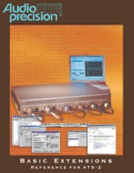
Getting Started with Your 2700 Series Instrument
Getting Started with Your 2700 Series Instrument
Getting Started with Your 2700 Series Instrument

Create successful ePaper yourself
Turn your PDF publications into a flip-book with our unique Google optimized e-Paper software.
Chapter 3: Hardware Overview The SYS-2722 Front Panel<br />
<br />
<br />
<br />
<br />
<br />
<br />
<br />
<br />
<br />
are transmitted on the XLR and BNC “I” and “II” connectors, respectively.<br />
DIGITAL INPUT<br />
In single-connector mode, the instrument receives stereo digital audio<br />
from the XLR “I” connector, the BNC connector, or the optical connector.<br />
In dual-connector mode, channels A and B are received on the XLR<br />
or BNC “I” and “II” connectors, respectively.<br />
ANALOG OUTPUTS<br />
The instrument analog generator outputs (both “A” and “B” channels)<br />
are available as balanced signals on the XLR and dual banana connectors,<br />
and as unbalanced signals on the BNC connectors.<br />
ANALOG INPUTS<br />
The XLR and dual banana (balanced) and the BNC (unbalanced) connectors<br />
(both “A” and “B” channels) are connected to the instrument analyzer<br />
inputs.<br />
SIGNAL MONITOR PORTS<br />
The instrument provides seven signal monitor outputs suitable for audible<br />
monitoring, oscilloscope viewing or other monitoring purposes.<br />
Three of the signals originate <strong>with</strong>in the Analog Analyzer. Four signals<br />
originate in the Digital Analyzer and are converted to the analog domain<br />
for monitoring.<br />
SYNC and TRIGGER PORTS<br />
Two Analog Generator monitor outputs are available, along <strong>with</strong> an Analog<br />
Generator Sync Output and an Analog Generator Trigger Input.<br />
GROUND CONNECTORS<br />
Four banana-jack / bare-wire-terminal ground connectors are provided,<br />
each connected to chassis ground.<br />
HEADPHONE JACK<br />
A 1/4" stereo phone jack connected to the audible monitor output. Inserting<br />
a plug into this jack interrupts the signal to the internal speaker.<br />
VOLUME CONTROL<br />
The volume control adjusts the audio volume of both the internal speaker<br />
and the headphone jack.<br />
POWER SWITCH and INDICATOR<br />
The power switch turns the mains power supply to the instrument hardware<br />
ON ( I ) or OFF ( O ).<br />
See Chapter 4 of the <strong>2700</strong> <strong>Series</strong> User’s Manual for more information about<br />
the instrument inputs and outputs and the panels associated <strong>with</strong> them.<br />
18 <strong>Getting</strong> <strong>Started</strong> <strong>with</strong> <strong>Your</strong> <strong>2700</strong> <strong>Series</strong> <strong>Instrument</strong>