Getting Started with Your 2700 Series Instrument
Getting Started with Your 2700 Series Instrument
Getting Started with Your 2700 Series Instrument

Create successful ePaper yourself
Turn your PDF publications into a flip-book with our unique Google optimized e-Paper software.
The Analog Signal Path Chapter 5: Quick Guides<br />
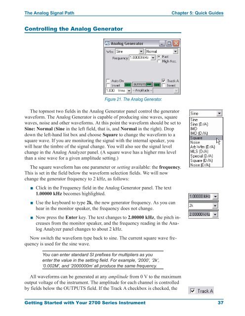
Controlling the Analog Generator<br />
The topmost two fields in the Analog Generator panel control the generator<br />
waveform. The Analog Generator is capable of producing sine waves, square<br />
waves, noise and other waveforms. At this point the waveform should be set to<br />
Sine: Normal (Sine in the left field, that is, and Normal in the right). Drop<br />
down the left-hand list box and choose Square to change the waveform to a<br />
square wave. If you are monitoring the signal <strong>with</strong> the internal speaker, you<br />
will hear the timbre of the signal change. You will also see the signal level<br />
change in the Analog Analyzer panel. (A square wave has a higher rms level<br />
than a sine wave for a given amplitude setting.)<br />
The square waveform has one parameter or setting available: the frequency.<br />
This is set in the field below the waveform selection fields. We will now<br />
change the generator frequency to 2 kHz, as follows:<br />
<br />
<br />
<br />
Figure 21. The Analog Generator.<br />
Click in the Frequency field in the Analog Generator panel. The text<br />
1.00000 kHz becomes highlighted.<br />
Use the keyboard to type 2k, the new generator frequency. As you can<br />
hear in the monitor speaker, the frequency does not change.<br />
Now press the Enter key. The text changes to 2.00000 kHz, the pitch increases<br />
from the monitor speaker, and the frequency reading in the Analog<br />
Analyzer panel changes to about 2 kHz.<br />
Now switch the waveform type back to sine. The current square wave frequency<br />
is used for the sine wave.<br />
You can enter standard SI prefixes for multipliers as you<br />
enter the value in the setting field. For example, ‘2000’, ‘2k’,<br />
‘0.002M’, and ‘2000000m’ all produce the same frequency.<br />
All waveforms can be generated at any amplitude from 0 V to the maximum<br />
output voltage of the instrument. The amplitude for each channel is controlled<br />
by fields below the OUTPUTS field. If the Track A checkbox is checked, the<br />
<strong>Getting</strong> <strong>Started</strong> <strong>with</strong> <strong>Your</strong> <strong>2700</strong> <strong>Series</strong> <strong>Instrument</strong> 37