Getting Started with Your 2700 Series Instrument
Getting Started with Your 2700 Series Instrument
Getting Started with Your 2700 Series Instrument

You also want an ePaper? Increase the reach of your titles
YUMPU automatically turns print PDFs into web optimized ePapers that Google loves.
The Analog Signal Path Chapter 5: Quick Guides<br />
In the default configuration, the Analog Generator panel is set for a 1 Vrms,<br />
1 kHz sine wave, but the analog outputs are disabled. To turn on the outputs,<br />
click the OUTPUTS OFF button near the center of the panel. The button will<br />
turn green, and you will hear relays click in the instrument hardware. The<br />
Level meters on the Analog Analyzer panel will show approximately 1.000 V.<br />
The Level meters show the rms level of the signals at the analog inputs.<br />
The stereo Analog Generator outputs can be individually disabled <strong>with</strong> the<br />
CHA and CHB buttons next to the OUTPUTS field. Click on the CHB button.<br />
The button will turn gray, relays will click in the instrument, and the<br />
Channel B Level meter on the Analog Analyzer panel will indicate a level of<br />
0.000 V.<br />
Now that we’ve successfully routed a signal from the Analog Generator to<br />
the Analog Analyzer, we will perform some basic measurements.<br />
Using the Analog Analyzer<br />
The <strong>2700</strong> series has two independent general-purpose analyzers that can<br />
perform measurements on analog signals. We will be using the Analog Analyzer<br />
for the Quick Guide; the alternative DSP Audio Analyzer is an analysis<br />
tool available on the Digital Analyzer panel that offers similar analysis capabilities.<br />
You can read about the both analyzers in Chapters 8 and 10 of the<br />
<strong>2700</strong> <strong>Series</strong> User’s Manual.<br />
The Analog Analyzer is an analog-domain real-time audio analyzer, implemented<br />
in instrument hardware. It provides continuous readings of signal level<br />
and frequency for both input channels. It also allows you to select a channel<br />
and apply filtering to it, and to measure parameters such as total harmonic distortion,<br />
phase, and so on.<br />
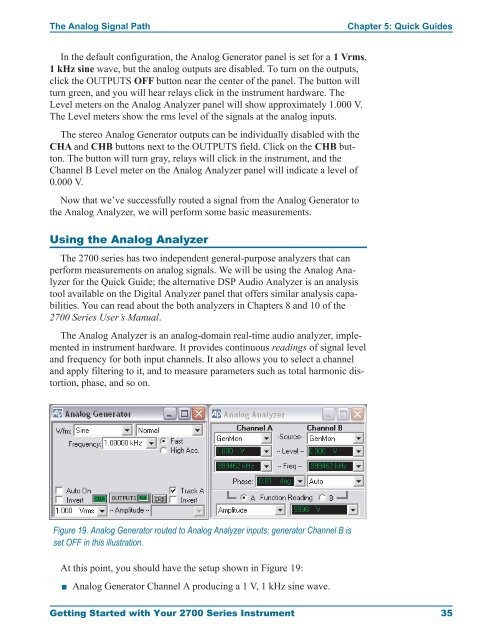
Figure 19. Analog Generator routed to Analog Analyzer inputs; generator Channel B is<br />
set OFF in this illustration.<br />
At this point, you should have the setup shown in Figure 19:<br />
<br />
Analog Generator Channel A producing a1V,1kHzsine wave.<br />
<strong>Getting</strong> <strong>Started</strong> <strong>with</strong> <strong>Your</strong> <strong>2700</strong> <strong>Series</strong> <strong>Instrument</strong> 35