Product Manual (pdf) - TSI
Product Manual (pdf) - TSI
Product Manual (pdf) - TSI

You also want an ePaper? Increase the reach of your titles
YUMPU automatically turns print PDFs into web optimized ePapers that Google loves.
Exposure Monitoring<br />
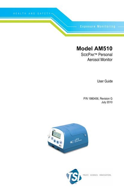
Model AM510<br />
SIDEPAK Personal<br />
Aerosol Monitor<br />
User Guide<br />
P/N 1980456, Revision G<br />
July 2010
Copyright ©<br />
<strong>TSI</strong> Incorporated / Revision G / 2002–2010 / All rights reserved.<br />
Address<br />
<strong>TSI</strong> Incorporated / 500 Cardigan Road / Shoreview, MN 55126 / USA<br />
Fax No.<br />
(651) 490-3824<br />
Limitation of Warranty and Liability (effective July 2000)<br />
Seller warrants the goods sold hereunder, under normal use and service as described in the<br />
operator's manual, shall be free from defects in workmanship and material for twenty-four (24)<br />
months, or the length of time specified in the operator's manual, from the date of shipment to the<br />
customer. This warranty period is inclusive of any statutory warranty. This limited warranty is<br />
subject to the following exclusions:<br />
a. Hot-wire or hot-film sensors used with research anemometers, and certain other components<br />
when indicated in specifications, are warranted for 90 days from the date of shipment.<br />
b. Parts repaired or replaced as a result of repair services are warranted to be free from defects<br />
in workmanship and material, under normal use, for 90 days from the date of shipment.<br />
c. Seller does not provide any warranty on finished goods manufactured by others or on any<br />
fuses, batteries or other consumable materials. Only the original manufacturer's warranty<br />
applies.<br />
d. Unless specifically authorized in a separate writing by Seller, Seller makes no warranty with<br />
respect to, and shall have no liability in connection with, goods which are incorporated into<br />
other products or equipment, or which are modified by any person other than Seller.<br />
The foregoing is IN LIEU OF all other warranties and is subject to the LIMITATIONS stated<br />
herein. NO OTHER EXPRESS OR IMPLIED WARRANTY OF FITNESS FOR<br />
PARTICULAR PURPOSE OR MERCHANTABILITY IS MADE.<br />
TO THE EXTENT PERMITTED BY LAW, THE EXCLUSIVE REMEDY OF THE USER OR<br />
BUYER, AND THE LIMIT OF SELLER'S LIABILITY FOR ANY AND ALL LOSSES,<br />
INJURIES, OR DAMAGES CONCERNING THE GOODS (INCLUDING CLAIMS BASED<br />
ON CONTRACT, NEGLIGENCE, TORT, STRICT LIABILITY OR OTHERWISE) SHALL<br />
BE THE RETURN OF GOODS TO SELLER AND THE REFUND OF THE PURCHASE<br />
PRICE, OR, AT THE OPTION OF SELLER, THE REPAIR OR REPLACEMENT OF THE<br />
GOODS. IN NO EVENT SHALL SELLER BE LIABLE FOR ANY SPECIAL,<br />
CONSEQUENTIAL OR INCIDENTAL DAMAGES. SELLER SHALL NOT BE<br />
RESPONSIBLE FOR INSTALLATION, DISMANTLING OR REINSTALLATION COSTS<br />
OR CHARGES. No Action, regardless of form, may be brought against Seller more than 12<br />
months after a cause of action has accrued. The goods returned under warranty to Seller's<br />
factory shall be at Buyer's risk of loss, and will be returned, if at all, at Seller's risk of loss.<br />
Buyer and all users are deemed to have accepted this LIMITATION OF WARRANTY AND<br />
LIABILITY, which contains the complete and exclusive limited warranty of Seller. This<br />
LIMITATION OF WARRANTY AND LIABILITY may not be amended, modified or its terms<br />
waived, except by writing signed by an Officer of Seller.<br />
Service Policy<br />
Knowing that inoperative or defective instruments are as detrimental to <strong>TSI</strong> as they are to our<br />
customers, our service policy is designed to give prompt attention to any problems. If any<br />
malfunction is discovered, please contact your nearest sales office or representative, or call <strong>TSI</strong>'s<br />
Customer Service department at (800) 874-2811 (USA) or (001 651) 490-2811 (International).
CONTENTS<br />
SAFETY INFORMATION ................................................................... III<br />
SIDEPAK AM510 Rating Label .................................................... iv<br />
Intrinsic Safety Rating Information ................................................ iv<br />
CHAPTER 1 UNPACKING AND PARTS IDENTIFICATION ........... 1<br />
CHAPTER 2 SETTING-UP ................................................................ 5<br />
Supplying Power to the SIDEPAK TM Aerosol Monitor ..................... 5<br />
Battery Information ........................................................................ 6<br />
Installing the NiMH Rechargeable Battery Pack ..................... 6<br />
SidePak NiMH Battery Maintenance ................................... 7<br />
Getting Started ........................................................................ 7<br />
Charging Procedure ................................................................ 7<br />
Storage of NiMH Battery Packs Between Uses ...................... 8<br />
Installing the AA Battery Pack ................................................ 9<br />
Replacing the Cells in the AA Battery Pack .......................... 10<br />
Using the Power Supply ....................................................... 10<br />
Keypad Functions ........................................................................ 12<br />
Setting the Real-Time Clock Using the Keypad .......................... 12<br />
Setting the Date Format: ....................................................... 12<br />
Setting the Current Time: ...................................................... 13<br />
Setting the Current Date: ...................................................... 13<br />
Installing TRAKPRO TM Data Analysis Software ............................. 14<br />
Connecting the SIDEPAK AM510 Personal Aerosol<br />
Monitor to Your Computer for the first time .............................. 14<br />
Connecting the SIDEPAK AM510 Personal Aerosol<br />
Monitor to Your Computer once the drivers are installed ........ 15<br />
CHAPTER 3 OPERATION .............................................................. 17<br />
Overview ...................................................................................... 17<br />
Keypad Functions ........................................................................ 18<br />
Identifying SIDEPAK AM510 Features ...................................... 19<br />
Power Up ..................................................................................... 19<br />
Power Down ................................................................................ 20<br />
Survey Mode ............................................................................... 20<br />
Main Menu ................................................................................... 20<br />
Data Log ............................................................................... 21<br />
Setup Menu ........................................................................... 29<br />
Statistics ................................................................................ 36<br />
Zero Cal ................................................................................ 37<br />
i
CHAPTER 4 MAINTENANCE ......................................................... 39<br />
Maintaining Rechargeable Battery Packs ................................... 39<br />
Charging a NiMH Battery Pack ............................................. 39<br />
Zeroing the AM510 ...................................................................... 41<br />
Using and Maintaining Built-in Impactors .................................... 41<br />
Using and Maintaining the Respirable Cyclone .......................... 44<br />
Cleaning the Cyclone ............................................................ 45<br />
AM510 Field Service Kit .............................................................. 46<br />
CHAPTER 5 TROUBLESHOOTING ............................................... 47<br />
APPENDIX A SPECIFICATIONS .................................................... 51<br />
Battery Information ...................................................................... 53<br />
Typical Battery Life ...................................................................... 54<br />
APPENDIX B CUSTOM CALIBRATIONS ...................................... 55<br />
Determining the Calibration Factor for a Specific Aerosol .......... 55<br />
APPENDIX C CONVERTING STORED DATA TO<br />
CALIBRATED DATA .................................................................. 57<br />
APPENDIX D CSA CERTIFICATE OF COMPLIANCE .................. 59<br />
APPENDIX E AM510 QUICK REFERENCE GUIDE ...................... 63<br />
ii
Safety Information<br />
When operated according to the manufacturer’s instruction, this device is a<br />
Class I laser product as defined by U.S. Department of Health and Human<br />
Services standards under the Radiation Control for Health and Safety Act of<br />
1968.<br />
A certification and identification label like the one shown below is affixed to<br />
each instrument.<br />
Sidepak AM 510 Aerosol Monitor<br />
S/N 02050026 MFD: May 2002<br />
COMPLIES WITH 21 CFR 1040.10 AND 1040.11<br />
<strong>TSI</strong> INC<br />
Shoreview, MN<br />
Made in USA<br />
There are no user-serviceable parts inside this instrument. Performing<br />
services other than those described in this manual may result in exposure to<br />
harmful (visible) laser radiation. A warning label like the one shown below<br />
is affixed to the internal laser device.<br />
!<br />
DANGER: VISIBLE LASER<br />
RADIATION WHEN OPEN. AVOID<br />
DIRECT EXPOSURE TO BEAM<br />
WARNING: NO USER SERVICEABLE<br />
PARTS INSIDE. REFER SERVICING<br />
TO QUALIFIED PERSONNEL.<br />
WARNING<br />
• Use of USB connection to be used only in an area<br />
known to be nonhazardous.<br />
• Battery pack can only be changed/charged in an area<br />
known to be nonhazardous.<br />
iii
SIDEPAK AM510 Rating Label<br />
Intrinsic Safety Rating Information<br />
<strong>TSI</strong> Battery Pack P/Ns 801722, 801724, 801728, or 801729<br />
INTRINSICALLY SAFE CSA<br />
Exia<br />
T2A with 801724 or 801729<br />
T2C with 801722 or 801728<br />
Class I Groups A, B, C, D<br />
Class II Groups E, F, G<br />
Class III<br />
File: 200507<br />
iv
Chapter 1<br />
Unpacking and Parts Identification<br />
Carefully unpack the Model AM510 SIDEPAK Personal Aerosol Monitor<br />
from the shipping container. Use the table below to determine which<br />
components are included with the kit or single unit you purchased. A photo<br />
and description of each item follows the table. If any parts are missing,<br />
contact <strong>TSI</strong> immediately.<br />
AM510 Single-unit Kit with all accessories shown<br />
Item Description Part/Model Reference Picture<br />
AM510 Personal<br />
Aerosol Monitor<br />
AM510-1000<br />
Battery Pack,<br />
1600 mAH<br />
1650 mAH<br />
801723<br />
801724/<br />
801729<br />
SIDEPAK is a trademark of <strong>TSI</strong> Incorporated.<br />
1
Item Description Part/Model Reference Picture<br />
Battery Pack, 2700<br />
mAH<br />
801722/<br />
801728/<br />
801735<br />
AA Battery Pack 801708/<br />
801736<br />
Single Carry Case<br />
11.25” x 9” x 4.25”<br />
3-Unit Carry Case<br />
17” x 12.5” x 4.2”<br />
1319289<br />
1319316<br />
Impactor Kit 801702<br />
Cyclone Kit 801701<br />
2 Chapter 1
Item Description Part/Model Reference Picture<br />
TRAKPRO Software<br />
CD<br />
1090014<br />
Zero Filter 800663<br />
Power Supply 2613210<br />
USB Cable 1303754<br />
Sample Tube 801703<br />
Screwdriver,<br />
Reversible Phillips Flat<br />
3012094<br />
Calibration Certificate N/A<br />
Unpacking and Parts Identification 3
Item Description Part/Model Reference Picture<br />
User Guide 1980456<br />
Quick Reference Card 1980461<br />
SIDEPAK NimH<br />
Battery Maintenance<br />
Card<br />
1980534<br />
4 Chapter 1
Chapter 2<br />
Setting-Up<br />
Supplying Power to the SIDEPAK TM Aerosol Monitor<br />
You must attach a battery pack to the SIDEPAK Personal Aerosol Monitor<br />
Model AM510 prior to use. There are four different <strong>TSI</strong> battery packs<br />
designed for the AM510: 1650 and 2700 mAH rechargeable nickel metal<br />
hydride (NiMH) battery packs, AA battery pack that allows you to use<br />
standard AA-size batteries, and 1600 mAH rechargeable nickel-metal<br />
hydride battery. You may also power the AM510 with the power supply,<br />
with or without a battery pack attached.<br />
The SIDEPAK monitor has a miniature internal backup battery cell that<br />
keeps stored data intact while the unit is turned off. Changing the main<br />
battery pack or disconnecting the power supply/charger will not cause data<br />
to be lost. The backup battery will last for many years. <strong>TSI</strong> will install a new<br />
battery, if necessary, when the unit is returned to the factory for service. The<br />
backup battery is not user-accessible.<br />
The NiMH battery packs are approved and rated intrinsically safe (see<br />
battery information table below). The AA battery pack is not intrinsically<br />
safe. The following battery information table provides the intrinsic safety<br />
rating information.<br />
5
Battery Information<br />
Charge<br />
Battery Option Time 1<br />
1600 mAH NiMH<br />
Pack (P/N 801723)<br />
1650 mAH NiMH<br />
Pack (P/N 801724<br />
or 801729)<br />
2700 mAH NiMH<br />
Pack (P/N 801722<br />
or 801728)<br />
2700 mAH NiMH<br />
Pack (P/N 801735)<br />
6-Cell AA-size Pack<br />
(P/N 801708 or<br />
801736)<br />
6<br />
3.0<br />
hours<br />
3.5<br />
hours<br />
5.5<br />
hours<br />
5.5<br />
hours<br />
Intrinsically<br />
Safe<br />
No N/A<br />
CSA 2<br />
CSA Rating<br />
Exia T2A/<br />
Class I Groups A, B, C, D<br />
Class II Groups E, F, G<br />
Class III<br />
CSA 2<br />
Exia T2C/<br />
Class I Groups A, B, C, D<br />
Class II Groups E, F, G<br />
Class III<br />
No N/A<br />
N/A No N/A<br />
1 Of a full depleted battery<br />
2 All dust plugs and dust gaskets must be installed<br />
Installing the NiMH Rechargeable Battery Pack<br />
Battery packs slide on and off the AM510 in the direction shown below.<br />
There are serrations (teeth) that help hold the battery pack firmly onto<br />
the AM510 body in addition to the two screws. Sliding the battery<br />
on/off requires firm pressure in the proper direction.<br />
!<br />
WARNING<br />
Battery pack can only be changed/charged in an area<br />
known to be nonhazardous.<br />
Battery Pack, 1600 mAH Battery Pack, 2700 mAH<br />
Battery Pack, 1650 mAH<br />
Chapter 2
Place the battery pack on top of the AM510 body and push firmly to<br />
slide it on. Make sure that the front edge of the battery fits under the lip<br />
near the keypad. Once the battery pack is fully seated and the screw<br />
holes are lined up, fasten it in place using the two battery screws<br />
provided.<br />
Note: When installing any of the NiMH battery packs for the first time,<br />
you should charge the battery before using the AM510 to ensure<br />
proper operation. See “Using the Power Supply” later in this<br />
chapter or the Maintenance chapter for charging information.<br />
SidePak NiMH Battery Maintenance<br />
All <strong>TSI</strong> SIDEPAK instruments can be used with all of the SIDEPAK<br />
Nickel Metal Hydride (NiMH) Batteries that incorporate the Smart<br />
Battery Management System technology. These NiMH batteries<br />
provide many advantages over older battery technologies (e.g., NiCad<br />
with their memory issues). However, the NiMH batteries require care<br />
and maintenance to ensure their optimal function.<br />
Getting Started<br />
When you first receive a SIDEPAK instrument with a NiMH battery<br />
you will need to charge and discharge the unit several times (typically 3<br />
charges and 2 full discharges is enough to get good run time<br />
information) in order for the Smart Battery Management System<br />
technology to optimize its performance. Each time you initiate the<br />
charging cycle the battery will fully charge. However, the battery’s run<br />
time information will become more accurate after each successive<br />
charge and discharge cycle. Simply put, the more you use the<br />
SIDEPAK instrument with the NiMH battery, the smarter it will get<br />
and the more accurate the run time information will be. The initial<br />
charging procedure is outlined below:<br />
Charging Procedure<br />
• Charge #1<br />
• Discharge #1<br />
• Charge #2<br />
• Discharge #2<br />
• Charge #3<br />
Smart Battery Management System technology charging is now<br />
complete and optimized.<br />
Smart Battery Management System is a trademark of <strong>TSI</strong> Incorporated.<br />
Setting-Up 7
8<br />
For additional battery charging instructions see Chapter 4,<br />
“Maintenance; Charging a NiMH Battery Pack” found in all of the<br />
SIDEPAK instrument User Guides.<br />
To discharge the various SIDEPAK instruments use the following<br />
procedure to minimize the time to discharge the battery:<br />
• Go to the MAIN MENU Setup Adjust Flow <br />
FLOWRATE 150 Range (adjust flow setting via ▼▲ keys)<br />
with no sampling train attached in open flow mode and wait for<br />
the battery to run down and the instrument to shut off. Then,<br />
recharge the battery.<br />
Note: It is always recommended that you charge your SIDEPAK<br />
instrument with NiMH battery pack after each use to<br />
optimize and maintain the Smart Battery Management<br />
System technology between uses.<br />
Battery life indicator is not considered accurate until<br />
battery has been optimized.<br />
1600 mAH battery display will not indicate 100% on the<br />
first charge.<br />
Storage of NiMH Battery Packs Between Uses<br />
Remember that all rechargeable battery technologies (NiMH, NiCad,<br />
LiIon, Lead Acid, etc.) will lose charge over time due to charge<br />
dissipation. If you store your SIDEPAK instruments between uses for<br />
more than 2 months (60 days) make sure that it is completely charged<br />
before doing so. Storage of exhausted batteries (from not recharging and<br />
storing after use), or from extended storage intervals exceeding 2<br />
months (60 days), may result in the NiMH batteries becoming unusable<br />
over time. Deep battery discharge is possible if this occurs and it may<br />
not be possible to recondition the NiMH battery once this has happened<br />
and this is not covered under warranty.<br />
During storage it is recommended that you discharge then charge your<br />
SIDEPAK instruments every 4 to 6 weeks to ensure that the NiMH<br />
battery is maintained and charged and the Smart Battery Management<br />
System is optimized. Simply follow the discharging and charging<br />
procedure described above or from any of the SIDEPAK instrument<br />
User Guides in Chapter 4, “Maintenance.” Not following this<br />
recommendation could lead to requiring the “Getting Started” procedure<br />
to be repeated again or battery replacement (not covered under<br />
warranty) due to deep battery discharge.<br />
Chapter 2
Installing the AA Battery Pack<br />
Note: Alkaline battery cells are included with the AA battery pack. <strong>TSI</strong><br />
recommends size AA alkaline batteries for best performance.<br />
The power supply may be used to power the AM510 while the<br />
AA battery pack is attached to the AM510 body. The AM510 will<br />
sense the presence of the AA battery pack and automatically<br />
disable the charging function.<br />
AA-size rechargeable batteries may be used in the AA battery<br />
pack; however they cannot be recharged by the SIDEPAK<br />
aerosol monitor charging system. An external charger will be<br />
needed. Instrument run-time with AA-size rechargeable cells<br />
may be unacceptably short (see "Typical Battery Life”<br />
specifications).<br />
The AA battery pack opens into two pieces.<br />
Install six AA-size battery cells. Make sure the cells are installed in the<br />
proper direction by matching the polarity markings on the cell holder<br />
with the markings on the battery cells.<br />
Attach the battery cover by carefully placing it in the forward position<br />
shown. Slide the cover forward, and under the lip on the instrument.<br />
Fasten it in place with two screws.<br />
Setting-Up 9
10<br />
Replacing the Cells in the AA Battery Pack<br />
To replace the disposable cells in the AA battery pack, remove the<br />
battery pack. Loosen the two side screws about half way. Slide the<br />
cover back until it is free of the screws, then lift up and remove.<br />
Open the battery pack. Remove the old batteries and dispose of them<br />
according to local jurisdiction. It may be helpful to use the flat-bladed<br />
screwdriver to gently pry up the positive (+) end of the battery cells.<br />
Close the battery pack. Slide the battery pack into position placing the<br />
tab in place first. Push the battery pack snuggly into position and secure<br />
with the two screws on the sides.<br />
Using the Power Supply<br />
The power supply allows you to power the SIDEPAK monitor from an<br />
AC wall outlet, or to charge any of the <strong>TSI</strong> NiMH battery packs.<br />
Connect the power supply to an AC wall outlet and plug the other end<br />
into the power port on the side of the AM510.<br />
!<br />
Caution<br />
Many power supplies look alike. Make certain you are<br />
using the proper power supply for the AM510. Using the<br />
wrong power supply may permanently damage the<br />
instrument and void the warranty.<br />
Chapter 2
!<br />
WARNING<br />
Use of USB connection to be used only in an area known<br />
to be nonhazardous.<br />
The power supply cannot run the SIDEPAK monitor and charge the<br />
battery at the same time. Make sure the instrument is turned off to<br />
initiate the charging cycle. If the display does not show CHARGING<br />
BATTERY, it is not charging.<br />
When the power supply is first plugged into the AM510, the display<br />
will first show the message DETECTING BATTERY TYPE. If any of<br />
the <strong>TSI</strong> NiMH battery packs are detected, the display will show<br />
CHARGING BATTERY. Once the battery is fully charged, the display<br />
will show CHARGING COMPLETE. The instrument may be turned<br />
on at any time during or after the charging process by pressing the<br />
PAGE key. Turning the instrument on during the charging process will<br />
abort charging.<br />
If the AA battery pack is detected (regardless of installed cell type) or<br />
there is no battery pack at all, the display will show CHARGING OFF<br />
after 30 seconds. Press the PAGE key to turn the instrument on or off at<br />
any time.<br />
Setting-Up 11
Keypad Functions<br />
To turn the instrument ON, press the PAGE key.<br />
The model number, serial number, firmware revision and remaining battery<br />
charge are displayed for a few seconds before entering Survey Mode.<br />
12<br />
To turn the instrument OFF, press and hold the PAGE<br />
key for three (3) seconds.<br />
Release when the countdown reaches "0 SECONDS."<br />
Use the PAGE key to go back to the previous menu.<br />
Use the ↵ key to execute selected menu options and<br />
confirm changes.<br />
Use the ▲▼ arrow keys to scroll through vertical<br />
menus and to change numeric values.<br />
To toggle between an unlocked and locked keypad<br />
(tamper prevention), press and hold the ▲ key and<br />
press ↵. When the keypad is locked, the display shows<br />
KEYPAD LOCK.<br />
Setting the Real-Time Clock Using the Keypad<br />
Setting the Date Format:<br />
The date format is user-selectable. The formats available are:<br />
• yyyy/mm/dd (default)<br />
• mm/dd/yyyy<br />
• dd/mm/yyyy<br />
where yyyy is the 4-digit year, mm is the 2-digit month, and dd is the<br />
2-digit day of month.<br />
1. If necessary, turn the SIDEPAK AM510 on by pressing the PAGE<br />
key.<br />
Chapter 2
2. Press the PAGE key to access the Main Menu.<br />
3. Under MAIN MENU, select Setup with the ▲ ▼ keys and press<br />
↵.<br />
4. Under SETUP MENU, select Time/Date with the ▲ ▼ keys and<br />
press ↵.<br />
5. Under TIME/DATE, select Format with the ▲ ▼ keys and press<br />
↵.<br />
6. Use the ▲ ▼ keys to select the desired format, then press ↵.<br />
7. Press the PAGE key to return to Survey Mode.<br />
Setting the Current Time:<br />
1. If necessary, turn the SIDEPAK AM510 on by pressing the PAGE<br />
key.<br />
2. Press the PAGE key to access the Main Menu.<br />
3. Under MAIN MENU, select Setup with the ▲ ▼ keys and press<br />
↵.<br />
4. Under SETUP MENU, select Time/Date with the ▲ ▼ keys and<br />
press ↵.<br />
5. Under the TIME/DATE menu, use the ▲ ▼ keys to select Time.<br />
Set the correct hour in 24-hour format (e.g. 3 p.m. = 15 hours) then<br />
press ↵. Use the ▲ ▼ keys to set the correct minutes and press ↵.<br />
6. Press the PAGE key to return to Survey Mode.<br />
Setting the Current Date:<br />
1. If necessary, turn the SIDEPAK AM510 on by pressing the PAGE<br />
key.<br />
2. Press the PAGE key to access the Main Menu.<br />
3. Under MAIN MENU, select Setup with the ▲ ▼ keys and press<br />
↵.<br />
4. Under SETUP MENU, select Time/Date with the ▲ ▼ keys and<br />
press ↵.<br />
5. Under the TIME/DATE menu, use the ▲ ▼ keys to select Date.<br />
Use the ▲ ▼ keys to set the correct year and press ↵. Use the ▲<br />
▼ keys to set the correct month and press ↵. Use the ▲ ▼ keys to<br />
select the correct day and press ↵ (order will vary depending on<br />
selected date format).<br />
Setting-Up 13
14<br />
6. Press the PAGE key to return to Survey Mode.<br />
Installing TRAKPRO TM Data Analysis Software<br />
TRAKPRO Data Analysis Software can preprogram the SIDEPAK<br />
AM510, download data, view and create raw data and statistical reports,<br />
create graphs, and combine graphs with data from other <strong>TSI</strong> instruments that<br />
use TRAKPRO software. The following sections describe how to install the<br />
software and set up the computer.<br />
Note: To use TRAKPRO software with the SIDEPAK AM510, the PC<br />
must be running Microsoft Windows ®<br />
and the computer must have<br />
an available Universal Serial Bus (USB) port.<br />
1. Insert the TRAKPRO software CD into the CD-ROM drive. The install<br />
screen starts automatically.<br />
Note: If the software does not start automatically after a few minutes,<br />
manually run the program listed on the label of the CD using<br />
the Run command on the Windows Start Menu.<br />
2. Follow the directions to install TRAKPRO software.<br />
TRAKPRO software contains a comprehensive installation guide. It is<br />
recommended to print out this prior to starting the TRAKPRO software<br />
installation on your computer, so it may be consulted during the installation.<br />
The TRAKPRO software manual is located in the “Help” file in<br />
TRAKPRO software. There is no separately printed TRAKPRO software<br />
manual.<br />
Connecting the SIDEPAK AM510 Personal Aerosol Monitor to<br />
Your Computer for the first time<br />
Most SIDEPAK AM510 kits include a USB (Universal Serial Bus) cable<br />
that connects between the instrument and an available USB port on your PC.<br />
1. Locate an available USB port on your computer.<br />
2. Connect the larger end of the USB cable to the USB port.<br />
3. Turn the SIDEPAK AM510 on.<br />
4. Connect the small end of the USB cable to the USB port on the<br />
SIDEPAK AM510.<br />
5. The first time you plug in the SIDEPAK AM510, the Windows utility<br />
for installing new hardware will launch automatically. Follow the<br />
onscreen instructions for installing the drivers. Refer to the software<br />
installation guide as needed.<br />
® Microsoft and Windows are registered trademarks of Microsoft Corporation.<br />
Chapter 2
6. After the New Hardware utility has finished, complete the installation of<br />
TRAKPRO TM software.<br />
Connecting the SIDEPAK AM510 Personal Aerosol Monitor to<br />
Your Computer once the drivers are installed<br />
After you have installed the drivers for the SIDEPAK AM510, each<br />
subsequent time you plug-in the instrument, the instrument will be<br />
automatically detected. Your computer will load the proper driver files to<br />
communicate with the SIDEPAK monitor. If you have difficulty<br />
communicating with the instrument, please review the following<br />
troubleshooting steps:<br />
Symptom Cause Solution<br />
Receive the following<br />
error message:<br />
Receive the following<br />
error message(s):<br />
The SIDEPAK<br />
AM510 drivers take<br />
approximately 20<br />
seconds to “load,”<br />
each time the<br />
instrument is plugged<br />
in. If you attempt to<br />
communicate with the<br />
instrument during this<br />
period, you will receive<br />
an error.<br />
1. The Software<br />
Configuration is not<br />
set properly to<br />
SIDEPAK<br />
Aerosol Monitor.<br />
2. Or the Auto-<br />
Configuration is<br />
turned off.<br />
3. Or the instrument is<br />
turned off (powered<br />
down).<br />
4. Or the instrument is<br />
not attached to the<br />
USB cable, either at<br />
the instrument side<br />
or computer side.<br />
Wait approximately<br />
30 seconds, after<br />
plugging in the USB<br />
cable, before you<br />
attempt to<br />
communicate with<br />
the instrument.<br />
1. Select Option:<br />
Software<br />
Configure:<br />
SIDEPAK Aerosol<br />
Monitor.<br />
2. Or select the<br />
SIDEPAK Aerosol<br />
Monitor from the<br />
drop-down list on<br />
the menu bar.<br />
3. Or Check (turnon)<br />
the Autoconfiguration,<br />
under Options.<br />
4. Or turn on the<br />
instrument.<br />
5. Or attach USB<br />
cable.<br />
Setting-Up 15
16<br />
Symptom Cause Solution<br />
Receive the following error message:<br />
1. The instrument is<br />
not in the Survey<br />
Mode (it is logging<br />
data, the display is<br />
set to one of the<br />
Setup screens,<br />
etc.). It will not<br />
communicate<br />
properly in this<br />
case.<br />
1. Return to the<br />
Survey Mode,<br />
before attempting<br />
to communicate<br />
with the<br />
instrument.<br />
Note: It may appear that TRAKPRO software has found the SIDEPAK<br />
instrument on a COM port rather than a USB port. This is normal<br />
and will work fine.<br />
Chapter 2
Chapter 3<br />
Operation<br />
Overview<br />
The SIDEPAK TM Personal Aerosol Monitor is a miniature battery-operated<br />
laser photometer that measures airborne particle mass-concentration in units<br />
of milligrams per cubic meter (mg/m 3 ). The built in sampling pump flow rate<br />
is user-adjustable, allowing you to attach a wide variety of inlet conditioners<br />
to sample from the worker’s breathing zone or other locations. The rugged<br />
belt-mountable unit is small, quiet, and lightweight, minimizing interference<br />
and discomfort for the wearer. The 12-character x 2 line LCD displays<br />
aerosol concentration and 8-hour TWA (time-weighted average) in realtime.<br />
Information can be stored and later downloaded via a Windows ® based<br />
PC using the enclosed TRAKPRO TM software and USB (Universal Serial Bus)<br />
communications cable.<br />
17
Keypad Functions<br />
To turn the instrument ON, press the PAGE key.<br />
The model number, serial number, firmware revision and % battery charge<br />
are displayed for a few seconds before entering Survey Mode.<br />
18<br />
To turn the instrument OFF, press and hold the PAGE<br />
key for three (3) seconds.<br />
Release when the countdown reaches "0 SECONDS."<br />
Use the PAGE key to go back to the previous menu.<br />
Use the ↵ key to execute selected menu options and<br />
confirm changes.<br />
Use the ▲▼ arrow keys to scroll through vertical<br />
menus and to change numeric values.<br />
To toggle between an unlocked and locked keypad<br />
(tamper prevention), press and hold the ▲ key and<br />
press ↵. When the keypad is locked, the display shows<br />
KEYPAD LOCK.<br />
Chapter 3
Identifying SIDEPAK AM510 Features<br />
USB Port Use the Universal Serial Bus (USB) port and USB<br />
cable to connect the SIDEPAK AM510 to an<br />
available USB port on your computer. The connector<br />
on the AM510 is a type USB-Mini-B socket.<br />
Power Port Connect the 9 VDC power supply to this port to<br />
charge <strong>TSI</strong> NiMH battery packs or to power the<br />
instrument at any time. Many power supplies look<br />
alike; make certain you use the right power supply to<br />
prevent damage.<br />
Exhaust Port Air drawn though the instrument exits here.<br />
Inlet Interchangeable inlet. You can install the standard<br />
inlet or one of three impactors provided with<br />
SIDEPAK AM510 Kits.<br />
Battery Screw Remove these two screws to remove the battery pack.<br />
Power Up<br />
Turn the SIDEPAK AM510 on by pressing the PAGE key. The AM510<br />
will display the model number, serial number, percent memory remaining<br />
and firmware version. It will now immediately go into Warmup Mode<br />
during which time the pump is reaching the flow rate setpoint. During this<br />
time in Warmup Mode while the pump is in the process of reaching the flow<br />
rate setpoint, if the AM510 is under battery power, Battery Life Remaining<br />
will change (decrease) to account for the increasing current consumption of<br />
the pump, finally reaching a steady-state when the desired flow rate setpoint<br />
is achieved. After the pump has achieved the flow rate setpoint, it will go<br />
into Survey Mode.<br />
Operation 19
Power Down<br />
To turn the SIDEPAK AM510 off, press the PAGE key until the instrument<br />
displays SURVEY MODE. Then, press and hold the PAGE key. Release<br />
the key after the 3-second countdown reaches zero.<br />
Survey Mode<br />
When the SIDEPAK monitor is first turned on, it will always go into<br />
Survey Mode. In Survey Mode the instrument displays real-time aerosol<br />
concentration readings in units of milligrams per cubic meter (mg/m 3 ). Data<br />
logging is not enabled during Survey Mode.<br />
While in Survey Mode, use the ▲ ▼ keys to view the:<br />
• Percentage of memory available<br />
• Battery life remaining displayed in minutes<br />
• Time of day<br />
• Today's Date<br />
• Current calibration factor<br />
20<br />
Note: While in the Survey Mode, if you view another display screen and<br />
leave the display in this location, the AM510 display returns to<br />
the next higher level menu after 30 seconds. Eventually, it returns<br />
to the Survey Mode, showing real-time aerosol concentrations.<br />
Main Menu<br />
When in the Survey Mode, you can access the Main Menu by pressing the<br />
PAGE key. Use the ▲ ▼ keys to select one of the following sub menus:<br />
• Data Log<br />
• Setup<br />
• Statistics<br />
• Zero Cal<br />
Refer to the corresponding section below for details on each sub menu.<br />
Chapter 3
Data Log<br />
The Data Log sub menu contains three options:<br />
• Run <strong>Manual</strong><br />
• Run Prog 1<br />
• Run Prog 2<br />
Use the ▲ ▼ keys to make a selection, and press ↵ to accept.<br />
Operation 21
22<br />
Run <strong>Manual</strong> immediately starts a data logging session (called a<br />
"Test").<br />
Press ↵ or PAGE to stop a test in progress. The AM510 will ask you to<br />
confirm that you want to stop the test or not, while data logging<br />
continues. If you choose to continue (Return) by pressing the PAGE<br />
key, there will be no break in the data.<br />
While running a manual test, the display shows LOGGING DATA as<br />
well as the last data value recorded. <strong>Manual</strong> tests use the logging<br />
interval defined in Log Interval under the Setup Menu.<br />
Each test you run is assigned a sequential number (e.g., TEST#1,<br />
TEST#2, … TEST#100) until memory is used up or cleared.<br />
When a test is stopped, the display immediately switches to the<br />
Statistics Menu where you can view the following statistics for any<br />
stored test:<br />
• Maximum reading<br />
• Minimum reading<br />
• Average reading<br />
• 8-hour TWA<br />
• Time (duration of test)<br />
First, select the test to view with the ▲ ▼ keys and press ↵. Now, you<br />
can page through the available statistics using the keys. Initially, the test<br />
you just completed is offered. You can view test statistics any time you<br />
are not actively data logging by selecting Statistics under the Main<br />
Menu.<br />
Run Prog 1 and Run Prog 2 allow you to execute a data logging test<br />
that was preprogrammed using TRAKPRO TM Data Analysis Software.<br />
Preprogramming allows a great deal of flexibility that is not available<br />
with manual logging such as predefined start and stop times, logging<br />
intervals, calibration factors, and more. See “Programming Prog 1 and<br />
Prog 2 with TRAKPRO Software” later in this chapter.<br />
During data logging, use the ▲ ▼ keys to view:<br />
• Battery life remaining displayed in minutes<br />
• 8-hour TWA<br />
• Elapsed time<br />
• Current time and date<br />
• Log interval<br />
Chapter 3
If 30 seconds elapse without a key being pressed, the display reverts<br />
back to LOGGING DATA and shows the last data value recorded.<br />
To stop a test, press the ↵ or PAGE key. The AM510 will ask you to<br />
confirm that you want to stop the test or not, while data logging<br />
continues. If you choose to continue (Return), there will be no break in<br />
the data.<br />
If you stop a test in progress, the AM510 will display Data Logging<br />
Stop Data Saved and switch to the Statistics Menu so you can view<br />
the results of that test.<br />
If you stop a test before any data points have been recorded, the display<br />
will show Data Logging Aborted and wait for you to acknowledge by<br />
pressing ↵. It will then return to Survey Mode. An example of when this<br />
may happen is if the logging interval is set to 1 minute and the test is<br />
stopped before the first data point is recorded.<br />
Programming Prog 1 and Prog 2 with TRAKPRO<br />
Software<br />
Use Prog 1 or Prog 2 modes for unattended recording and setting<br />
user protocols. With Prog 1 and Prog 2 modes you can set the start<br />
date, start time, test length, logging interval, number of tests and the<br />
time delay between tests. All or selected parameters can be set.<br />
To program a protocol for Prog 1 or Prog 2 mode:<br />
1. Make sure the SIDEPAK monitor is connected to the<br />
computer and turned on.<br />
2. Select Logging Setup from the Instrument Setup menu.<br />
TRAKPRO software retrieves the current settings for Prog 1<br />
and Prog 2 modes from the SIDEPAK monitor and displays<br />
them in the following dialog:<br />
Operation 23
24<br />
The following table summarizes the information displayed in the<br />
SIDEPAK Logging Protocols dialog box:<br />
Serial Number Displays the serial number of the SIDEPAK<br />
monitor currently connected to computer.<br />
Number of tests<br />
logged<br />
Available<br />
Memory (%)<br />
Displays the number of tests currently stored<br />
in the SIDEPAK monitor.<br />
Displays the percent of available memory in<br />
the SIDEPAK monitor.<br />
Prog 1 and Prog 2 Mode Protocols<br />
Start Date Displays the start date for Prog 1 and Prog 2<br />
modes.<br />
Start Time Displays the start time for Prog 1 and Prog 2<br />
modes.<br />
Log interval Displays the log interval for Prog 1 and Prog 2<br />
modes.<br />
Test length Displays the test length for Prog 1 and Prog 2<br />
modes.<br />
Number of tests Displays the number of times to repeat the<br />
defined test, for Prog 1 and Prog 2 modes.<br />
Time between<br />
tests<br />
Displays the time between repeated tests for<br />
Prog 1 and Prog 2 modes.<br />
Chapter 3
Prog 1 and Prog 2 Mode Protocols<br />
Percent<br />
memory<br />
required.<br />
Displays the percent of SIDEPAK memory<br />
required to perform a Prog 1 or a Prog 2 mode<br />
sample. To store the results of a Prog 1 or<br />
Prog 2 mode sample, the Available Memory<br />
must be equal to or greater than the Percent<br />
memory required.<br />
3. Enter the following for Prog 1 and Prog 2 modes:<br />
Start Date<br />
Start Time<br />
Enter the date and time to begin the sample:<br />
• If you enter a blank for a start date, the<br />
sample begins whenever the specified start<br />
time occurs.<br />
• If you enter a blank for the start time, both<br />
start date and start time are ignored, and<br />
the sample begins when the operator<br />
manually starts the sample.<br />
Log interval Enter the log interval to use for the test.<br />
Test length Enter the length for the sample:<br />
• If you enter a value, the instrument<br />
automatically turns off when the last test is<br />
complete.<br />
• If you enter a blank, you must manually<br />
stop the sample.<br />
Number of tests Enter the number of tests to perform. These<br />
tests will happen sequentially, with the Time<br />
between tests spaced in between each<br />
repetition.<br />
Time between<br />
tests<br />
If you have specified more than one Number<br />
of tests, enter the time between tests. If you<br />
enter 0 or blank, the next test is started<br />
immediately after the last test is complete.<br />
Operation 25
26<br />
While you are entering values for Prog 1 and Prog 2 modes,<br />
the Percent Memory Required is dynamically updated to<br />
show the amount of SIDEPAK memory required to take the<br />
programmed sample. If the protocol you have defined requires<br />
more than 100% of memory (or more than the available<br />
memory), you can decrease the amount of memory required by<br />
manipulating the following protocol parameters:<br />
• Increase the logging interval.<br />
• Decrease the time (length) for the test.<br />
• Decrease the number of tests.<br />
Note: For proper operation, the settings for each Prog mode<br />
must not require more than 100% of the logger<br />
memory. If the Percent memory required is greater<br />
than the Available memory, the logging instrument<br />
automatically stops the test when memory is full.<br />
4. When you have finished defining the parameters for Prog 1 and<br />
Prog 2 modes, select Send. The software confirms that the<br />
instrument was programmed properly.<br />
5. You can now disconnect the SIDEPAK monitor and cable<br />
from the computer.<br />
Example Setup for Prog 1 and Prog 2 Modes Using<br />
TRAKPRO Software<br />
The following example describes how to program Prog 1 or Prog 2<br />
mode tests.<br />
The protocol for Prog 1 is set to take unattended aerosol readings<br />
for one day, 09/01/2008. The logging sample begins at 8:00 a.m.<br />
and continues for eight hours.<br />
The protocol for Prog 2 is set up to take unattended aerosol<br />
readings for two days, beginning on 09/01/2008. Logging begins at<br />
8:00 a.m. and continues for eight hours. The instrument is off for 16<br />
hours, and then repeats the eight-hour test on the following day.<br />
The following graphic shows the dialog box displayed in the<br />
TRAKPRO software, with these particular logging parameters.<br />
Chapter 3
To program the above example, do the following:<br />
1. Make sure the SIDEPAK monitor is connected to the<br />
computer and turned on.<br />
2. Select Logging Setup from the Instrument Setup menu.<br />
TRAKPRO TM software retrieves the current settings for Prog 1<br />
and Prog 2 modes from the SIDEPAK monitor and displays<br />
them in the dialog shown above.<br />
3. Enter the following for Prog 1 and Prog 2:<br />
Setting Prog 1 Prog 2<br />
Start Date 09/01/2008 09/01/2008<br />
Start Time 08:00 08:00<br />
Log interval 01:00 05:00<br />
Test length 00:08:00 00:08:00<br />
Number of tests 1 2<br />
Time between<br />
tests<br />
00:00:00 00:16:00<br />
4. Select Send. The SIDEPAK monitor is programmed for the<br />
Prog 1 and Prog 2 protocols.<br />
5. Note that the Prog 1 test requires 1% of the available memory<br />
and Prog 2 requires less than 1% of the memory. A total of<br />
100% of the memory is available for use.<br />
Operation 27
28<br />
6. You can now disconnect your SIDEPAK monitor from the<br />
computer.<br />
After programming the SIDEPAK monitor with TRAKPRO Data<br />
Analysis Ssoftware, attach the SIDEPAK monitor to the worker (or<br />
location) and turn it on. Put it into Prog 1 or Prog 2 mode<br />
(whichever you want) using the keypad.<br />
1. From SURVEY MODE, press PAGE to access MAIN MENU.<br />
2. Scroll to Data Log and press ↵.<br />
3. Scroll to Run Prog 1 (or Run Prog 2) and press ↵.<br />
4. If desired, lock the keypad to prevent tampering. Press and<br />
hold the ▲ key, then press ↵. Repeat to unlock.<br />
Things You Should Know About Using Prog 1 and Prog 2<br />
Modes<br />
• If you press the PAGE or ↵ key during programmed operation,<br />
the instrument responds with a message, asking you to confirm<br />
your choice to end the program (unless the keypad is locked).<br />
• If the programmed start date has already passed, the program<br />
will not execute. The instrument responds with a message<br />
indicating INVALID PRGM; START DATE.<br />
• It is always best to enter both a start time and start date!<br />
However, setting the start time but no start date causes the<br />
SIDEPAK monitor to start at the specified time regardless of<br />
the date. The instrument may not shut down prior to beginning<br />
logging.<br />
• If no start time is set, the SIDEPAK monitor begins sampling<br />
immediately after the program is selected and the ↵ key is<br />
pressed.<br />
• If no test length is set, the SIDEPAK monitor takes samples<br />
continuously until the program is deliberately terminated, using<br />
the ↵ key, or until memory is full.<br />
• When a preprogrammed test ends, the SIDEPAK monitor<br />
automatically shuts off.<br />
Chapter 3
Setup Menu<br />
When in Survey Mode, you can access the Setup Menu by pressing the<br />
PAGE key to reach the Main Menu, then use the ▲ ▼ keys to select<br />
Setup Menu and press ↵.<br />
The Setup Menu provides access to the following items. Use the ▲ ▼<br />
keys to select the item you wish to access and press ↵. Each selection is<br />
described in detail below.<br />
• Time/Date<br />
• Clear Memory<br />
• Log Interval<br />
• Time Constnt<br />
• Cal Factor<br />
• Adjust Flow<br />
Time/Date<br />
See “Setting the Real-Time Clock Using the Keypad” in the Setup<br />
chapter for instructions on setting the real-time clock using the<br />
SIDEPAK keypad.<br />
Setting the Real-Time Clock Using TRAKPRO Software<br />
1. Make sure the SIDEPAK monitor is connected to the<br />
computer and turned on.<br />
2. In TRAKPRO Software, select Parameters, then Clock from<br />
the Instrument Setup menu. TRAKPRO TM software retrieves<br />
the current date and time settings from the SIDEPAK monitor.<br />
3. The system date and time (from the computer) can be<br />
transferred to the SIDEPAK monitor by clicking the correct<br />
buttons on the screen. A drop-down calendar allows you to<br />
select the date. Alternately, the date and time can be manually<br />
typed into the dialog box.<br />
4. Select Send to reprogram the real-time clock inside the<br />
SIDEPAK monitor.<br />
Clear Memory<br />
This function will permanently erase all logged data and associated<br />
statistics stored in memory. It will not affect the Prog-1 and Prog-2<br />
stored programs, stored Cal Factors, or any other settings.<br />
1. After selecting Clear Memory under the Setup Menu, the<br />
display will show Press Enter = Clr Memory. Press ↵.<br />
Operation 29
30<br />
2. You will be prompted to confirm your intention with the<br />
display Confirm Clr Press Enter. Press ↵.<br />
3. The display will show Memory Cleared for a few seconds<br />
and will go back to the Setup Menu.<br />
Log Interval<br />
The log interval is the time interval used between recorded data<br />
points during Run <strong>Manual</strong> logging operations (log intervals for<br />
Prog-1 and Prog-2 are set using TRAKPRO TM Software). For<br />
example, if the log interval is set to 30 seconds, a data point is<br />
stored to memory once every 30 seconds. One reason you might<br />
want to use a longer log interval is to conserve memory.<br />
The SIDEPAK AM510 always makes a measurement once every<br />
second regardless of the log interval selected. Using a log interval<br />
greater than one second results in stored data points that are<br />
averages of the 1-second readings. For example, a 10-second log<br />
interval will result in one stored data point every 10 seconds. Each<br />
of those data points will represent the computed average of ten, 1second<br />
readings.<br />
Do not confuse log intervals with time constants. Log intervals only<br />
affect recorded readings. Time constants only affect the AM510<br />
LCD display.<br />
There are five preprogrammed choices for log intervals. If<br />
necessary, the list of available log intervals may be permanently<br />
altered using TRAKPRO TM Software.<br />
After selecting Log Interval from the Setup Menu, the display will<br />
show LOG INTVLx where "x" is a number from 1 to 5. This is the<br />
currently selected log interval. The value of that log interval is<br />
shown on the second line.<br />
Use the ▲ ▼ keys to scroll through the available log intervals.<br />
Press ↵ when the interval you wish to use is displayed. The factorypreset<br />
choices are:<br />
• LOG INTVL1: 1 sec<br />
• LOG INTVL2: 10 sec<br />
• LOG INTVL3: 30 sec<br />
• LOG INTVL4: 1 min<br />
• LOG INTVL5: 5 min<br />
Chapter 3
Editing the List of Log Intervals with TRAKPRO Software<br />
To program the list of log intervals available for Run <strong>Manual</strong><br />
Mode:<br />
1. Start TRAKPRO TM Software and make sure the SIDEPAK<br />
monitor is connected to the computer and turned on.<br />
2. In TRAKPRO TM , select Parameters, then Logging Intervals<br />
from the Instrument Setup menu. TRAKPRO TM software<br />
retrieves the current list of log intervals from the SIDEPAK<br />
monitor and displays them.<br />
3. Enter a value for each of the five log intervals (the range is<br />
from 1 second to 59 minutes and 59 seconds).<br />
4. Select Send. The SIDEPAK monitor is now reprogrammed to<br />
offer the log intervals you have specified.<br />
5. Use the SIDEPAK monitor keypad to make sure the log<br />
interval is set to the value you want to use.<br />
Time Constant<br />
The time constant is used to dampen fluctuations in the displayed<br />
readings, to make them easier to read. The time constant setting<br />
affects values shown on the AM510 LCD display only.<br />
The SIDEPAK AM510 always makes a measurement once every<br />
second and updates the display every second regardless of the time<br />
constant selected. Using a time constant greater than one second<br />
results in displayed readings that are averages of the 1-second<br />
readings. For example, a 10-second time constant will cause the<br />
display to show an average of the most recent ten 1-second<br />
readings. In other words it is a 10-second "moving average,"<br />
updated every second.<br />
Do not confuse time constant with logging intervals. Time<br />
constants only affect the AM510 display. Log intervals only affect<br />
recorded readings.<br />
There are five preprogrammed choices for time constants. If<br />
necessary, the list of available time constants may be permanently<br />
altered using TRAKPRO TM Software.<br />
After selecting Time Constant from the Setup Menu, the display<br />
will show TIME CONSTx where "x" is a number from 1 to 5. This<br />
is the currently active time constant. The value of that time constant<br />
is shown on the second line.<br />
Operation 31
32<br />
Use the ▲ ▼ keys to scroll through the available time constants.<br />
Press ↵ when the time constant you wish to use is displayed. The<br />
factory-preset choices are:<br />
• TIME CONST 1: 1 sec<br />
• TIME CONST 2: 5 sec<br />
• TIME CONST 3: 10 sec<br />
• TIME CONST 4: 15 sec<br />
• TIME CONST 5: 30 sec<br />
Editing the List of Time Constants Using TRAKPRO<br />
software<br />
To program the list of time constants using TRAKPRO TM Data<br />
Analysis Software:<br />
1. Make sure the SIDEPAK monitor is connected to the<br />
computer and turned on.<br />
2. Select Parameters, then Time Constants from the<br />
Instrument Setup menu. TRAKPRO TM software retrieves the<br />
current time constant settings from the SIDEPAK monitor and<br />
displays them.<br />
3. Enter a value for each of the five available time constants. (The<br />
range is limited to 1-60 seconds.)<br />
4. Select Send.<br />
5. Use the SIDEPAK keypad to make sure the time constant is<br />
set to the value you want to use.<br />
Cal Factor<br />
The cal (calibration) factor is a multiplier that is applied to the raw<br />
data prior to being displayed or recorded. The purpose of the cal<br />
factor is to compensate the readings for aerosols that have different<br />
photometric properties than the aerosol used during factory<br />
calibration.<br />
There are four choices for cal factors (three of them adjustable):<br />
• Cal Fact 1: The factory cal factor, permanently set to<br />
1.00.<br />
• Cal Fact 2: User adjustable. Set using AM510 keypad.<br />
• Cal Fact 3: Defined using TRAKPRO TM software.<br />
• Cal Fact 4: Defined using TRAKPRO TM software.<br />
After selecting Cal Factor from the Setup Menu, the display will<br />
show CAL FACT x where "x" is a number from 1 to 4. This is the<br />
Chapter 3
currently active cal factor. The value of that cal factor is shown on<br />
the second line.<br />
Use the ▲ ▼ keys to scroll through the available time constants.<br />
Press ↵ when the time constant you wish to use is displayed.<br />
To modify the USER cal factor (CAL FACT 2) use the ▲ ▼ keys<br />
to scroll through the list. Press ↵ when the USER cal factor is<br />
displayed. Adjust the value of the cal factor using the ▲ ▼ keys.<br />
After making the desired changes, press the ↵ key to accept the<br />
changes and return to the Setup Menu.<br />
Editing the List of Calibration Factors using TRAKPRO TM<br />
Software<br />
TRAKPRO TM software allows you to store several custom calibration<br />
factors along with a short label for the aerosol or environment the<br />
calibration was taken. This procedure allows you to edit the list of<br />
cal factors available to the SIDEPAK monitor but does not allow<br />
you to select the cal factor to use. That can only be done from the<br />
SIDEPAK keypad. Connect your SIDEPAK monitor to the<br />
computer and start the TRAKPRO TM software.<br />
1. Select Calibration in the Instrument Setup menu. The<br />
following dialog box is displayed.<br />
Operation 33
34<br />
2. Click the Set User Calibration Factor button. The following<br />
dialog box is displayed.<br />
3. Enter a new Calibration Factor Name and Factor, in the lefthand<br />
side of the dialog. In the example, above, the Cal Factor<br />
label “coal” has been typed in, along with the value “0.25.”<br />
Select Add New Cal Factor.<br />
Note: In this example, the program asks you to confirm the<br />
choice of Calibration Factor, as “0.25”. This value is<br />
within the allowable range, but is considered an<br />
unusually low value. For this reason, the software asks<br />
for a confirmation before proceeding.<br />
Note: This action only adds a new Cal Factor to a list of<br />
available factors. This does not program this new Cal<br />
Factor into the instrument. To reprogram the instrument,<br />
continue with the procedure.<br />
Chapter 3
4. After entering the new Cal Factor into the list of available<br />
factors, the instrument is programmed with this new factor.<br />
Highlight the selected cal factor (in this example, “coal”), and<br />
click one of the two “arrow” buttons. In this example, the<br />
“coal” Cal Factor was programmed into Cal Factor #4,<br />
replacing the previous selection of “oil mist.”<br />
5. Press Send. This downloads the currently defined Cal Factors<br />
into the instrument.<br />
6. To activate a particular Cal Factor, return to the instrument<br />
Setup Menu, scroll down to and select the Cal Factor menu.<br />
Scroll down to the desired Cal Factor and press ↵.<br />
7. The SIDEPAK monitor response for all subsequent<br />
measurements will be multiplied by the new factor. To reset the<br />
SIDEPAK monitor to factory calibration, simply select the<br />
factory setting of 1.0.<br />
Adjust Flow<br />
Aerosol concentration measurements with the SIDEPAK AM510<br />
are accurate regardless of the flow rate through the instrument.<br />
However, size-selective aerosol sampling inlets such as impactors<br />
and cyclones require specific flow rates to function within their<br />
design specifications. If you are using a size-selective inlet, you<br />
must adjust the flow rate precisely. It's always a good practice to<br />
Operation 35
36<br />
adjust the flow rate immediately prior to the start of a sampling<br />
session.<br />
To adjust the flow rate, you will need a flow calibrator. This can be<br />
a simple rotameter or a precision flow calibrator often used for<br />
setting the flow on personal sampling pumps. A flow calibrator is<br />
an optional item and is not included with standard AM510 kits.<br />
1. Connect a flow calibrator to the AM510 inlet.<br />
2. Start the AM510 by pressing the PAGE key. After the monitor<br />
goes into SURVEY MODE, press the ↵ key to reach the<br />
MAIN MENU.<br />
3. Under MAIN MENU, use the ▲ ▼ keys to scroll to Setup and<br />
press ↵.<br />
4. Under SETUP MENU, use the ▲ ▼ keys to display Adjust<br />
Flow and press ↵.<br />
5. Under FLOWRATE, use the ▲ ▼ keys to adjust the flow up<br />
or down until the calibrator reads the flow rate you desire;<br />
press ↵ to confirm the setting. The SIDEPAK display shows a<br />
% Range value for reference purposes and is only an<br />
approximation. Each single click of an arrow key changes the<br />
flow by 1 percent of the available range. You can change the<br />
flow more quickly by holding the arrow key down.<br />
Statistics<br />
The statistics menu allows you to view computed statistics for each test<br />
(up to 100 tests) that have been made using Run <strong>Manual</strong>, Run Prog 1 or<br />
Run Prog 2 data logging methods. The statistics computed by the<br />
SIDEPAK AM510 include:<br />
• Max: Maximum concentration value recorded (mg/m 3 )<br />
• Min: Minimum concentration value recorded (mg/m 3 )<br />
• Avg: Average of recorded concentration values (mg/m 3 )<br />
• TWA: 8-hour time-weighted average (mg/m 3 )<br />
• Time: Elapsed time of test<br />
1. When in Survey Mode, press the PAGE key to reach the Main<br />
Menu, then use the ▲ ▼ keys to select Statistics and press ↵.<br />
2. Use the ▲ ▼ keys to select the test number you wish to access and<br />
press ↵.<br />
3. Use the ▲ ▼ keys to scroll through the statistical data. If the<br />
display shows N/A for the TWA, it means that there is not enough<br />
data in that test to compute the TWA. The instrument must be<br />
Chapter 3
operated for a minimum of 15 minutes before a valid TWA may be<br />
calculated.<br />
To erase all test statistics, refer to “Clear Memory.”<br />
Zero Cal<br />
For best results, it's important to zero the AM510 prior to each test. This<br />
ensures more accurate data, especially for low aerosol concentrations.<br />
This process only takes a few minutes.<br />
1. Locate the zero filter provided with most AM510 kits and attach it<br />
to the inlet of the SIDEPAK monitor.<br />
2. If necessary, start the AM510 by pressing the PAGE key. After the<br />
monitor goes into SURVEY MODE, press the PAGE key to reach<br />
the MAIN MENU.<br />
3. Under MAIN MENU, use the ▲ ▼ keys to scroll to Zero Cal and<br />
press ↵.<br />
4. The AM510 will prompt you to attach the zero filter to the inlet of<br />
the AM510. When the zero filter is connected, press ↵.<br />
5. The AM510 will count-down from 60 to 0 and display Zero Cal<br />
Complete for a few seconds before switching back to the MAIN<br />
MENU. Do not press any keys during the count-down or else the<br />
zero cal process will abort.<br />
6. Now the instrument is ready to make accurate measurements.<br />
Operation 37
38<br />
(This page intentionally left blank)<br />
Chapter 3
Chapter 4<br />
Maintenance<br />
The SIDEPAK Personal Aerosol Monitor Model AM510 requires periodic<br />
maintenance. The most common procedures are listed below:<br />
• Charging batteries<br />
• Zeroing<br />
• Impactor maintenance<br />
• Cyclone maintenance<br />
In addition to the procedures in this chapter, <strong>TSI</strong> recommends that you<br />
return your SIDEPAK Model AM510 Personal Aerosol Monitor to the<br />
factory for annual calibration. Regular factory-authorized cleaning and<br />
recalibration helps ensure that your instrument is working properly, has the<br />
latest updates, and will provide accurate and reliable measurements.<br />
Maintaining Rechargeable Battery Packs<br />
The SIDEPAK monitors incorporate the Smart Battery Management<br />
System technology that allows for fast charging and long battery life. This<br />
system utilizes a built-in computer chip in the battery packs. The<br />
microprocessor monitors battery capacity and calculates run time<br />
information by dividing capacity of the battery (mAH) by the instantaneous<br />
current consumed by the instrument (mA). This calculation is correct for<br />
current operating conditions and can change due to current (mA)<br />
consumption or changes in battery capacity. Conventional battery controllers<br />
can only make crude estimates of battery condition based on a simple<br />
voltage measurement.<br />
<strong>TSI</strong> rechargeable battery packs use nickel-metal hydride (NiMH) cells<br />
because they provide much greater capacity than conventional nickelcadmium<br />
(NiCad) cells and do not have the "memory" problems often<br />
associated with NiCad cells.<br />
Charging a NiMH Battery Pack<br />
The power supply allows you to power the SIDEPAK monitor from an<br />
AC wall outlet, or to charge any of the <strong>TSI</strong> NiMH battery packs.<br />
Connect the power supply/charger to an AC wall outlet and plug the<br />
other end into the power port on the side of the AM510.<br />
39
40<br />
!<br />
!<br />
WARNING<br />
• Battery pack can only be changed/charged in an area<br />
known to be nonhazardous.<br />
• Use of USB connection to be used only in an area<br />
known to be nonhazardous.<br />
Caution<br />
Many power supplies look alike. Make certain you are<br />
using the proper power supply for the AM510. Using the<br />
wrong power supply will permanently damage the<br />
instrument and void the warranty.<br />
The power supply cannot run the SIDEPAK monitor and charge the<br />
battery at the same time. Make sure the instrument is off to facilitate<br />
charging. If the display does not show CHARGING BATTERY, it is<br />
not charging.<br />
When the power supply is first plugged into the AM510, the display<br />
will first show DETECTING BATTERY TYPE. If a <strong>TSI</strong> NiMH<br />
battery pack is detected, the display will show CHARGING BATTERY<br />
until charging is completed. Once the battery is fully charged, the<br />
display will show CHARGING COMPLETE. The instrument may be<br />
turned on at any time during or after the charging process by pressing<br />
the PAGE key. Turning the instrument on during the charging process<br />
will abort charging.<br />
If the 6-cell AA-size battery pack is detected (regardless of installed cell<br />
type) or there is no battery pack at all, the display will show<br />
CHARGING OFF after 30 seconds. It is not possible to recharge AA<br />
Chapter 4
echargeable batteries by placing them in the 6-cell AA-size battery<br />
pack, and attaching them to the SIDEPAK monitor.<br />
Zeroing the AM510<br />
For best results, it's important to zero the AM510 prior to each test. This<br />
ensures more accurate data, especially for low aerosol concentrations. It only<br />
takes a few minutes.<br />
1. Locate the zero filter provided with AM510 kits and attach it to the inlet<br />
of the SIDEPAK monitor.<br />
2. Start the AM510 by pressing the PAGE key. After the monitor goes<br />
into SURVEY MODE, press the ↵ key to reach the MAIN MENU.<br />
3. Under MAIN MENU, use the ▲ ▼ keys to scroll to Zero Cal and press<br />
↵.<br />
4. The AM510 will now prompt you to attach the zero filter to the inlet of<br />
the AM510. When the zero filter is connected, press ↵.<br />
5. The AM510 will count-down from 30 to 0 and display Zero Cal<br />
Complete for a few seconds before switching back to the MAIN<br />
MENU. Do not press any keys during the count-down or else the zero<br />
cal process will abort.<br />
6. Now the instrument is ready to make accurate measurements.<br />
Using and Maintaining Built-in Impactors<br />
The standard inlet on the SIDEPAK AM510<br />
was designed not to cause any specific particle<br />
size separations. It is intended for use with<br />
external size-selective aerosol samplers such<br />
as a cyclone or external impactor at any flow<br />
rate within the allowable range. The standard<br />
inlet can be differentiated from the built-in<br />
impactors by the absence of a particle size<br />
marking on the side.<br />
Some AM510 Kits include a set of three<br />
impactors that can be used in place of the<br />
standard inlet to conveniently separate specific<br />
particle size fractions. The 50% cut-off size is marked in micrometers (μ) on<br />
each impactor. The three impactors provide cuts at 1.0μ, 2.5μ, and 10μ,<br />
corresponding to PM1.0, PM2.5 and PM10 specifications respectively. All<br />
inlets are made of conductive plastic to eliminate particle losses due to static<br />
charges.<br />
Maintenance 41
Note: SIDEPAK built-in impactors must be operated with the flow rate set<br />
to 1.7 L/min for proper performance. Using other flow rates will<br />
result in unknown particle size fractions. The standard inlet can be<br />
used at any flow rate.<br />
42<br />
Always use the standard (unmarked) inlet when sampling through an<br />
external size-selective sampler such as a cyclone or external<br />
impactor.<br />
SIDEPAK size-selective inlets use an internal impactor insert with two<br />
O-rings. This component functions as a collection plate where particles<br />
larger than the cut-size are trapped. The same insert is used for all impactors,<br />
but it is not used at all for the standard inlet.<br />
To make sure unwanted (large) particles remain trapped on the insert, it is<br />
necessary to apply a small amount of impactor grease (vacuum grease) for<br />
the particle to stick to. Grease is also applied to the O-rings to aid assembly<br />
and improve sealing.<br />
Note: Size-selective impactors will not function unless an impactor insert is<br />
installed. To ensure proper performance, the impactor insert should<br />
be removed, cleaned and regreased prior to each use.<br />
1. Remove the impactor by loosening the two captive screws that hold the<br />
impactor in place.<br />
Chapter 4
2. Use a small screwdriver to push against the flange on the insert stem<br />
and slide the insert out of the impactor body.<br />
3. As necessary, clean the top of the insert and the inside of the impactor<br />
body, to remove accumulated particles.<br />
4. Smear a very small amount of grease to the top of the insert (collection<br />
plate) and to the O-ring. Make sure there is an O-ring on base.<br />
Apply grease here<br />
Impactor Insert<br />
Maintenance 43
5. Carefully slide the insert into the impactor body until it is fully seated.<br />
Push on the bottom of the insert, to make sure it is seated squarely and<br />
fully into the impactor body. Inspect the O-ring to make sure it is not<br />
pulled out of the grooves.<br />
6. Screw the impactor assembly back onto the AM510 body and tighten<br />
the two captive screws. Do not over tighten.<br />
Using and Maintaining the Respirable Cyclone<br />
The 10-mm Nylon Dorr-Oliver Cyclone included with some AM510 kits can<br />
be used to discriminate between the respirable fraction and other portions of<br />
the ambient aerosol. It is ideal for making breathing zone measurements<br />
because it can be attached to a worker's clothing near his or her head. <strong>TSI</strong><br />
supplies a U-tube and clip with the cyclone specifically for this purpose.<br />
Four micrometers (4 µm) is internationally accepted as the 50 percent cut-off<br />
size for respirable aerosols. Particles larger than 4 µm impact onto the<br />
surfaces of the upper respiratory tract and cannot reach the lungs. The<br />
cyclone accessory provided with SIDEPAK AM510 kits is designed to<br />
provide a cut-off at 4 µm. This is specified as a 50 percent cut-off at 4 µm.<br />
The cyclone works by forcing the particle-laden air sample to swirl inside<br />
the cyclone body. Larger (higher mass) particles cannot follow the air stream<br />
and become trapped, while smaller particles stay in the air stream and pass<br />
through. When using the cyclone, you can assume that all particles smaller<br />
than the cut-off size pass through and all larger particles become trapped in<br />
the grit pot.<br />
44<br />
Chapter 4
The cut-off size for any cyclone is dependent on flow rate.<br />
!<br />
Caution<br />
It is very important that the sample flow rate through the<br />
SIDEPAK monitor be set at 1.7 liters per minute (L/min).<br />
If some other flow rate is set, the cut-off size will be<br />
unknown.<br />
1. Be sure that you have the standard inlet (unmarked) installed on the<br />
SIDEPAK AM510 body and that there is no impactor insert inside.<br />
2. Attach the cyclone and the same sample tube you intend to use onto the<br />
AM510 inlet.<br />
3. Adjust the flow rate of the AM510 to 1.7 L/min. See the Operation<br />
chapter for instructions on how to set the flow rate.<br />
The SIDEPAK monitor and cyclone are now ready to use. Attach the<br />
cyclone to the individual test subject's clothing using the U-tube and clip<br />
provided with the cyclone.<br />
Cleaning the Cyclone<br />
The 10-mm Nylon Dorr-Oliver Cyclone should be cleaned prior to each<br />
use. In most cases, simply cleaning the grit pot will be all that is needed.<br />
Inspect the inside of the cyclone body regularly and clean it if<br />
necessary.<br />
1. Unscrew the grit pot from the bottom of the cyclone. Remove the<br />
stainless steel cyclone clip and pull the cap off.<br />
2. Hold the open end of the grit pot down and tap it on a hard surface<br />
to dislodge particles. Repeat with the cyclone body.<br />
Note: If dirt is visible inside either the grit pot or the cyclone<br />
body, it may be necessary to blow compressed air into the<br />
cyclone parts and/or to clean them with soap and water. A<br />
mild solvent like isopropanol may also be used. Make<br />
certain that the cyclone is perfectly dry before using it.<br />
3. Re-assemble the cyclone. Note that the stainless steel cyclone clip<br />
that holds the cap onto the body will only fit one way. The cyclone<br />
cleaning procedure is now completed.<br />
Maintenance 45
46<br />
Exploded View of 10 mm Nylon Dorr-Oliver Cyclone<br />
AM510 Field Service Kit<br />
The SIDEPAK AM510 Field Service Kit (P/N 801700) includes Dust Plugs<br />
(2 sets) and Battery Screws (2 sets). Parts from this field service kit are for<br />
replacement of damaged or lost Dust Plugs or Battery Screws.<br />
Chapter 4
Chapter 5<br />
Troubleshooting<br />
<strong>TSI</strong> recommends that you return your SIDEPAK Model AM510 Personal<br />
Aerosol Monitor to the factory for annual calibration. Regular factoryauthorized<br />
cleaning and recalibration helps ensure that your instrument is<br />
working properly, has the latest updates, and will provide accurate and<br />
reliable measurements.<br />
If you are having a problem with your SIDEPAK AM510, use the<br />
information below to try and resolve it in the field. If necessary, contact <strong>TSI</strong><br />
Incorporated or a local <strong>TSI</strong> distributor to arrange for service.<br />
Contact information:<br />
<strong>TSI</strong> Incorporated<br />
500 Cardigan Road<br />
Shoreview, MN 55126<br />
USA<br />
Tel: 651-490-2811 or 1-800-874-2811<br />
Website: www.tsi.com<br />
E-mail: answers@tsi.com<br />
The following table lists the symptoms, possible causes, and recommended<br />
solutions for common problems encountered with the SIDEPAK monitor.<br />
47
Symptom Possible Cause Corrective Action<br />
Erratic zero reading. Leak.<br />
Check all connections for<br />
leaks.<br />
Nothing visible on<br />
display.<br />
Mass concentration<br />
number blinks; stays<br />
on the same value.<br />
48<br />
Dirty inlet and/or<br />
sample tube.<br />
Extreme temperature<br />
swings during<br />
operation.<br />
Internal optics<br />
chamber is<br />
contaminated.<br />
Unit not switched on.<br />
Low or dead batteries.<br />
Batteries installed<br />
backwards.<br />
Dirty battery contacts.<br />
Instrument has<br />
reached the calibrated<br />
limit of its range<br />
(multiplied by Cal<br />
Factor).<br />
Carefully tighten sample<br />
inlet screws (do not overtighten!).<br />
If using an impactor,<br />
remove and regrease the<br />
impactor insert. Make sure<br />
the O-ring is in place and<br />
not damaged.<br />
Make sure the impactor<br />
insert is seated squarely<br />
into the inlet, before<br />
replacing (see “Using and<br />
Maintaining Built-in<br />
Impactors”, in Chapter 4,<br />
for more information)<br />
Clean inlet. Clean or<br />
replace tubing.<br />
Zero instrument, at<br />
ambient temperature,<br />
before beginning test.<br />
Protect from extreme<br />
temperature swings.<br />
Return to factory for<br />
cleaning and servicing.<br />
Switch unit on.<br />
Replace the batteries or<br />
plug in the AC adapter.<br />
Observe polarity indication<br />
on battery holder diagram.<br />
Clean the battery<br />
contacts.<br />
N/A<br />
Chapter 5
Symptom Possible Cause Corrective Action<br />
No keypad<br />
response. Display<br />
shows KEYPAD<br />
LOCK.<br />
LOW BATTERY<br />
message is<br />
displayed.<br />
ZERO DRIFT<br />
message is<br />
displayed.<br />
LASER FAILURE<br />
message is<br />
displayed.<br />
FLOW BLOCKED<br />
message is<br />
displayed.<br />
CHARGING OFF<br />
message is<br />
displayed.<br />
LOGGING STOP<br />
MEMORY FULL<br />
message is<br />
displayed.<br />
Keypad is locked out. To toggle between an<br />
unlocked and locked<br />
keypad (tamper<br />
prevention), press and<br />
hold the ▲ key and press<br />
↵. When the keypad is<br />
locked, the display shows<br />
KEYPAD LOCK.<br />
Low battery charge. Recharge batteries<br />
(NiMH); replace batteries<br />
(AA alkaline); or use AC<br />
adapter.<br />
Zero baseline on<br />
instrument has drifted.<br />
Need to Zero Cal.<br />
Laser has failed (low<br />
power output).<br />
Inlet flow is blocked.<br />
Outlet flow is blocked.<br />
Internal filter is<br />
plugged.<br />
Instrument has<br />
detected either an<br />
alkaline battery pack or<br />
no battery pack.<br />
Instrument has<br />
discontinued logging,<br />
due to memory full<br />
condition.<br />
Perform a zero calibration.<br />
See “Zeroing the AM510”,<br />
in Chapter 4, for more<br />
information.<br />
Return to factory for<br />
servicing.<br />
Remove obstructions.<br />
Check for pinched sample<br />
tube. Check for correct<br />
installation of impactor<br />
inlet (if used).<br />
Remove obstructions from<br />
outlet flow fitting (next to<br />
connectors).<br />
Return to factory for<br />
servicing. Or replace<br />
internal filter. See “AM510<br />
Field Service Kit” section,<br />
in Chapter 4, for more<br />
information.<br />
Install NiMH battery pack,<br />
for proper charging.<br />
All data, up to this point,<br />
has been saved.<br />
Download or view Test<br />
Statistics.<br />
Clear Memory, as needed.<br />
Troubleshooting 49
Symptom Possible Cause Corrective Action<br />
DATA LOGGING User has discontinued N/A<br />
ABORTED message data logging before a<br />
is displayed.<br />
single data point was<br />
recorded.<br />
INVALID PROG User is attempting to Setup correct logging<br />
START DATE<br />
(START TIME)<br />
run a Prog 1 or Prog 2<br />
data logging program<br />
protocol for Prog 1 or Prog<br />
2, using TRAKPRO<br />
message is<br />
that is not adequately<br />
displayed.<br />
defined.<br />
TM<br />
software.<br />
NO LOGGED DATA<br />
PRESENT message<br />
is displayed.<br />
50<br />
Program start date<br />
may be in the past<br />
(expired).<br />
User is attempting to<br />
review Test Statistics.<br />
However, no tests<br />
have been properly<br />
stored in memory.<br />
Record tests, using Run<br />
<strong>Manual</strong>, Prog 1 or Prog 2.<br />
Chapter 5
Appendix A<br />
Specifications<br />
Specifications are subject to change without notice.<br />
Sensitivity:<br />
Sensor type: ..................... 90° light scattering, 670 nm laser diode<br />
Aerosol concentration<br />
range .............................. 0.001 to 20 mg/m 3 (calibrated to<br />
respirable fraction of ISO 12103-1, A1 test<br />
dust)<br />
Particle size range ........... 0.1–10 micrometer (µm)<br />
Minimum resolution .......... 0.001 mg/m 3<br />
Zero stability ..................... ±0.001 mg/m 3 over 24 hours using 10second<br />
time-constant<br />
Temperature coefficient ... approximately +0.0005 mg/m 3 per °C<br />
(for variations from temperature at which<br />
instrument was last zeroed)<br />
Flow Rate:<br />
Range ............................... User-adjustable, 0.7–1.8 liters/min (L/min)<br />
Temperature Range:<br />
Operating range ............... 0 °C to 50 °C (32 °F to 120 °F)<br />
Storage range .................. -20 °C to 60 °C (-4 °F to 140 °F)<br />
Time Constant (LCD display):<br />
Range ............................... User-adjustable, 1 to 60 seconds<br />
Built-in Inlets<br />
Standard inlet ................... Not size-specific<br />
*PM1.0 impactor .............. 50% cut-off at 1.0 micron<br />
*PM2.5 impactor .............. 50% cut-off at 2.5 micron<br />
*PM10 impactor ............... 50% cut-off at 10.0 micron<br />
(*not included except in AM510 kits)<br />
51
Data Logging:<br />
Data points ....................... Approx. 31,000 (21 days logging once per<br />
minute)<br />
Logging interval ................ User-adjustable, 1 second to 1 hour<br />
User-Select Calibration Factors:<br />
Factory setting .................. 1.0 (non-adjustable)<br />
User-defined settings ....... 3, with user-defined labels<br />
Range ............................... 0.1 to 10.0, user-adjustable<br />
Physical:<br />
External dimensions ......... 106 mm × 92 mm × 70 mm<br />
(4.2 in × 3.7 in × 2.8 in)<br />
with 801724 battery<br />
130 mm × 92 mm × 70 mm<br />
(5.1 in. × 3.7 in. × 2.8 in.) with 801708,<br />
801722, 801728, 801735, or 801736<br />
battery<br />
Weight .............................. 0.46 kg (16 oz) with 801724 battery<br />
0.54 kg (19 oz) with 801708, 801722,<br />
801728, 801735, or 801736 battery<br />
Display .............................. 2 line x 12 character LCD<br />
Tripod socket .................... ¼-20 female thread<br />
Power Supply (p/n 2613210):<br />
Input voltage range .......... 100–240 VAC, 50–60 Hz<br />
Output voltage .................. 9 VDC @ 1.0 A<br />
Maintenance:<br />
Factory clean/calibrate ..... Recommended annually<br />
User zero calibration ........ Before each use<br />
User flow calibration ......... As needed<br />
52<br />
Appendix A
Approvals:<br />
Intrinsic Safety<br />
Rating Information ............ <strong>TSI</strong> Battery Pack P/Ns 801722, 801724,<br />
801728 or 801729<br />
INTRINSICALLY SAFE CSA<br />
Exia<br />
T2A with 801724, 801729<br />
T2C with 801722, 801728<br />
Class I Groups A, B, C, D<br />
Class II Groups E, F, G<br />
Class III<br />
File: 200507<br />
0344<br />
Immunity EN61326-1:1997 + A11998 Clause 6<br />
Emissions EN61326:1997 + Amendment A1:1998<br />
!<br />
Caution<br />
All Dust Plugs and gaskets must be installed on the<br />
SIDEPAK AM510, in addition to using the above battery<br />
packs to achieve Intrinsic Safety Rating.<br />
Battery Information<br />
Charge<br />
Battery Option Time 1<br />
1600 mAH NiMH<br />
Pack (P/N 801723)<br />
1650 mAH NiMH<br />
Pack (P/N 801724<br />
or 801729)<br />
2700 mAH NiMH<br />
Pack (P/N 801722<br />
or 801728)<br />
3.0<br />
hours<br />
3.5<br />
hours<br />
5.5<br />
hours<br />
Intrinsically<br />
Safe<br />
No N/A<br />
CSA 2<br />
CSA 2<br />
CSA Rating<br />
Exia T2A/<br />
Class I Groups A, B, C, D<br />
Class II Groups E, F, G<br />
Class III<br />
Exia T2C/<br />
Class I Groups A, B, C, D<br />
Class II Groups E, F, G<br />
Class III<br />
Specifications 53
Battery Option<br />
2700 mAH NiMH<br />
Pack (P/N 801735)<br />
6-Cell AA-size Pack<br />
(P/N 801708 or<br />
801736 with six<br />
user-supplied AA<br />
cells)<br />
54<br />
Charge<br />
Time 1<br />
Intrinsically<br />
Safe<br />
5.5<br />
hours<br />
No N/A<br />
N/A No N/A<br />
1 Of a full depleted battery<br />
2 All dust plugs and gaskets must be installed<br />
Typical Battery Life<br />
Battery Pack<br />
1600 mAH NiMH<br />
Pack<br />
1650 mAH NiMH<br />
Pack<br />
2700 mAH NiMH<br />
Pack<br />
Cell Type<br />
NiMH<br />
(4.8 V, 1600 mAH)<br />
NiMH<br />
(4.8 V, 1650 mAH)<br />
NiMH<br />
(4.8 V, 2700 mAH)<br />
CSA Rating<br />
Hours @<br />
0.7 L/min<br />
Hours @<br />
1.7 L/min<br />
8.9* 7.1*<br />
9.4 7.5<br />
15.2 12.0<br />
6-Cell AA-size Pack AA Alkaline Cells** 29.6 22.5<br />
*Estimated.<br />
AA NiMH Cells (1600<br />
mAH per cell. Cells<br />
cannot be charged<br />
while inside AA Pack)<br />
8.8 6.7<br />
**Using Energizer ® AA-size, E91 alkaline batteries.<br />
Communications Interface:<br />
Type ................................. USB 1.1<br />
Connector, instrument ...... USB Mini-B (socket)<br />
Minimum Computer Requirements for TRAKPRO Software:<br />
Communications port ....... Universal Serial Bus (USB) v1.1 or higher<br />
Operating system ............. Microsoft Windows ® XP or Vista ®<br />
operating system<br />
® Energizer is a registered trademark of Eveready Battery Company, Inc.<br />
Appendix A
Appendix B<br />
Custom Calibrations<br />
In most situations, the SIDEPAK Personal Aerosol Monitor Model AM510<br />
provides very good information on how the concentration of an aerosol<br />
changes for over time. Factory calibration to the respirable fraction of<br />
standard ISO 12103-1, A1 Test Dust (formerly Arizona Test Dust) allows<br />
comparisons between measurements where the source or type of dust is<br />
predominately the same. Because optical mass measurements are dependent<br />
upon particle size and material properties, there may be times when a custom<br />
calibration will improve your accuracy for a specific aerosol.<br />
The SIDEPAK AM510 monitor has several features to aid in obtaining<br />
good accuracy for a specific aerosol.<br />
• The SIDEPAK monitor’s custom calibration factor can be changed<br />
through the instrument keypad. All future readings from the<br />
SIDEPAK monitor will correspond to a specific aerosol until the<br />
calibration factor is changed back to the factory setting.<br />
• Custom calibration factors can be stored in a table and downloaded<br />
to the SIDEPAK monitor using the TRAKPRO TM Data Analysis<br />
Ssoftware. All future measurements will correspond to a specific<br />
aerosol until the calibration factor is changed back to the factory<br />
setting.<br />
• A single set of logged data can be converted to data calibrated to a<br />
specific aerosol with the use of the TRAKPRO TM software. This<br />
conversion can be done by knowing either the true mass<br />
concentration for the logged data or the calibration factor for the<br />
aerosol. Future measurements will continue to be read and logged<br />
with the original calibration factor (normally 1.0) and will not be<br />
converted automatically.<br />
All of these options require that you determine a true mass concentration<br />
(e.g., gravimetric analysis) for the aerosol you want to measure. The true<br />
mass concentration is used to calculate the custom calibration factor for that<br />
aerosol. Once you have a custom calibration factor, you can reuse it each<br />
time you make measurements in the same or similar aerosol environment.<br />
Determining the Calibration Factor for a Specific Aerosol<br />
The SIDEPAK Personal Aerosol Monitor Model AM510 is factory<br />
calibrated to the respirable fraction of standard ISO 12103-1, A1 Test Dust.<br />
The SIDEPAK monitor can be easily calibrated to any arbitrary aerosol by<br />
55
adjusting the custom calibration factor. The SIDEPAK monitor’s custom<br />
calibration factor is assigned the value of 1.00 (factory setting) for the<br />
standard ISO test dust. This procedure describes how to determine the<br />
calibration factor for a specific aerosol. Using a calibration factor value of<br />
1.00 will always revert back to the factory calibration.<br />
To determine a new calibration factor you need some way of accurately<br />
measuring the concentration of aerosol, hereafter referred to as the reference<br />
instrument. A gravimetric analysis is often the best choice, although it is<br />
limited to nonvolatile aerosols.<br />
To make an accurate calibration you must simultaneously measure the<br />
aerosol concentration with the SIDEPAK monitor and your reference<br />
instrument.<br />
1. Zero the SIDEPAK monitor as described in the Maintenance chapter.<br />
2. Select a short logging interval (e.g. 5 seconds), in the Setup: Logging<br />
Interval menu.<br />
1. Put the instrument in Run <strong>Manual</strong> Mode.<br />
4. Locate the SIDEPAK monitor and the reference sampler together so<br />
that they are measuring from the same area. If you use a size-selective<br />
inlet, make sure each instrument has an identical inlet.<br />
5. Start sampling aerosol with both instruments at the same time.<br />
Note: Greater accuracy will be obtained with longer samples. The<br />
time you permit for sampling often depends on the reference<br />
instrument and characteristics of the measured aerosol. It may<br />
take some time to collect sufficient aerosol onto a filter cassette<br />
for accurate gravimetric analysis. Refer to instructions of your<br />
reference instrument for sampling times.<br />
6. Stop sampling with both instruments at the same time.<br />
7. At the conclusion of the test, the SIDEPAK monitor will display Test<br />
Statistics for the last test. Note the average concentration. You may also<br />
download the test data using TRAKPRO TM software, and view the Test<br />
Statistics.<br />
8. Determine the mass concentration in mg/m 3 from your reference<br />
instrument. For gravimetric sampling this means having the gravimetric<br />
sample weighed.<br />
9. Compute the new calibration constant, NewCal, using the following<br />
formula:<br />
56<br />
⎛ Reference Concentration<br />
⎞<br />
NewCal = ⎜<br />
⎟ ⋅ OldCal<br />
⎝ AM510 Concentration<br />
⎠<br />
The calibration factor, OldCal, can be obtained from the SIDEPAK<br />
monitor. The current Cal Factor is displayed in the Setup Menu: Cal<br />
Factor.<br />
Appendix B
Appendix C<br />
Converting Stored Data to Calibrated Data<br />
A single set of logged data can be converted to data calibrated to a specific<br />
aerosol with the use of the TRAKPRO TM software. This conversion can be<br />
done by knowing either the true mass concentration for the logged data or<br />
the calibration factor for the aerosol. To perform this conversion, follow<br />
these steps:<br />
Note: This process applies a new calibration factor to existing data files. It<br />
does not change the current calibration factor used by the SIDEPAK<br />
monitor. Future measurements will continue to be read and logged<br />
with the calibration factor made active using the SIDEPAK monitor<br />
keypad.<br />
1. Connect your SIDEPAK monitor to the computer and start the<br />
TRAKPRO TM software.<br />
2. If not already set to SIDEPAK Aerosol Monitor, set it from the Options<br />
menu under Software Configure. Or, select SIDEPAK Aerosol<br />
Monitor from list of available instruments on the drop-down menu on<br />
the menu bar.<br />
3. Open the file that contains the data to be converted. Highlight a single<br />
test within that data file.<br />
4. Select Apply New Cal Factor from the Options menu. The following<br />
dialog box is displayed.<br />
57
5. Enter the New mass concentration value (in mg/m 3 ). The New<br />
calibration factor is calculated and automatically updated. Press OK.<br />
6. When you click OK, a new data set of the same name will be generated,<br />
calibrated to the mass concentration that you entered. This data set will<br />
be added to the same data file. The original data remains.<br />
7. If you want to adjust the data to a previously determined custom<br />
calibration factor without performing a gravimetric calibration, enter the<br />
new calibration factor. The New mass concentration automatically<br />
updates.<br />
58<br />
Appendix C
Appendix D<br />
CSA Certificate of Compliance<br />
59
60<br />
Appendix D
CSA Certificate of Compliance 61
62<br />
(This page intentionally left blank)<br />
Appendix D
Appendix E<br />
AM510 Quick Reference Guide<br />
63
<strong>TSI</strong> Incorporated – 500 Cardigan Road, Shoreview, MN 55126 U.S.A<br />
USA Tel: +1 800 874 2811 E-mail: info@tsi.com Website: www.tsi.com<br />
UK Tel: +44 149 4 459200 E-mail: tsiuk@tsi.com Website: www.tsiinc.co.uk<br />
France Tel: +33 491 11 87 64 E-mail: tsifrance@tsi.com Website: www.tsiinc.fr<br />
Germany Tel: +49 241 523030 E-mail: tsigmbh@tsi.com Website: www.tsiinc.de<br />
India Tel: +91 80 41132470 E-mail: tsi-india@tsi.com<br />
China Tel: +86 10 8260 1595 E-mail: tsibeijing@tsi.com<br />
Singapore Tel: +65 6595 6388 E-mail: tsi-singapore@tsi.com<br />
Contact your local <strong>TSI</strong> Distributor or visit our website www.tsi.com for more detailed specifications.<br />
P/N 1980456 Rev G Copyright © 2010 by <strong>TSI</strong> Incorporated Printed in U.S.A