January-February - Air Defense Artillery
January-February - Air Defense Artillery
January-February - Air Defense Artillery

Create successful ePaper yourself
Turn your PDF publications into a flip-book with our unique Google optimized e-Paper software.
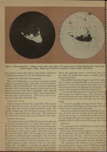
Figure 4. PPI presentation. Compare aerial radar scope photo with actual chart of island (Nantucket). Land, ships,<br />
aircraft appear white. Bright spot in center is position of plane which took picture.<br />
is in contrast to most other types of range finders which have<br />
a constant percentage error in determining the range.<br />
Azimuth and Elevation Determination<br />
The use of timed pulses, as we have seen, gives a simple<br />
means of measuring range. How then is the direction in<br />
which a target lies determined? This is done by providing<br />
the radar with a directional antenna, which sends out the<br />
pulses in a narrow beam, like a searchlight. Since azimuth<br />
and elevation determination are similar, only azimuth determination<br />
will be discussed here. There ar~ in use two systems,<br />
the single lobe and double lobe.<br />
Single Lobe System<br />
Here all energy is directed in a single lobe. The antenna<br />
may be rotated as the pulses are sent out, and we get back<br />
a "pip" when the antenna is pointed toward its target. \Ve<br />
get the strongest pip when the beam of energy sent out by<br />
the radar is pointed directly at the target. The azimuth of<br />
the center of the antenna gives us the azimuth of the target.<br />
Double Lobe System<br />
The method used in the SCR-268 and several other sets<br />
for azimuth determination is a double lobe system. Two<br />
identical lobes whose axes are displaced by som~ fixed angular<br />
distance are used. The two lobes intersect at onl" one<br />
point, known as the crossover point. Each lobe receives a<br />
pip from the target. \ Vhen the t\\'O pips are of equal size<br />
the antenna is pointed directly at the target. The use of two<br />
lobes instead of a single lobe greatly increases the precision<br />
of azimuth measurement because the operator has a more<br />
sensiti"e indicator to show whether or not he is off target.<br />
(Figure III.) In addition, it provides the operator with a<br />
sense of direction. If the antenna is off target the inequality<br />
of the pips shows him the direction to turn. These advan-<br />
Hence the single lobe system is most often used in s I<br />
sets while the double lobe system is usually employ<br />
fire control systems.<br />
The problem of antenna design is one of the major<br />
lems in radar, incomprehensible as this may seem t<br />
operator of a home radio receiver who finds a few yar<br />
wire strung up on his roof adequate for his purpose. A<br />
antenna must possess the following characteristics:<br />
a. It must be directional; that is, it must concentrat<br />
radio energy into a definite beam. All of the power sl<br />
go into this beam and none should leak off into "side 1<br />
in other directions, for such side lobes may be fatall"<br />
fusing .. ,<br />
b. It must be capable of being directed from a re<br />
place and must be stabilized on board ships and airpl<br />
to take out the motion of the craft itself.<br />
Antennas are made directional by building them up<br />
array of small antennas suitably spaced and timed to<br />
centrate the energy in one direction, or they may be<br />
on a searchlight principle of spraying the energy into a 1<br />
parabolic reflector which focuses the energy into a bea<br />
Illdicators<br />
Two principal classes of indica tors are used in radar<br />
meters and cathode-ray tubes.<br />
,\ Ieters have been ~sed principally for azimuth and<br />
vation indication: the needle deflecting to one side \<br />
the antenna was off target. However, meters present<br />
principal disadvantages (I) their slowness of reaction<br />
(2) their inability to distinguish between multiple tar<br />
The cathode-ra" tube indicators mav be subdivided<br />
two general classes. In one, termed "d~f1ection modula<br />
the echo shows as a deflection in a bri~ht line. The<br />
type of presentation was illustrated in Figure II. Ther