Design and Voltage Supply of High-Speed Induction - Aaltodoc
Design and Voltage Supply of High-Speed Induction - Aaltodoc
Design and Voltage Supply of High-Speed Induction - Aaltodoc
You also want an ePaper? Increase the reach of your titles
YUMPU automatically turns print PDFs into web optimized ePapers that Google loves.
110<br />
<strong>of</strong> this is the use <strong>of</strong> linear <strong>and</strong> cubic spline functions as a replacement for a FEM model as<br />
illustrated in Bianchi <strong>and</strong> Bolognani (1999). One potential use for the solution data would be the<br />
teaching <strong>of</strong> a neural network system.<br />
This combined use <strong>of</strong> discretization <strong>and</strong> solution history is applicable to any algorithm but it is most<br />
efficient when used with stochastic optimization algorithms like GA, fuzzy logic (Bianchi <strong>and</strong><br />
Bolognani, 1996) or simulated annealing. There, the reduction <strong>of</strong> calculation time is likely to be<br />
most significant. The use <strong>of</strong> solution history in surface fitting is also utilized best with stochastic<br />
algorithms, since the fitting requires large amounts <strong>of</strong> data in order to give a good estimation <strong>of</strong> the<br />
real behavior <strong>of</strong> the objective function.<br />
9.2 Optimization <strong>of</strong> a squirrel cage rotor <strong>of</strong> the 60 kW 60000 1 /min motor<br />
A numerical optimization <strong>of</strong> the rotor design was performed for a squirrel cage solid steel rotor. The<br />
16 bar <strong>and</strong> the 26 bar rotors compared in Chapter 5 were already designed <strong>and</strong> manufactured but the<br />
existence <strong>of</strong> better designs was checked. For the squirrel cage rotors seen in Fig. 9.3, the main<br />
variables are the number <strong>of</strong> cage bars <strong>and</strong> the width <strong>and</strong> height <strong>of</strong> a bar. The air gap was also taken<br />
as a free variable. The dimensions <strong>of</strong> stator <strong>and</strong> stator winding were kept constant. The objective<br />
was to minimize the temperature rise in the stator winding as this was considered the limiting factor<br />
for the utilization <strong>of</strong> the motor. The objective function for the temperature rise ∆T was <strong>of</strong> the<br />
following form:<br />
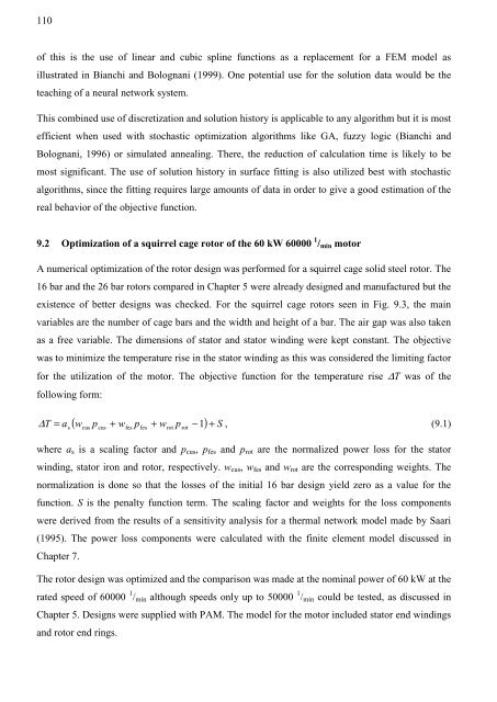
( w p + w p + w p − ) S<br />
∆ T = a<br />
1 + , (9.1)<br />
s<br />
cus<br />
cus<br />
fes<br />
fes<br />
rot<br />
rot<br />
where as is a scaling factor <strong>and</strong> pcus, pfes <strong>and</strong> prot are the normalized power loss for the stator<br />
winding, stator iron <strong>and</strong> rotor, respectively. wcus, wfes <strong>and</strong> wrot are the corresponding weights. The<br />
normalization is done so that the losses <strong>of</strong> the initial 16 bar design yield zero as a value for the<br />
function. S is the penalty function term. The scaling factor <strong>and</strong> weights for the loss components<br />
were derived from the results <strong>of</strong> a sensitivity analysis for a thermal network model made by Saari<br />
(1995). The power loss components were calculated with the finite element model discussed in<br />
Chapter 7.<br />
The rotor design was optimized <strong>and</strong> the comparison was made at the nominal power <strong>of</strong> 60 kW at the<br />
rated speed <strong>of</strong> 60000 1 /min although speeds only up to 50000 1 /min could be tested, as discussed in<br />
Chapter 5. <strong>Design</strong>s were supplied with PAM. The model for the motor included stator end windings<br />
<strong>and</strong> rotor end rings.


