Design and Voltage Supply of High-Speed Induction - Aaltodoc
Design and Voltage Supply of High-Speed Induction - Aaltodoc
Design and Voltage Supply of High-Speed Induction - Aaltodoc
You also want an ePaper? Increase the reach of your titles
YUMPU automatically turns print PDFs into web optimized ePapers that Google loves.
22<br />
<strong>and</strong> a low power factor. However, a common opinion seems to be that the increased need <strong>of</strong><br />
magnetization is more than compensated for by the reduction in rotor loss.<br />
Andresen et al. (1986) made a test for a 7 kW 50 Hz induction motor. The initial air gap, 0.35 mm,<br />
was selected according to rules commonly used. During the measurements, the authors reduced the<br />
diameter <strong>of</strong> the rotor by grinding in two steps. The resulting air gap was increased to 0.5 mm <strong>and</strong><br />
finally up to 0.67 mm. Sinusoidal voltage supply was used to run the motor at 50, 100 <strong>and</strong> 150 Hz.<br />
The results at a nominal torque showed that larger air gaps yielded much less power loss for the<br />
motor as the frequency was increased. Total loss at 150 Hz dropped by a third, when the air gap was<br />
increased from 0.35 mm to 0.67 mm. At 50 Hz <strong>and</strong> especially at no-load, the differences were<br />
small. This was due to increased winding loss compensating the decreased additional iron loss.<br />
The results apply in similar fashion also for the inverter fed induction machines operating at even<br />
higher frequencies. Thus, the selection <strong>of</strong> an air gap is mainly based on balancing the loss<br />
components so that the sum <strong>of</strong> the losses is minimized (Patent US 5473211). Also, the air gap<br />
affects the cooling if the cooling flow is forced through the air gap. This is the case in the motors<br />
considered. The loss balance is discussed in the next section.<br />
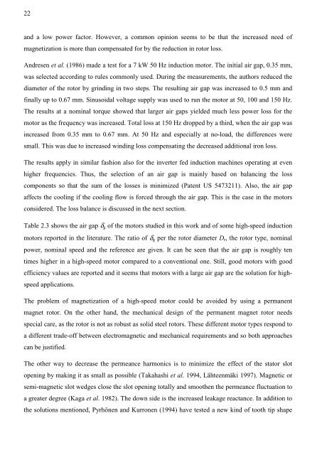
Table 2.3 shows the air gap δg <strong>of</strong> the motors studied in this work <strong>and</strong> <strong>of</strong> some high-speed induction<br />
motors reported in the literature. The ratio <strong>of</strong> δg per the rotor diameter Dr, the rotor type, nominal<br />
power, nominal speed <strong>and</strong> the reference are given. It can be seen that the air gap is roughly ten<br />
times higher in a high-speed motor compared to a conventional one. Still, good motors with good<br />
efficiency values are reported <strong>and</strong> it seems that motors with a large air gap are the solution for high-<br />
speed applications.<br />
The problem <strong>of</strong> magnetization <strong>of</strong> a high-speed motor could be avoided by using a permanent<br />
magnet rotor. On the other h<strong>and</strong>, the mechanical design <strong>of</strong> the permanent magnet rotor needs<br />
special care, as the rotor is not as robust as solid steel rotors. These different motor types respond to<br />
a different trade-<strong>of</strong>f between electromagnetic <strong>and</strong> mechanical requirements <strong>and</strong> so both approaches<br />
can be justified.<br />
The other way to decrease the permeance harmonics is to minimize the effect <strong>of</strong> the stator slot<br />
opening by making it as small as possible (Takahashi et al. 1994, Lähteenmäki 1997). Magnetic or<br />
semi-magnetic slot wedges close the slot opening totally <strong>and</strong> smoothen the permeance fluctuation to<br />
a greater degree (Kaga et al. 1982). The down side is the increased leakage reactance. In addition to<br />
the solutions mentioned, Pyrhönen <strong>and</strong> Kurronen (1994) have tested a new kind <strong>of</strong> tooth tip shape


