

Design and Voltage Supply of High-Speed Induction - Aaltodoc
Design and Voltage Supply of High-Speed Induction - Aaltodoc
Design and Voltage Supply of High-Speed Induction - Aaltodoc

You also want an ePaper? Increase the reach of your titles
YUMPU automatically turns print PDFs into web optimized ePapers that Google loves.
The copper coated solid steel rotor is similar to the rotor used for the 65 kW compressor drive<br />
presented in the previous chapter. The circumferential speed at 60000 1 /min is 280 m /s. As mentioned<br />
in Section 3.5, a maximum speed <strong>of</strong> 50000 1 /min was specified for the squirrel cage rotors. Thus, the<br />
comparison was made at 50100 1 /min, the circumferential speed being 235 m /s. Even at this speed, the<br />
use <strong>of</strong> a laminated squirrel cage rotor is not possible. Reasons for this were discussed in Chapter 3.<br />
5.1 Measurement setup<br />
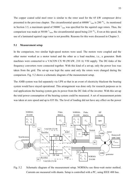
In the comparison, two similar high-speed motors were used. The motors were coupled <strong>and</strong> the<br />
other motor worked as a motor tested <strong>and</strong> the other as a load machine, i.e., a generator. Both<br />
machines were connected to a VACON CX 90 (90 kW, 210 A) VSI supply. The DC-links <strong>of</strong> the<br />
frequency converters were connected together. With this kind <strong>of</strong> a set-up, only the power loss was<br />
taken from the grid. The set-up was kept the same <strong>and</strong> only the rotors were changed during the<br />
comparison. Fig. 5.2 shows a schematic diagram <strong>of</strong> the measurement setup.<br />
The AMB system was fed separately via UPS so that in an event <strong>of</strong> electricity blackout the bearing<br />
system would have stayed operational. This arrangement was done only for research purposes as in<br />
real applications the bearing system gets its power from the DC-link <strong>of</strong> the inverter. With this set-up<br />
the total power consumption <strong>of</strong> the bearing system could be measured. A set <strong>of</strong> measurement points<br />
was taken at zero speed <strong>and</strong> up to 835 Hz. The level <strong>of</strong> loading did not have any effect on the power<br />
Synchronous<br />
generator<br />
NORMA<br />
D 6100<br />
Uin Iin Pin fin PC<br />
50 Hz<br />
PC<br />
VACON CX 90<br />
Rectifier<br />
DC link<br />
PC<br />
=<br />
=<br />
Rectifier<br />
DC link<br />
VACON CX 90<br />
Fluke<br />
8842A<br />
U d<br />
PC<br />
IGBT<br />
=<br />
PC<br />
NORMA<br />
D 6100<br />
Uin Iin Pin fin Battery<br />
=<br />
Fluke<br />
8842A<br />
U in<br />
Switch<br />
HP<br />
5316B<br />
rpm<br />
AMB<br />
motor<br />
PC = AMB<br />
generator<br />
Uin Iin NORMA<br />
IGBT<br />
Pin fin D 6100<br />
PC<br />
PC<br />
PC<br />
53<br />
Honeywell<br />
DPR 3000<br />
Tambient Tthermocouples Fig. 5.2 Schematic diagram <strong>of</strong> the measurement setup. NORMAs use three-watt meter method.<br />
Currents are measured with shunts. Setup is controlled with a PC, using IEEE 488 bus.


