

Design and Voltage Supply of High-Speed Induction - Aaltodoc
Design and Voltage Supply of High-Speed Induction - Aaltodoc
Design and Voltage Supply of High-Speed Induction - Aaltodoc

Create successful ePaper yourself
Turn your PDF publications into a flip-book with our unique Google optimized e-Paper software.
38<br />
presented in Section 3.2. The idea (Patent FI 100749) <strong>and</strong> the actual design <strong>of</strong> the rotor are not part<br />
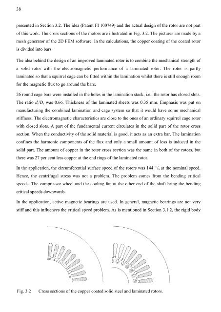
<strong>of</strong> this work. The cross sections <strong>of</strong> the motors are illustrated in Fig. 3.2. The pictures are made by a<br />
mesh generator <strong>of</strong> the 2D FEM s<strong>of</strong>tware. In the calculations, the copper coating <strong>of</strong> the coated rotor<br />
is divided into bars.<br />
The idea behind the design <strong>of</strong> an improved laminated rotor is to combine the mechanical strength <strong>of</strong><br />
a solid rotor with the electromagnetic performance <strong>of</strong> a laminated rotor. The rotor is partly<br />
laminated so that a squirrel cage can be fitted within the lamination whilst there is still enough room<br />
for the magnetic flux to go around the bars.<br />
26 round cage bars were installed in the holes in the lamination stack, i.e., the rotor has closed slots.<br />
The ratio dr/Dr was 0.66. Thickness <strong>of</strong> the laminated sheets was 0.35 mm. Emphasis was put on<br />
manufacturing the combined lamination <strong>and</strong> cage system so that it would have some mechanical<br />
stiffness. The electromagnetic characteristics are close to the ones <strong>of</strong> an ordinary squirrel cage rotor<br />
with closed slots. A part <strong>of</strong> the fundamental current circulates in the solid part <strong>of</strong> the rotor cross<br />
section. When the conductivity <strong>of</strong> the solid material is good, it acts as an extra bar. The lamination<br />
confines the harmonic components <strong>of</strong> the flux <strong>and</strong> only a small amount <strong>of</strong> loss is induced in the<br />
solid part. The amount <strong>of</strong> copper in the rotor cross section was the same in both <strong>of</strong> the rotors, but<br />
there was 27 per cent less copper at the end rings <strong>of</strong> the laminated rotor.<br />
In the application, the circumferential surface speed <strong>of</strong> the rotors was 144 m /s at the nominal speed.<br />
Hence, the centrifugal stress was not a problem. The problem comes from the bending critical<br />
speeds. The compressor wheel <strong>and</strong> the cooling fan at the other end <strong>of</strong> the shaft bring the bending<br />
critical speeds downwards.<br />
In the application, active magnetic bearings are used. In general, magnetic bearings are not very<br />
stiff <strong>and</strong> this influences the critical speed problem. As is mentioned in Section 3.1.2, the rigid body<br />
Fig. 3.2 Cross sections <strong>of</strong> the copper coated solid steel <strong>and</strong> laminated rotors.


