

Design and Voltage Supply of High-Speed Induction - Aaltodoc
Design and Voltage Supply of High-Speed Induction - Aaltodoc
Design and Voltage Supply of High-Speed Induction - Aaltodoc

Create successful ePaper yourself
Turn your PDF publications into a flip-book with our unique Google optimized e-Paper software.
12<br />
higher switching frequencies without causing excessive switching loss. Different voltage<br />
modulation techniques can be used. The voltage waveforms can be selected or optimized to produce<br />
low loss, torque ripple, noise etc., depending on the application <strong>and</strong> dem<strong>and</strong>s.<br />
The use <strong>of</strong> power electronics together with integrated control <strong>and</strong> information networks makes it<br />
possible to use <strong>and</strong> supervise the drives efficiently <strong>and</strong> cost-effectively. Processes can be adjusted<br />
without unnecessary losses by simply changing the supply frequency <strong>of</strong> the electric motor.<br />
Feeding an electric motor from an inverter sets some new requirements for the design <strong>of</strong> a motor.<br />
An increase in a supply frequency further emphasizes these requirements. The supply waveforms <strong>of</strong><br />
the voltage <strong>and</strong> current are not sinusoidal <strong>and</strong> more losses are induced in the motor. Some loss<br />
components such as eddy current loss are strongly frequency dependent <strong>and</strong> its share <strong>of</strong> the total<br />
loss increases as frequency increases. The change in loss balance makes the optimal design <strong>of</strong> the<br />
high-speed motor different from the design <strong>of</strong> a 50/60 Hz conventional motor.<br />
In this work, high-speed motors with a supply frequency up to 1000 Hz are studied. Output power is<br />
in the range <strong>of</strong> 50 − 65 kW. For an electric motor with one pole pair, the increased frequency means<br />
a rotational speed up to 60000 1 /min. The torques produced by these motors are around 10 - 20 Nm.<br />
In the motors studied, active magnetic bearings are used for contactless suspension. The motors are<br />
fed by voltage source frequency converters.<br />
The high-speed induction motor drives considered in this work have all the rotating components<br />
attached to the same shaft. The compressor wheel is attached to the same shaft with the rotor. The<br />
cooling fan <strong>of</strong> the motor is attached to the other end <strong>of</strong> the shaft. The cooling fan blows or sucks the<br />
air through the inner parts <strong>of</strong> the motor, air gap <strong>and</strong> end winding regions.<br />
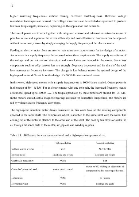
Table 1.1 Difference between a conventional <strong>and</strong> a high-speed compressor drive.<br />
<strong>High</strong>-speed drive Conventional drive<br />
<strong>Voltage</strong> source inverter YES NONE/YES<br />
Electric motor small size <strong>and</strong> weight large size <strong>and</strong> weight<br />
Gearbox & accessories NONE YES<br />
Control <strong>of</strong> power <strong>and</strong> work motor speed control<br />
motor on/<strong>of</strong>f, choking or adjustment <strong>of</strong><br />
compressor blades, motor speed control<br />
Lubrication NONE oil / grease<br />
Mechanical wear NONE bearings <strong>and</strong> gears


