Design and Voltage Supply of High-Speed Induction - Aaltodoc
Design and Voltage Supply of High-Speed Induction - Aaltodoc
Design and Voltage Supply of High-Speed Induction - Aaltodoc
You also want an ePaper? Increase the reach of your titles
YUMPU automatically turns print PDFs into web optimized ePapers that Google loves.
48<br />
4.2.2 Input current<br />
A lower input current indicates lower magnetization current <strong>and</strong> better efficiency at partial loads. A<br />
smaller frequency converter could be selected in some cases. Because the resistive loss in the stator<br />
winding is the main loss component to determine the temperature rise in the winding, the input<br />
current <strong>and</strong> the temperature rise are assumed to go h<strong>and</strong> in h<strong>and</strong>.<br />
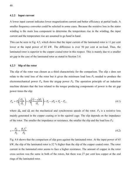
This can be seen in Fig. 4.5, which shows that the input current <strong>of</strong> the laminated rotor is 11 per cent<br />
lower at the input power <strong>of</strong> 65 kW. The difference is over 50 per cent at no-load. Thus, the<br />
laminated rotor is superior to the copper coated rotor in this respect. This is mainly due to a smaller<br />
air gap in the case <strong>of</strong> the laminated rotor as stated in Section 3.4.<br />
4.2.3 Slip <strong>of</strong> the rotor<br />
The slip <strong>of</strong> the rotor was chosen as a third characteristic for the comparison. The slip s does not<br />
relate to the total loss <strong>of</strong> the rotor but it gives the minimum load loss Ptl needed to produce the<br />
electromechanical power Pm from the airgap power Pδ. The operation principle <strong>of</strong> an induction<br />
machine dictates that the loss related to the torque producing components <strong>of</strong> power is the air gap<br />
power times the slip:<br />
( 1 s)<br />
P<br />
⎛<br />
⎜<br />
⎞<br />
⎟<br />
⎛<br />
⎜<br />
− ⎞<br />
⎟<br />
−<br />
⎝ ⎠ ⎝ ⎠<br />
m<br />
s<br />
m = Pδ<br />
⎜ ⎟ = Pδ<br />
⎜ ⎟ = Pδ<br />
− sPδ<br />
= Pδ<br />
Ptl<br />
, (4.1)<br />
s<br />
s<br />
where Ωm <strong>and</strong> Ωs are the mechanical <strong>and</strong> synchronous speeds <strong>of</strong> the rotor. Ptl is a resistive loss<br />
mainly generated in the copper coating or in the squirrel cage. The slip depends on the impedance<br />
<strong>of</strong> the rotor. The smaller the impedance or resistance, the smaller the slip <strong>and</strong> the load loss Ptl:<br />
P<br />
s =<br />
P<br />
tl<br />
2<br />
r<br />
(4.2)<br />
δ<br />
Rr<br />
I<br />
∝<br />
P<br />
δ<br />
Fig. 4.6 shows that the comparison <strong>of</strong> slip goes against the laminated rotor. At the input power <strong>of</strong> 65<br />
kW, the slip <strong>of</strong> the laminated rotor is 52 % higher than the slip <strong>of</strong> the copper coated rotor. The rotor<br />
current in the laminated rotor seems to face a higher resistance. The amount <strong>of</strong> copper in the rotor<br />
cross section was the same in both <strong>of</strong> the rotors, but there was 27 per cent less copper at the end<br />
rings <strong>of</strong> the laminated rotor.


