- Page 1 and 2: El 108 ACTA POLYTECHNICA SCANDINAVI
- Page 3 and 4: PREFACE This thesis is the result o
- Page 5 and 6: 5 Comparison of rotors for 60 kW 60
- Page 7 and 8: LIST OF SYMBOLS a Number of paralle
- Page 9 and 10: Rn Resistance of a parallel conduct
- Page 11 and 12: 1 INTRODUCTION The need for high ro
- Page 13 and 14: Conventional (high-speed) drive Hig
- Page 15 and 16: Chapter 5 reports the comparison of
- Page 17 and 18: Some penetration depth values are c
- Page 19 and 20: 2.2 Stator windings for high-speeds
- Page 21 and 22: ⎛ π ⎞ sin⎜ν ⎟ ⎛ π ⎞
- Page 23 and 24: Table 2.3 Air gap characteristics o
- Page 25 and 26: Cooling of the stator could need ax
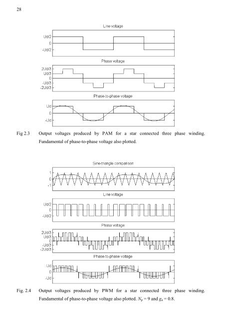
- Page 27: f sw N p = (2.9) fs The switching f
- Page 31 and 32: and eddy-currents traveling on the
- Page 33 and 34: support the squirrel cage winding,
- Page 35 and 36: 3.1.3 Rotor loss and friction loss
- Page 37 and 38: Table 3.1 High-speed induction moto
- Page 39 and 40: critical speeds are passed relative
- Page 41 and 42: Table 3.2 The free-free natural fre
- Page 43 and 44: Table 3.3 The free-free natural fre
- Page 45 and 46: 4 COMPARISON OF ROTORS FOR 65 KW 30
- Page 47 and 48: Temperature [ºC] 110 109 108 107 1
- Page 49 and 50: Temperature rise [K] 120 100 80 60
- Page 51 and 52: improve the laminated design, more
- Page 53 and 54: The copper coated solid steel rotor
- Page 55 and 56: As reported in Lähteenmäki et al.
- Page 57 and 58: Temperature rise [K] 100 80 60 40 2
- Page 59 and 60: Temperature rise [K] 140 120 100 80
- Page 61 and 62: 6. The rest of the loss is defined
- Page 63 and 64: Temperature rise [K] 100 80 60 40 2
- Page 65 and 66: 5.2.7 About the mechanical robustne
- Page 67 and 68: 6.1 Comparison of PAM and PWM for 6
- Page 69 and 70: h d = , (6.2) I I h, PAM where Ih,P
- Page 71 and 72: Fig. 6.4 Phase-to-phase voltage and
- Page 73 and 74: Temperature rise [K] 120 100 80 60
- Page 75 and 76: Machines loss [W] 12000 10000 8000
- Page 77 and 78: considerably higher than expected.
- Page 79 and 80:
In order to improve the performance
- Page 81 and 82:
l = + , (7.2) sλs 2leλ e l wλ w
- Page 83 and 84:
gap of 1 mm would yield an effectiv
- Page 85 and 86:
Table 7.1 Calculated effective leng
- Page 87 and 88:
Input current [A] 170 160 150 140 1
- Page 89 and 90:
8 CIRCULATORY CURRENTS IN A STATOR
- Page 91 and 92:
Table 8.1 Circulatory current loss
- Page 93 and 94:
Fig. 8.4 Strand currents in the two
- Page 95 and 96:
8.2 Impedance of the circulatory cu
- Page 97 and 98:
Because Φ l is approximately at th
- Page 99 and 100:
Table 8.2 Circulatory current loss
- Page 101 and 102:
Power loss [W] 3500 3000 2500 2000
- Page 103 and 104:
k cc 600 500 400 300 200 100 0 0 50
- Page 105 and 106:
9 OPTIMIZATION OF SOLID STEEL ROTOR
- Page 107 and 108:
whole solution space determined by
- Page 109 and 110:
the average time saving is 39 %. Th
- Page 111 and 112:
Fig. 9.3 Cross sections of the 16,
- Page 113 and 114:
Height of bar slot [mm] 8 6 4 2 0 R
- Page 115 and 116:
The different rotor topologies were
- Page 117 and 118:
possible. The coating practically v
- Page 119 and 120:
Table 9.3. Optimization results for
- Page 121 and 122:
Fig. 9.11 Initial (left) and opt. (
- Page 123 and 124:
high-speed induction machine. Accor
- Page 125 and 126:
Foelsch K. 1936. Magnetfeld und Ind
- Page 127 and 128:
Pyrhönen J. and Kurronen P. 1994.
- Page 129 and 130:
APPENDIX 129
- Page 131 and 132:
currents in the solid iron flow mor
- Page 133 and 134:
where the C sw E is the loss coeffi
- Page 135 and 136:
B. CALCULATION OF THERMAL CHARACTER
- Page 137 and 138:
Axial cooling duct Frame R fr3 Stat
- Page 139 and 140:
Linear equalities Ax = b, (C3) wher