

BBC Microcomputer Service Manual Oct 1985 Section 1 BBC Micro ...
BBC Microcomputer Service Manual Oct 1985 Section 1 BBC Micro ...
BBC Microcomputer Service Manual Oct 1985 Section 1 BBC Micro ...

Create successful ePaper yourself
Turn your PDF publications into a flip-book with our unique Google optimized e-Paper software.
The row address strobe signal is produced by a D-type flip-flop<br />
connected to the 8 and 4 MHz clock signals (half of IC44). This RAS<br />
signal then drives all of the dynamic RAMs via R106. The two banks of<br />
RAM are enabled by virtue of having their column address strobes<br />
individually available. in model A computers, with only one bank of<br />
RAM, CAS 1 is used. In the model B, CAS 0 controls the lower 16K and<br />
CAS 1 the upper 16K. The second bank of RAMs is selected by a 74LS51<br />
circuit (half of IC28) which controls the ,74S139 (half of IC45)<br />
producing the CAS signals. When A14 is high the B input is low thus<br />
selecting CAS 1. The other half of IC45 is used to select between the<br />
processor and CRT address lines.<br />
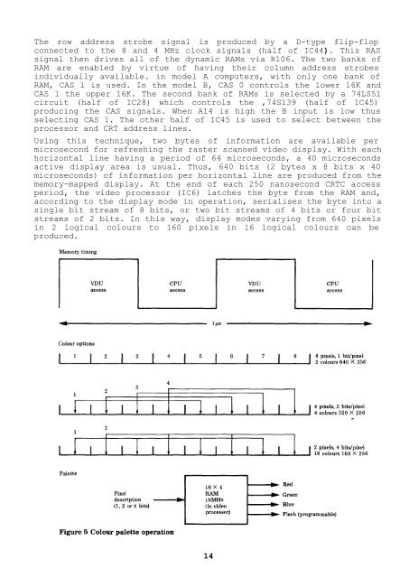
Using this technique, two bytes of information are available per<br />
microsecond for refreshing the raster scanned video display. With each<br />
horizontal line having a period of 64 microseconds, a 40 microseconds<br />
active display area is usual. Thus, 640 bits (2 bytes x 8 bits x 40<br />
microseconds) of information per horizontal line are produced from the<br />
memory-mapped display. At the end of each 250 nanosecond CRTC access<br />
period, the video processor (IC6) latches the byte from the RAM and,<br />
according to the display mode in operation, serialises the byte into a<br />
single bit stream of 8 bits, or two bit streams of 4 bits or four bit<br />
streams of 2 bits. In this way, display modes varying from 640 pixels<br />
in 2 logical colours to 160 pixels in 16 logical colours can be<br />
produced.<br />
14


