BBC Microcomputer Service Manual Oct 1985 Section 1 BBC Micro ...
BBC Microcomputer Service Manual Oct 1985 Section 1 BBC Micro ...
BBC Microcomputer Service Manual Oct 1985 Section 1 BBC Micro ...
You also want an ePaper? Increase the reach of your titles
YUMPU automatically turns print PDFs into web optimized ePapers that Google loves.
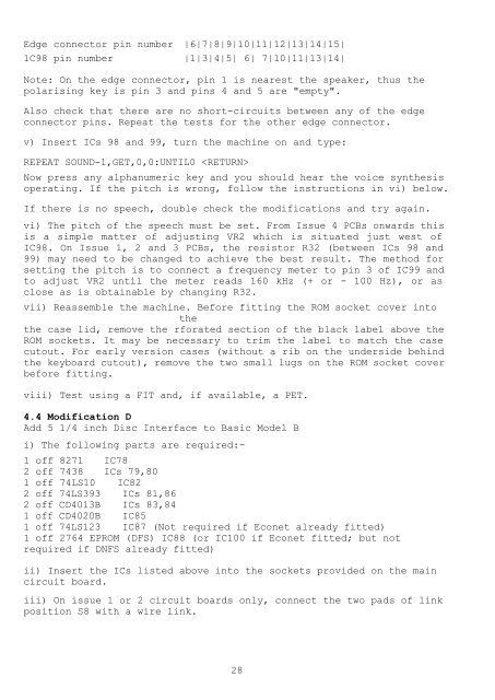
Edge connector pin number |6|7|8|9|10|11|12|13|14|15|<br />
1C98 pin number |1|3|4|5| 6| 7|10|11|13|14|<br />
Note: On the edge connector, pin 1 is nearest the speaker, thus the<br />
polarising key is pin 3 and pins 4 and 5 are "empty".<br />
Also check that there are no short-circuits between any of the edge<br />
connector pins. Repeat the tests for the other edge connector.<br />
v) Insert ICs 98 and 99, turn the machine on and type:<br />
REPEAT SOUND-1,GET,0,0:UNTIL0 <br />
Now press any alphanumeric key and you should hear the voice synthesis<br />
operating. If the pitch is wrong, follow the instructions in vi) below.<br />
If there is no speech, double check the modifications and try again.<br />
vi) The pitch of the speech must be set. From Issue 4 PCBs onwards this<br />
is a simple matter of adjusting VR2 which is situated just west of<br />
IC98. On Issue 1, 2 and 3 PCBs, the resistor R32 (between ICs 98 and<br />
99) may need to be changed to achieve the best result. The method for<br />
setting the pitch is to connect a frequency meter to pin 3 of IC99 and<br />
to adjust VR2 until the meter reads 160 kHz (+ or - 100 Hz), or as<br />
close as is obtainable by changing R32.<br />
vii) Reassemble the machine. Before fitting the ROM socket cover into<br />
the<br />
the case lid, remove the rforated section of the black label above the<br />
ROM sockets. It may be necessary to trim the label to match the case<br />
cutout. For early version cases (without a rib on the underside behind<br />
the keyboard cutout), remove the two small lugs on the ROM socket cover<br />
before fitting.<br />
viii) Test using a FIT and, if available, a PET.<br />
4.4 Modification D<br />
Add 5 1/4 inch Disc Interface to Basic Model B<br />
i) The following parts are required:-<br />
1 off 8271 IC78<br />
2 off 7438 ICs 79,80<br />
1 off 74LS10 IC82<br />
2 off 74LS393 ICs 81,86<br />
2 off CD4013B ICs 83,84<br />
1 off CD4020B IC85<br />
1 off 74LS123 IC87 (Not required if Econet already fitted)<br />
1 off 2764 EPROM (DFS) IC88 (or IC100 if Econet fitted; but not<br />
required if DNFS already fitted)<br />
ii) Insert the ICs listed above into the sockets provided on the main<br />
circuit board.<br />
iii) On issue 1 or 2 circuit boards only, connect the two pads of link<br />
position S8 with a wire link.<br />
28


