

BBC Microcomputer Service Manual Oct 1985 Section 1 BBC Micro ...
BBC Microcomputer Service Manual Oct 1985 Section 1 BBC Micro ...
BBC Microcomputer Service Manual Oct 1985 Section 1 BBC Micro ...

Create successful ePaper yourself
Turn your PDF publications into a flip-book with our unique Google optimized e-Paper software.
ii) Insert the above ICs into the sockets provided on the main<br />
circuit board. Solder the connectors on to the printed circuit board.<br />
iii) Cut the wire links at link positions S12 and S13. Move the MOLEX<br />
link at position S25 from South to North.<br />
iv) On issue 1, 2 or 3 circuit boards only, add a 2k2 ohm resistor<br />
between PL9 pin 1 and +5v on the solder side of the circuit board using<br />
a resistor with sleeved leads. +5v is available at IC85, pin 16 (33 mm<br />
due North of pin 1).<br />
v) On issue 1, 2 or 3 circuit boards only, cut the track connected to<br />
PL9 pin 23 (this may have previously been cut), then link IC69 pin 40<br />
to PL9 pin 19. This modification may have been made, and, if so, a<br />
check should be made to ensure that it has been correctly performed.<br />
vi) On issue 1 and 2 circuit boards only, PL9 pin 26 should be cut out<br />
of the header. Care should be taken to ensure that the pin is cut right<br />
back so that no connection can be made to it.<br />
vii) On issue 1 and 2 circuit boards only, a BC239 transistor should be<br />
added in place of link S1 as follows:- Cut the track between the centre<br />
and South pins of S1 on the solder side of the circuit board. Cut the<br />
two tracks connected to the North pin of S1 on the solder side of the<br />
circuit board, then reconnect the ends of these tracks leaving the<br />
North pin isolated. Insert a BC239 transistor into the S1 position with<br />
the base in the South pin, the emitter in the North pin, and the<br />
collector in the centre pin. Finally, link the North pin of S1 to IC27<br />
pin 7 with a short length of insulated wire.<br />
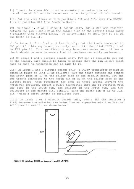
viii) On issue 1 or 2 circuit boards only, add a 4k7 ohm resistor (<br />
R162) between the existing two holes located approximately 5 mm East of<br />
IC70 pins 11 and 13, as shown below.<br />
26


