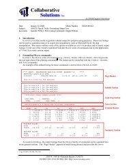
Hyper-Elastic Contact Analysis of a Push-Button ... - ANSYS Users
Hyper-Elastic Contact Analysis of a Push-Button ... - ANSYS Users
Hyper-Elastic Contact Analysis of a Push-Button ... - ANSYS Users

Create successful ePaper yourself
Turn your PDF publications into a flip-book with our unique Google optimized e-Paper software.
<strong>Hyper</strong>-<strong>Elastic</strong> <strong>Contact</strong> <strong>Analysis</strong> <strong>of</strong> a <strong>Push</strong>-<strong>Button</strong> Diaphragm<br />
Seal<br />
Jeffrey R. Annis<br />
Rockwell Automation- Allen Bradley<br />
Abstract<br />
World market pressures demand that corporations continually bring new and innovative products to market<br />
as rapidly as possible. Traditional build and test product development methods in today’s competitive<br />
markets are too slow, costly, and rarely yield optimized robust product designs. Complex large deflection<br />
patterns <strong>of</strong> rubber diaphragm seals combined with non-linear contact and material behaviors are difficult to<br />
calculate utilizing classical methods. Non-linear, <strong>Hyper</strong>-<strong>Elastic</strong> contact analysis capabilities found in finite<br />
element analysis programs like <strong>ANSYS</strong>, combined with fast workstations now allow engineers to rapidly<br />
evaluate and optimize rubber diaphragm seal designs prior to committing to costly prototypes and tooling.<br />
Presented is the non-linear finite element analysis <strong>of</strong> a rubber diaphragm seal utilizied in a pushbutton<br />
design. <strong>Analysis</strong> considerations encompassed, nonlinear hyper-elastic material behavior <strong>of</strong> the rubber, large<br />
deflection analysis <strong>of</strong> seal complex motion, and contact analysis with mating parts. Design parameters <strong>of</strong><br />
primary interest were, seal deflection patterns and seal actuation force as a function <strong>of</strong> travel.<br />
Technologies like finite element analysis play an important role in bringing robust new products <strong>of</strong> the<br />
highest quality to global customers. Product development and analysis teams working together are applying<br />
this technology to Seal designs at Rockwell Automation.<br />
Introduction<br />
Industrial controls devices such as, panel mounted sensors, indicator lights, or pushbuttons are required to<br />
meet many product standards such as IEC, NEMA and UL. These product standards define many test<br />
requirements which assure that products <strong>of</strong> this type, are designed correctly and can survive many<br />
industrial environmental conditions. Some examples <strong>of</strong> these are thermal cycling, mechanical shock,<br />
vibration, repetitive use, abuse by the user, and water or chemical splashes. In many applications, control<br />
panels with mounted indicator lights or pushbutton operator switches, house many sensitive electronic or<br />
electro-mechanical devices. These internal devices must be protected from the industrial environment,<br />
where chemical or water splashes can be an everyday occurrence.<br />
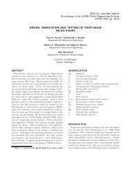
In applications like this, pushbutton operator switches must be capable <strong>of</strong> actuating through a required<br />
travel for contact make or break, have the right tactile feel for the operator, and yet provide an adequate<br />
seal from the outside environment. Water tight seal environments for pushbutton operators are defined by<br />
NEMA/UL or IEC water ingress test standards. Tests defined by these standards, evaluate the effectiveness<br />
<strong>of</strong> a seal design, by spraying an established rate <strong>of</strong> water, on a number <strong>of</strong> devices, at a specified distance,<br />
direction and time. This test is sometimes referred to as the hose test.<br />
A movable seal for a device such as a pushbutton, takes the form <strong>of</strong> a rubber membrane or corrugated<br />
diaphragm. The rubber diaphragm must provide an adequate water tight seal, accommodate the pushbutton<br />
operator travel, survive millions <strong>of</strong> operations, operate under varying temperature extremes, without<br />
impeding the motion <strong>of</strong> the pushbutton action or compromising the tactile feel for the user. Therefore<br />
developing a seal design, which meets all <strong>of</strong> the design requirements, utilizing build and bust development<br />
techniques can be very time consuming and costly. For this reason, computer aided design technologies in<br />
the form <strong>of</strong> <strong>ANSYS</strong> finite element analysis and fast workstations, now allow seal design engineers to<br />
evaluate and optimize design approaches prior to fabrication and testing <strong>of</strong> prototypes.
Molding rubber components like a diaphragm seal, in many cases require long processing times to allow<br />
for the curing process <strong>of</strong> rubber to occur. Because <strong>of</strong> this, it is not uncommon for a rubber mold die to have<br />
several hundred cavities based on part size and annual volume requirements. Consequently, getting the<br />
rubber part design right the first time is <strong>of</strong> major importance. Modifying a tool with several hundred<br />
cavities due to improper part design, is many times impractical and usually requires a new die or significant<br />
tooling costs to correct design errors. Major advantages <strong>of</strong> finite element modeling to develop rubber<br />
molded components, like a diaphragm seal, are to get the design right the first time, significantly reduce die<br />
rework costs and shorten time to market.<br />
Another application <strong>of</strong> finite element modeling is to study the influence <strong>of</strong> molding variations or part<br />
tolerances on part performance. This can be very useful to the design engineer in selecting tolerances and<br />
matching process capabilities with the part performance requirements. As an example, part finite element<br />
models <strong>of</strong> maximum material condition (MMC) versus least material condition (LMC) part size variations,<br />
can be evaluated and compared with product requirements. The focus <strong>of</strong> the following investigation,<br />
concentrates on the application <strong>of</strong> <strong>Hyper</strong>-<strong>Elastic</strong> contact analysis to optimize the design <strong>of</strong> a pushbutton<br />
diaphragm sealing system, utilizing the <strong>ANSYS</strong> finite element s<strong>of</strong>tware.<br />
Procedure<br />
<strong>Push</strong>button Operation and Diaphragm Seal Assembly<br />
Most pushbutton operators have an external button or lever that protrudes from the control panel which is<br />
activated manually by the user based upon demand. This external protruding button or lever is referred to<br />
as the pushbutton operator. Depending on the operator function, these pushbuttons maybe lighted or color<br />
designated to allow for easy functional identification by the user. Attached to the external button is a long<br />
cylindrical internal component called the plunger. As the button is depressed, the plunger transmits<br />
translational motion to protruding contact cartridge pins in the rear <strong>of</strong> the pushbutton operator device. This<br />
movement or depressing <strong>of</strong> contact cartridge pins causes a set <strong>of</strong> double break contacts to either make or<br />
break current. At rest, the contact blocks may either be in a normally open (NO) or normally closed (NC)<br />
state, depending on the type used. Multiple contact cartridges maybe snapped into the back <strong>of</strong> the<br />
pushbutton operator to control more than one circuit at a time. Electrical connections to the contact<br />
cartridges are made inside the panel or enclosure with screw clamp terminations.<br />
A preloaded return spring attached to the plunger assures that the button operator will always return to the<br />
original position when not depressed by the operator. The primary function <strong>of</strong> the diaphragm seal is to<br />
prevent water or chemicals from entering the pushbutton operator and into the inside <strong>of</strong> a front panel. The<br />
diaphragm must provide a reliable seal as well as allow ease <strong>of</strong> movement <strong>of</strong> the plunger over the entire<br />
range <strong>of</strong> travel. A photo <strong>of</strong> the pushbutton operator, diaphragm seal and push button cross-section are<br />
shown respectively in Figures 1-2.
Figure 1 - PHOTO OF PUSH BUTTON OPERATOR AND DIAPHRAGM SEAL
FIGURE 2 - CROSS-SECTION OF PUSH BUTTON OPERATOR<br />
<strong>Push</strong>button operator assembly starts first with mounting the diaphragm seal onto the plunger. The seal is<br />
stretched over the plunger using a special tool so that a sealing bead lies inside the external plunger groove.<br />
This procedure is similar to stretching a balloon over the nozzle <strong>of</strong> a helium bottle. Assembly <strong>of</strong> other<br />
internal components then proceed to complete the pushbutton product.<br />
<strong>Push</strong>button operators are mounted on a panel by securing the operator housing to the panel with a tightened<br />
nut and sealing panel gasket. The diaphragm provides a seal to the external environment at a second<br />
location between the housing and a tightened external bezel washer assembly. This pushbutton installation<br />
is then completed with snapping contact cartridges into the rear <strong>of</strong> the operator and wiring electrical<br />
terminations.<br />
Diaphragm Seal Design Considerations<br />
The primary function <strong>of</strong> the diaphragm is to provide a moving seal between the housing and movable<br />
plunger. A raised rubber bead on the diaphragm, fits into a groove on the bushing face, to form a water<br />
tight seal. Required clamp load to form this seal is provided by an externally tightened bezel. The
obustness <strong>of</strong> this seal is influenced by several factors such as groove depth, size <strong>of</strong> rubber bead, stiffness<br />
<strong>of</strong> rubber and clamp load. A second location <strong>of</strong> diaphragm sealing is found at the movable plunger. At this<br />
location, a rubber bead on the diaphragm, is stretched over the plunger containing a groove, analogous to<br />
stretching a balloon over a nozzle. Clamp load at this sealing location, is provided by the diametrical<br />
interference between the groove, bead and resulting hoop stress.<br />
In addition to providing adequate water tight seals at both locations, the diaphragm must move freely<br />
without buckling and utilize a minimum amount <strong>of</strong> force. Finite element analysis is a tool that can be very<br />
helpful in optimizing bead design, determining clamp loads, evaluating diametrical interference, sizing the<br />
diaphragm loop, and visualizing the seal motion or bead clamping action.<br />
<strong>Analysis</strong><br />
Finite Element Modeling Considerations and Model Creation<br />
A quarter symmetry solid model <strong>of</strong> the diaphragm was initially created by the product design engineer.<br />
This solid model created in Pro-Engineer was exported to <strong>ANSYS</strong> in the form <strong>of</strong> an IGES file. One<br />
advantage <strong>of</strong> letting the design engineer create the geometry is that he or she has control over the design,<br />
obtains a more in depth understanding <strong>of</strong> the product function and can share in some <strong>of</strong> the work <strong>of</strong> model<br />
creation. The seal model geometry was created so that the axis <strong>of</strong> revolution would lie along the global yaxis<br />
which is consistent for an axisymmetric finite element model. One <strong>of</strong> the symmetry cuts for the quarter<br />
model was made along the x-y plane. By creating the solid model in this manor, allowed for one surface <strong>of</strong><br />
the seal cross-section to be used for the axisymmetric finite element analysis directly. Based on experience<br />
<strong>of</strong> the author, a little up front communication with the design engineer in creating model geometry that is<br />
appropriate for FEA, can save a great deal <strong>of</strong> time for the finite element analyst. Another benefit is the<br />
product engineer gains an understanding <strong>of</strong> the benefits <strong>of</strong> FEA and is a part <strong>of</strong> the analysis and design<br />
optimization process.<br />
A routine was then written as part <strong>of</strong> the <strong>ANSYS</strong> input file, to import the Pro-E IGES file and clean up the<br />
geometry such that only a cross-section <strong>of</strong> the seal geometry lying in the x-y plane remained. Since the<br />
diaphragm seal geometry and deflection behavior is axisymmetric, an axisymmetric finite element<br />
representation <strong>of</strong> the seal was used for analysis purposes. The element selected to model the rubber<br />
diaphragm seal behavior was the hyper-elastic HYPER56 axisymmetric element.<br />
Rigid contact surfaces <strong>of</strong> the plunger I.D., plunger sealing groove, bushing sealing groove, and bushing<br />
clamping surfaces were modeled using TARGE169 rigid surface target elements. At potential regions <strong>of</strong><br />
contact between the rubber seal and rigid contact surfaces, CONTA171 elements were added. Bezel<br />
clamping <strong>of</strong> the seal bead between the washer and bushing was accomplished by simply imposing<br />
displacements on the seal opposite the bead. The magnitude <strong>of</strong> these imposed displacements was based the<br />
Bezel tightening rotation angle and thread pitch. Shown in Figure 3 is a plot <strong>of</strong> the diaphragm seal finite<br />
element model and contact surfaces <strong>of</strong> the plunger and bushing. Convergence <strong>of</strong> contact elements with<br />
rigid target surface elements was obtained by trial and error by adjusting the stiffness and convergence<br />
criteria for the contact elements.
FIGURE 3 - PUSH BUTTON DIAPHRAGM SEAL FINITE ELEMENT MODEL<br />
Since the rubber diaphragm undergoes significant distortion relative to the initial geometric shape, the<br />
stiffness changes as a function <strong>of</strong> deflection or seal distortion. Therefore this falls into the geometric nonlinearity<br />
class <strong>of</strong> problem referred as large deflection. The large deflection feature was turned on in the seal<br />
analysis models to capture this geometric non-linear phenomenon. In addition to the geometric nonlinearity<br />
<strong>of</strong> changing contact surfaces and large deflection stiffness behavior, the non-linear material<br />
characteristic <strong>of</strong> rubber was also considered.<br />
Characterization <strong>of</strong> Rubber with Moody-Rivilin Material Model<br />
Test data for various rubber molding compounds was provided by the molding manufacturer in the form <strong>of</strong><br />
stress-strain curves. The stress-strain data was curve-fitted to a simplified two term Moody-Rivilin material<br />
model to characterize to hyper-elastic behavior <strong>of</strong> rubber. This curve-fitting <strong>of</strong> data was accomplished<br />
utilizing the Moody-Rivilin curve fitting routine within the <strong>ANSYS</strong> prep7 portion <strong>of</strong> the program. Depicted<br />
in Figure 4 is a plot showing the excellent two term Moody-Rivilin material model fit to the original stressstrain<br />
curve data. Since rubber is an incompressible material with a poisson ratio equal to .5, to avoid<br />
numerical instabilities a value <strong>of</strong> .49 was utilizied in this analysis. To serve as an additional check on the<br />
material model fit <strong>of</strong> data, a simple axisymmetric test bar model was constructed and loaded through the<br />
same strain range as the vendor material data provided.
FIGURE 4 - MOONEY-RIVLIN RUBBER MATERIAL MODEL FIT<br />
An area <strong>of</strong> primary interest, was bending <strong>of</strong> the diaphragm seal loop as the push button plunger moves<br />
through the required range <strong>of</strong> motion. In the seal loop area region, the stress-strain levels fall almost in the<br />
linear range <strong>of</strong> the rubber stress-strain curve. Therefore having test data and a perfect fit in the highly nonlinear<br />
region <strong>of</strong> the rubber stress-strain curve was <strong>of</strong> less importance. The major emphasis for this<br />
investigation was correctly predicting the force required to move the seal through the required range <strong>of</strong><br />
motion. This force was mainly influenced by the seal loop bending stiffness and boundary conditions at the<br />
two sealing bead locations.<br />
Finite Element Model Loading Sequence<br />
The sequence <strong>of</strong> loading the seal progressed as a three step process. Step one was to mount the inner<br />
sealing bead on the plunger and inside the plunger groove. In practice this is done by stretching the seal<br />
bead with a special tool over the plunger and mounting surface. From a modeling standpoint this was done<br />
by starting the plunger surface target elements out at a small radius and moving them radially to a position<br />
equal to the plunger O.D. which picks up the appropriate sealing surfaces in the process. This action<br />
produces a hoop stress on the diaphragm sealing bead and is analogous to stretching a balloon over a<br />
nozzle. Step two <strong>of</strong> the loading sequence progresses with clamping the outer sealing bead between the<br />
bushing and bezel. This is accomplished in the product by tightening the bezel to some predetermined<br />
tightening torque. From a modeling standpoint this was conducted by deflecting nodes on the seal adjacent<br />
to the load washer an amount equal to the squeezing deflection typically found in the product. And lastly,
step three progressed with translational motion <strong>of</strong> the plunger resulting from a user pushing the external<br />
button. This loading action was modeled by translating the plunger target elements in the axial or vertical<br />
direction <strong>of</strong> the finite element model.<br />
Factorial Experimental Design Parameter Evaluation<br />
In the last 10 to 15 years there has been an upsurge <strong>of</strong> interest in fractional factorial experimental designs<br />
with the introduction <strong>of</strong> Taguchi Methods by Dr. Genichi Taguchi. A noted Japanese technical specialist,<br />
Dr. Taguchi promoted a renewed interest in the application <strong>of</strong> experimental design techniques for making<br />
product quality improvements [6]. He developed a simple method for constructing orthogonal experimental<br />
design arrays and linear graphs to evaluate factor interactions. Factorial or fractional factorial experimental<br />
design arrays are used to help identify significant manufacturing or design factors which have the most<br />
influence on variation <strong>of</strong> product performance. Factorial experimental designs are not a new technology,<br />
but were first introduced in the 1930’s by Frank Yates, as the famous Yates tables [7] to study and improve<br />
yields in the field <strong>of</strong> agriculture.<br />
An advantage with using the fractional factorial design approach is that the influence <strong>of</strong> many design<br />
factors can be examined without having to test for all the possible design factor combinations. Generally<br />
factorial design factors or main effects selected for evaluation are, set at two levels, high or low. The<br />
magnitude <strong>of</strong> these levels is somewhat arbitrary and may be based on manufacturing process or engineering<br />
defined tolerances. These factor levels are designated within the experimental design layout as numbers 1<br />
or 2. Traditionally factorial experimental design investigations are conducted by physically testing samples<br />
fabricated or manufactured to the factor levels by the experimental design array. Rather than physically<br />
testing prototypes, factorial experimental design investigations can be conducted by utilizing the computer<br />
simulation capability <strong>of</strong> the <strong>ANSYS</strong> finite element program. The peak actuation force <strong>of</strong> the pushbutton<br />
diaphragm seal, as influenced by several factors, was selected for such an investigation.<br />
Some examples <strong>of</strong> factors which can influence the seal actuation force are as follows: rubber molding<br />
compound, diaphragm loop wall thickness , length <strong>of</strong> seal loop, initial stretch or hoop stress in the seal I. D.<br />
and or bezel clamping pressure. To preserve the confidentiality <strong>of</strong> results, three <strong>of</strong> these factors were<br />
selected for factorial design investigation and will be referred to as factors A-C. Factor levels were<br />
established based on product usage, manufacturing tolerances, and product design. Each factor was set at<br />
two levels defined as 1-high and 2-low. The L8 factorial experimental design array consisting <strong>of</strong> 8<br />
combinations <strong>of</strong> main factors is shown in Figure 8. Since only three factors were selected, a full factorial<br />
experiment was constructed allowing all interactions between factors to be completely represented, without<br />
any errors introduced due to factor confounding.<br />
<strong>Analysis</strong> Results & Discussion<br />
As indicated previously, the seal finite element model loading sequence, progresses as a three step loading<br />
process. Shown in Figure 5 are finite element plots showing typical seal deflection patterns when stretched<br />
over the plunger and clamped by the bezel/washer assembly. A flat spot on both plunger sealing bead and<br />
bushing sealing beads can be noted as a result <strong>of</strong> the rubber stretching or clamping action. It can also be<br />
shown that the diaphragm seal I.D. surface has conformed to the rigid plunger contact surface.
FIGURE 5 - FEA PLOTS SHOWING DIAPHRAGM SEAL MOUNTED AND CLAMPED<br />
Once the diaphragm seal is mounted and clamped, the last loading consideration is a translational <strong>of</strong> the<br />
pushbutton plunger and diaphragm seal. This translation is depicted in Figure 6 with a sequence <strong>of</strong> four<br />
frames from start to finish. As the seal transitions through this travel, one can see from the FEA deflection<br />
plots how the loop rolls up the side <strong>of</strong> the plunger outer wall. A typical force versus deflection plot <strong>of</strong> this<br />
seal translational motion is shown in Figure 7. Very good correlation was obtained between finite element<br />
model predicted seal actuation force levels and Instron machine measured force levels.
FIGURE 6 - DEFLECTION SEQUENCE OF DIAPHRAGM SEAL OVER PUSH BUTTON<br />
MOVEMENT DURING OPERATION<br />
Normalizied Force<br />
Normalizied Seal Force vs Deflection<br />
Normalizied Deflection<br />
FIGURE 7 - NORMALIZIED SEAL FORCE VS DEFLECTION TRAVEL
The required seal actuation force, was selected for detailed study, utilizing an L8<br />
factorial experimental design. Since only 3 main effects were evaluated, a full factorial experimental design<br />
which considers all possible combinations, was selected for evaluation <strong>of</strong> factors A-C. Results <strong>of</strong> the 8<br />
different runs along with factor designated levels are shown in Figure 8. It can be seen that the highest<br />
actuation force level was obtained in run 4 with Factor A = 1, Factor B=2, and Factor C=2. From results <strong>of</strong><br />
an experimental design like this, factors having a major influence on a parameter like actuation force, can<br />
be easily identified. The factor having the most influence on actuation force was identified as Factor C and<br />
is shown in Figure 9, the main effects plot. <strong>Analysis</strong> <strong>of</strong> variance or ANOVA is a statistical technique that<br />
is used to determine which factors or interactions <strong>of</strong> main factors are statistically significant. As shown in<br />
the ANOVA table, Figure 10, only factors B and C are statistically significant and pass the F-statistical<br />
test. Factorial experimental design methods, as shown, can be useful in identifying the key design or<br />
process control factors influencing product performance and variation.<br />
L8 Factorial Experimental Design Layout<br />
Run Factor Factor Interaction Factor Interaction Interaction Interaction Normalizied<br />
Number A B AxB C AxC BxC AxBxC Force<br />
1 1 1 1 1 1 1 1<br />
2 1 1 1 2 2 2 2<br />
3 1 2 2 1 1 2 2<br />
4 1 2 2 2 2 1 1<br />
5 2 1 2 1 2 1 2<br />
6 2 1 2 2 1 2 1<br />
7 2 2 1 1 2 2 1<br />
8 2 2 1 2 1 1 2<br />
FIGURE 8 - FACTORIAL EXPERIMENTAL DESIGN LAYOUT<br />
Effects as a % <strong>of</strong> Max.<br />
Force<br />
30<br />
25<br />
20<br />
15<br />
10<br />
5<br />
0<br />
A<br />
Factor<br />
DOE Effects Plot<br />
B<br />
Factor<br />
c<br />
Factor<br />
FIGURE 9 - DESIGN OF EXPERIMENTS EFFECTS PLOT RELATED TO FACTOR<br />
INFLUENCE ON SEAL ACTUATION FORCE<br />
0.38<br />
0.85<br />
0.46<br />
1<br />
0.39<br />
0.77<br />
0.43<br />
0.95
Conclusion<br />
Seal Activation Force-<br />
ANOVA Table<br />
Source <strong>of</strong> Degrees <strong>of</strong> Sum <strong>of</strong> Sq. as % <strong>of</strong> Total F-statistic<br />
Variation Freedom % <strong>of</strong> Factor C Variation<br />
Factor B 1 5.3 5 22<br />
Factor C 1 100 93 402<br />
Interaction 1 1.3 1 5.3<br />
BxC<br />
Pooled 4 1 1<br />
Interactions<br />
F=7.71 at 95%<br />
confidence<br />
FIGURE 10 - SEAL ACTIVATION FORCE ANALYSIS OF VARIANCE TABLE<br />
<strong>Hyper</strong>-<strong>Elastic</strong> finite element analysis capabilities within the <strong>ANSYS</strong> program, allow engineers to rapidly<br />
evaluate and optimize complex non-linear material and contact behavior <strong>of</strong> rubber diaphragm seals prior to<br />
fabrication <strong>of</strong> costly proto-types and tooling. <strong>Hyper</strong>-<strong>Elastic</strong> seal analysis used in conjunction with factorial<br />
experimental design studies also help identify key design factors which contribute most significantly to<br />
product variation. Product development and analysis teams working together are applying this technology<br />
to bring robust seal designs and pushbutton products to Rockwell Automation customers.<br />
References<br />
1. Annis, J. R., “Application <strong>of</strong> 3-D Magnetostatic <strong>Analysis</strong> and Taguchi Methods to Sealed Switch<br />
Design”, <strong>ANSYS</strong> Magnetics Symposium, Swanson <strong>Analysis</strong> Systems, Inc., May 1994.<br />
2. Annis,J. R., “Electromagnetic <strong>Analysis</strong> to Optimize the Design <strong>of</strong> Hall Effect Current Sensors”,<br />
<strong>ANSYS</strong> Conference, <strong>ANSYS</strong>, INC., Aug. 2000<br />
3. Box, G.E., Hunter, W.G. , Hunter, S.J., “Statistics for Experimenters-An Introduction To Design, Data<br />
<strong>Analysis</strong>, and Model Building”, Wiley, 1978<br />
4. Miller, I. and Freund,J.E., “Probability and Statistics for Engineers”, Prentice-Hall,1965<br />
5. “Structural Non-linearities User’s Guide for Revision 5.0” ,<strong>ANSYS</strong> INC., 1993<br />
6. Taguchi, G., “Introduction to Quality Engineering-Designing Quality into<br />
Products and Process”, Kraus Int. Publ., 1987<br />
7. Yates, F., “The Design and <strong>Analysis</strong> <strong>of</strong> Factorial Experiments”, Imperial Bureau <strong>of</strong> Soil Science,<br />
Technical Communication No. 35, Harpenden,1937<br />
8. Yates, F., “The Principals <strong>of</strong> Orthogonality and Confounding in Replicated Experiments”, Journal <strong>of</strong><br />
Agricultural Science, 23,1933